

McDonnell & Miller WFE-24, WFE-120 Instruction Manual
INSTRUCTION MANUAL
211163
MM-323G
Power
Model V
oltage** Consumption*
WFE-24 24VAC 15VA
WFE-120 120VAC 20VA
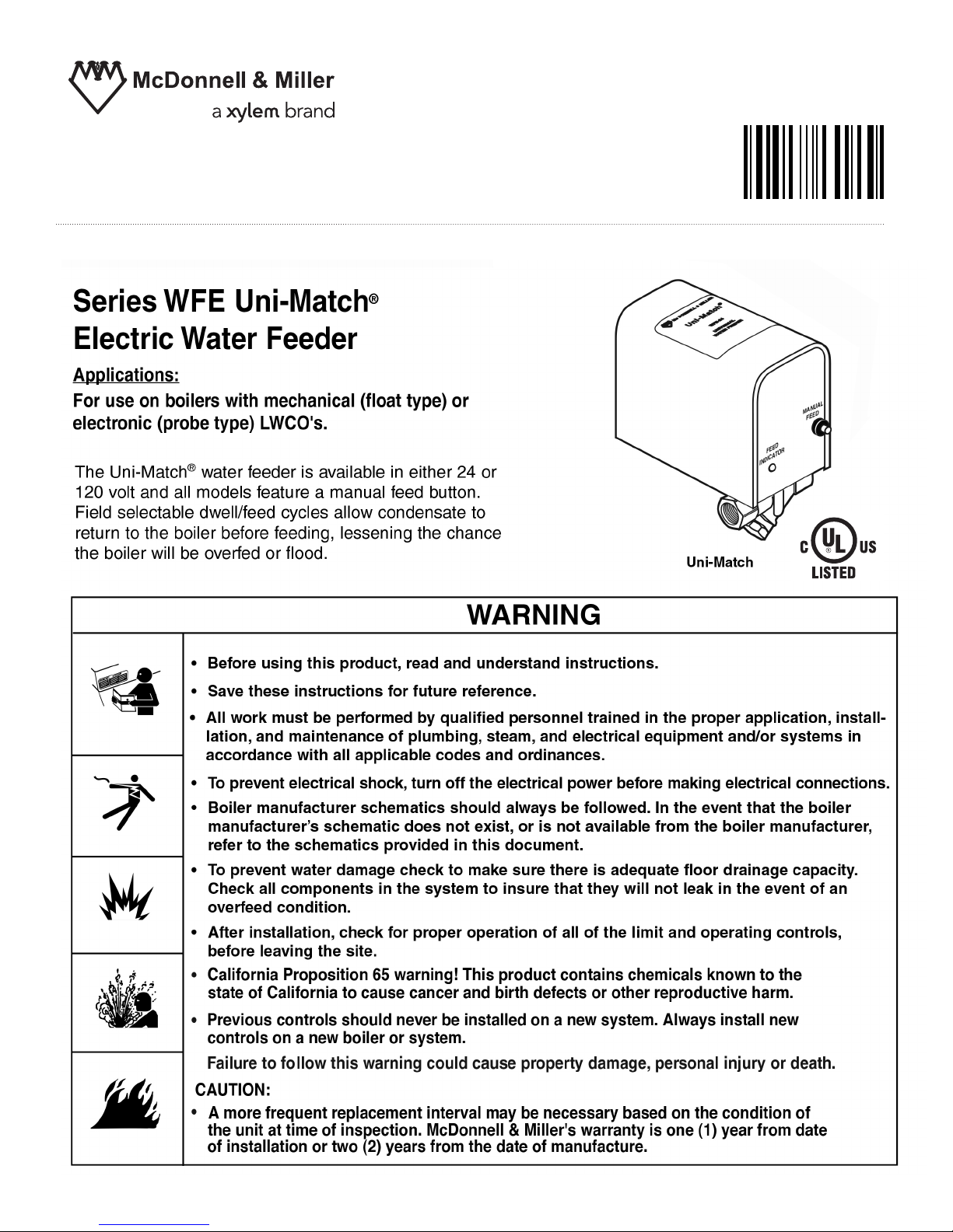
WA
TER FEEDER
INLET
VALV E
OUTLET
VALV E
UNION
UNION
STRAINER
CITY
WATER SUPPLY
CHECK
VALV E
BYPASS
VALV E
UNION
BYPASS
CONNECT TO
RETURN HEADER
ON BOILER
2
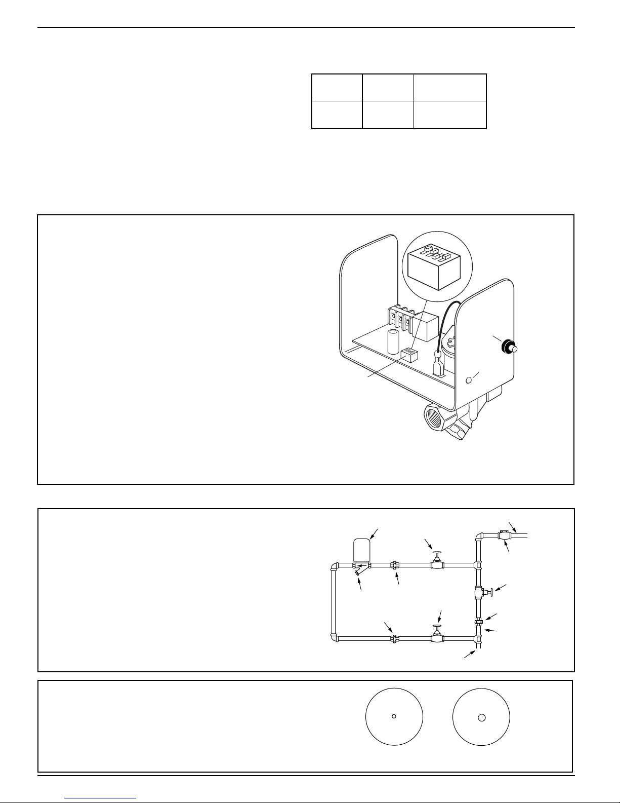
1a. Control must be installed within eyesight of boiler.
b. Clearance must be provided on all sides to
service control.
c. Unit must be installed in a horizontal pipe
in an upright position.
d. Arrow on feeder must point in the
direction of flow into the boiler.
e. Install isolation valves and unions on the
inlet and outlet piping for easier trouble
shooting and repair/replacement.
f. Install manual fill valve and bypass line for
removal while the boiler is in service.
2. Water f
eeders are shipped from the factory equipped
for a 2 gpm feed rate. A separate kit with instruction
sheet and field installable orifices for 1 gpm and 4 gpm
feed rates is included. If the alternate feed rates are
required, refer to the instruction sheet provided with the
kit for orifice replacement.
1 GPM
Orifice
4 GPM
Orifice
SPECIFICATIONS
Maximum W
ater Pressure:
150 psi (10.5 kg/cm
2
)
Maxim
um Boiler Pressure:
15 psi (1 kg/cm
2
)
Pipe Connections:
3/8" NPT (s
w
eat adapters included for connection
to 1/2" copper pipe)
Flow Data:
2 gpm (7.6 lpm) standard
Orifices included to change feed rate to 1 gpm
(3.8 lpm) or 4 gpm (15.1 lpm)
Maximum Water Temperature:
120 F (49 C)
Maximum Ambient Temperature:
100˚F (38˚C)
Dwell/Feed Selector Switch
The water feeder has a DIP
type switch block with
four on/off switches. Each switch has a specific
dwell/feed cycle which is activated upon receiving
a signal from the LWCO. The feeder will be deactivated when the LWCO is satisfied or if the
dwell/feed period has been exceeded.
Manual Feed
There is a man
ual f
eed button which when pressed
will add water to the boiler.
Multi-Color LED
A multi-color LED indicates status dur
ing operation,
incorrect switch selection and when dwell/feed
cycle has been exceeded.
Dwell/Feed Cycle Limit
The feeder will stop f
eeding water whenever the
selected dwell/feed cycle time has been exceeded
and the LWCO is still sending a signal.
STEP 1 - Installation
Electrical Ratings
* During Feed Cycle
** 50/60 Hz
o
o
eed
Dwell/F
Selector Switch
4
3
2
1
OFF
SW1
ON
Manual
Feed
Button
Multi
Function
LED
3
Boiler man
ufacturer schematics should be followed. In
the event that the boiler manufacturer's schematic does
not e
xist, or is not available from the boiler manufacturer,
ref
er to the schematics provided in this document.
IMPOR
TANT
To prevent electrical shock, turn off the
electrical po
wer before making electrical
connections.
F
ailure to follow this warning could cause
pr
operty damage, personal injury or death.
W
ARNING
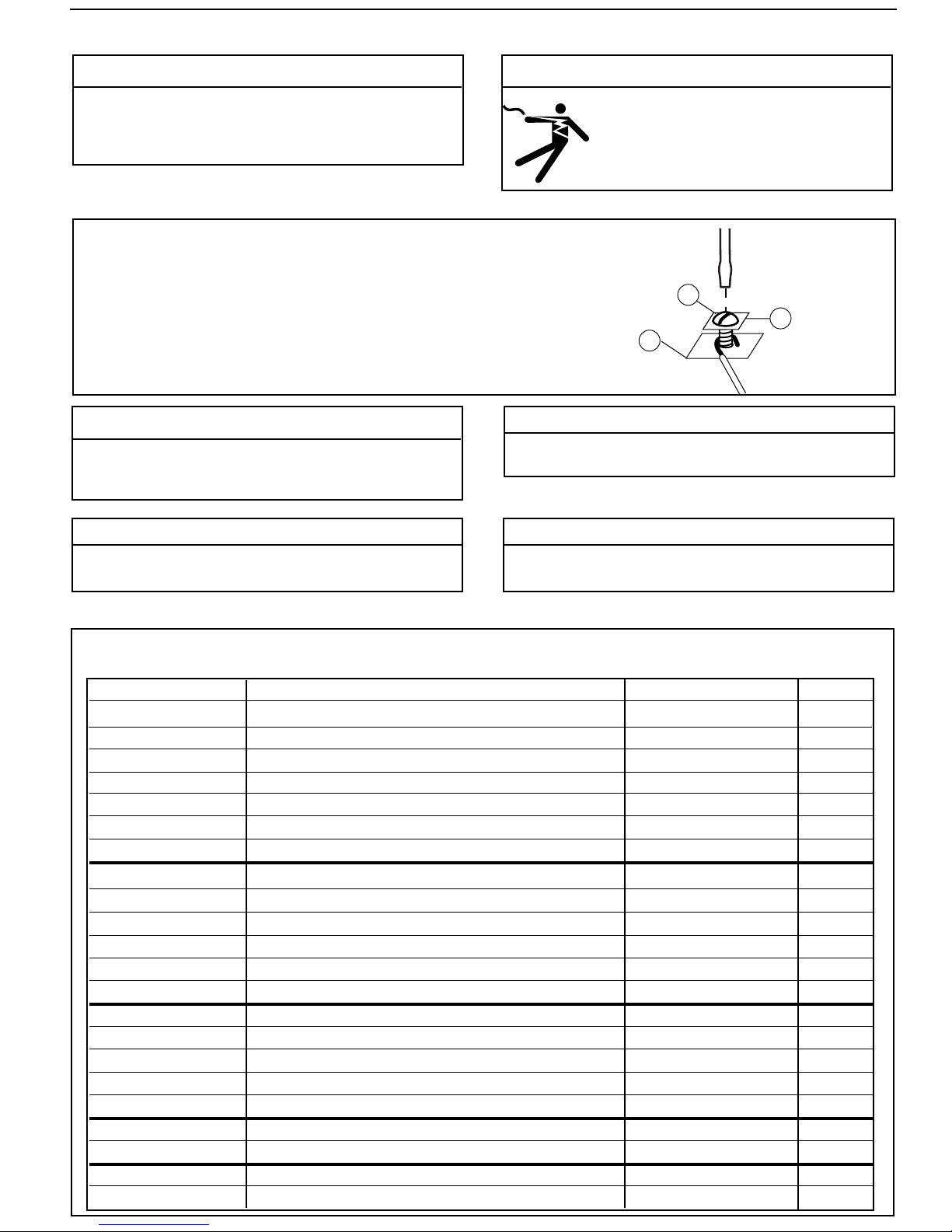
T
erminal Connections
N
P
M
F
or all wire connections to the terminal block (M).
1.
Strip about 1/3" (8.5 mm) of insulation from the wire.
2.
Loosen the terminal screw (N) but DO NOT
REMO
VE. Move the wire clamping plate (P) back
until the plate touches the bac
k side of the screw head.
3.
Insert the stripped end of the wire under the wire
clamping plate (P) and securely tighten the
ter
minal screw (N).
Do not use automatic water f
eeders with manual reset
L
WCO's. Failure to follow this warning could cause
flooding, property damage, personal injury or death.
W
ARNING
Unless otherwise noted,
water feeder voltage should be
the same as the L
WCO and burner circuit voltage.
NO
TE
Before wiring water feeder, operate boiler and check all
saf
ety devices.
NO
TE
Wire m
ust be 18 AWG (min) or as required by local code.
Wire insulation rating m
ust be at least 167˚F (75˚C)
NO
TE
STEP 2 - Electrical Installation
Feeder Model
LWCO Model Diagram Number Page
WFE-24
PS-802 with burner wiring harness 1 4
WFE-24 PS-802 with burner terminal connections 1 4
WFE-24
67 w/24 volt burner circuit 4 4
WFE-24
67 w/120 volt burner circuit 6 4
WFE-24
67G (millivolt burner circuit) 9 5
WFE-120
PS-801 with numbered terminals 2 4
WFE-120 PS-801 with lettered terminals 3 4
WFE-120
67 w/24 volt burner circuit 7 4
WFE-120
67 w/120 volt burner circuit 5 4
WFE-120
67G (millivolt burner circuit) 8 5
WFE-24
Hydrolevel 400 10 5
WFE-24
Hydrolevel CG400 11 5
WFE-120
Hydrolevel 450 12 5
WFE-120
Hydrolevel CG450 13 5
WFE-120
Hydrolevel CGT450 14 6
WFE-24
Honeywell LWCO (24 volt) 15 6
WFE-120
Honeywell LWCO (120 volt) 16 6
WFE-24
TACO LWCO (24 volt) 18 6
WFE-120
TACO LWCO (120 volt) 17 6
Wiring Diagram Selection Chart
Based on the w
ater feeder and low water cut-off combination you are installing, select proper wiring
diag
ram and proceed to that page.
WFE-24
PSE-802 with burner wiring harness
WFE-24
PSE-802 with burner terminal connections
WFE-120
PSE-801 with lettered terminals
1 4
1 4
3
4
 Loading...