

McDonnell & Miller MM 286 User Manual
Series 1575
Low Water Cut-Off/Pump Controller
For Steam Boilers and Other Level Control Applications
FEATURES
Probe Chamber:
• Cast Iron Body
• Sight Glass Tappings
• Gage Cock Tappings
• Stainless Steel Probes
• NEMA 4X Electrical Enclosure
• 250 psi Maximum Working Pressure
McDonnell & Miller
Installation & Maintenance
Instructions
MM-286
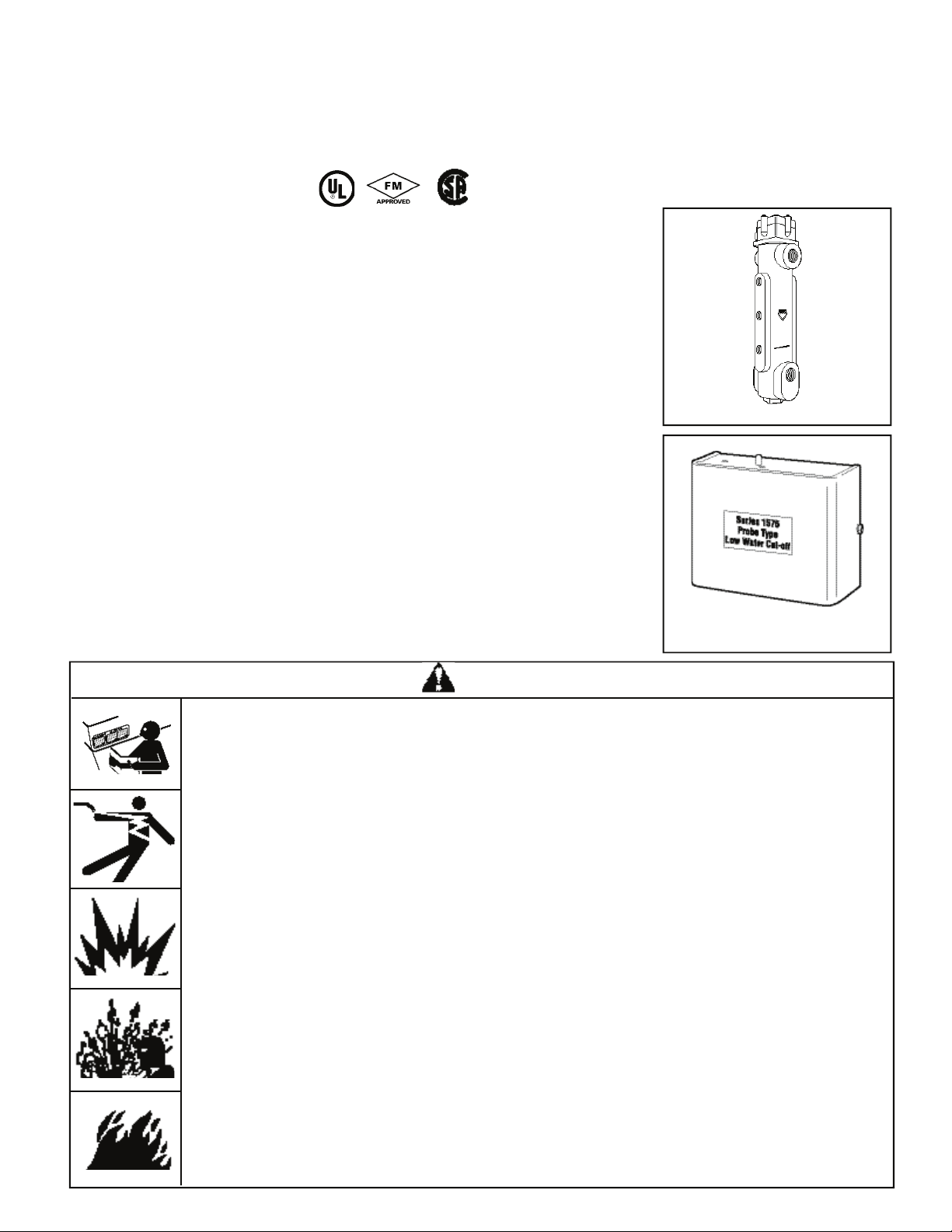
Probe Chamber
Electronic Control Unit
WARNING
• Before using this product read and understand instructions.
• Save these instructions for future reference.
• All work must be performed by qualified personnel trained in the proper application, instal-
lation, and maintenance of plumbing, steam, and electrical equipment and/or systems in
accordance with all applicable codes and ordinances.
• To prevent serious bu r n s , the boiler must be cooled to 80˚F (27˚C) and the pressure must be
0 psi (0 bar) before serv i c i n g .
• To prevent electrical shock , turn off the electrical power before making electrical connections.
• This low water cut-off must be installed in series with all other limit and operating
installed on the boiler. After installation, check for proper operation of all of the limit and
operating controls, before leaving the site.
• We recommend that secondary (redundant) low water cut-off controls be installed on all
steam boilers with heat input greater than 400,000 BTU/hour or operating above 15 psi of
steam pressure. At least two controls should be connected in series with the burner control
circuit to provide safety redundancy protection should the boiler experience a low-water
condition. Moreover, at each annual outage, the low water cut-offs should be dismantled,
inspected, cleaned, and c
• To prevent serious personal injury from steam bl ow dow n , connect a drain pipe to the contro l
opening to avoid exposure to steam discharge.
• To prevent a fire, do not use this low water cut-off to switch currents over 16A, 1 Hp at
120 VAC or 8A, 1 Hp at 240 VAC, unless a starter or relay is used in conjunction with it.
Failure to follow this warning could cause property damage, personal injury or
hecked for proper calibration and performance.
controls
death.

2
Electronic Control Unit
Burner Relay Time Delay
The field-adjustable time delay (DOB) helps to
p r e vent nuisance bu r ner shut-dow n . The number
of seconds water needs to be off the longest probe
b e f ore the bu r ner will shut down can be set
b e t w een 0 and 60 seconds.
Redundant Low Water Cut-Off
When the boiler water drops below the middle
p r o b e , a 3 minute timing circuit will be activa t e d . I f
water does not return to the middle probe within
three minu t e s, the bu rner relay will shut dow n . T h e
Red LED will flash once eve r y second if this
condition occurs.
• Automatic Reset units will automatically reset
when the water level is restored to the middle probe.
N O T E : The timing circuit will automatically reset
if the water level returns to the middle probe within
3 minu t e s.
Redundant Pump Off
The pump relay will be activated, turning the pump
on after water drops below the middle probe. If the
water level is not restored to the top probe within 3
m i nutes the pump relay will be deactivated, shutting
off the pump
. After the pump relay is deactiva t e d ,
n o r mal operation is resumed. Water must again
drop off the middle probe to activate the pump
r e l a y. There is no LED signal for this occura n c e.
A d j u s t a ble Pump Diffe r e n t i a l s
The water level positions for turning the pump on
and off and obtaining the needed pump diffe r e n t i a l s
are changed by cutting the length of the middle and
s h o r test probes.
3
SPECIFICATIONS
M a x i m um Pressure: 150 psi (10.5 kg/cm2)
Burner Delay (DOB): 0 to 60 seconds (Field Adjustabl e )
Ambient Te m p : 120˚F Max.
N O T E : The circuit board is protected with a sensor which will
shut down the unit if the temperature at the board ex c e e d s
176˚F (80˚C). The board will reset when the temperature at
the board drops below 167˚F (75˚C).
ELECTRICAL RATINGS & SWITCH RATINGS
Supply Probe Full Load (Amps) Locked Rotor (Amps) Pilot Duty (VA) Motor (HP)
Voltage Voltage NO (NC), VAC NO (NC), VAC NO (NC), VAC NO (NC), VAC
120 VAC 5 VAC 16 (5.8), 120 96 (34.8), 120 470 (290),120 1 (1/4), 120
50/60 HZ maximum 8 (2.9), 240 48 (17.4), 240 470 (290), 240 1 (1/4), 240
M a x i m um System Water Te m p e r a t u r e : 406˚F (208˚C)
M a x i m um System Water Pressure: 250 psi (17.6 kg/cm
2
)
M a x i m um System Steam Pressure: 250 psi (17.6 kg/cm
2
)
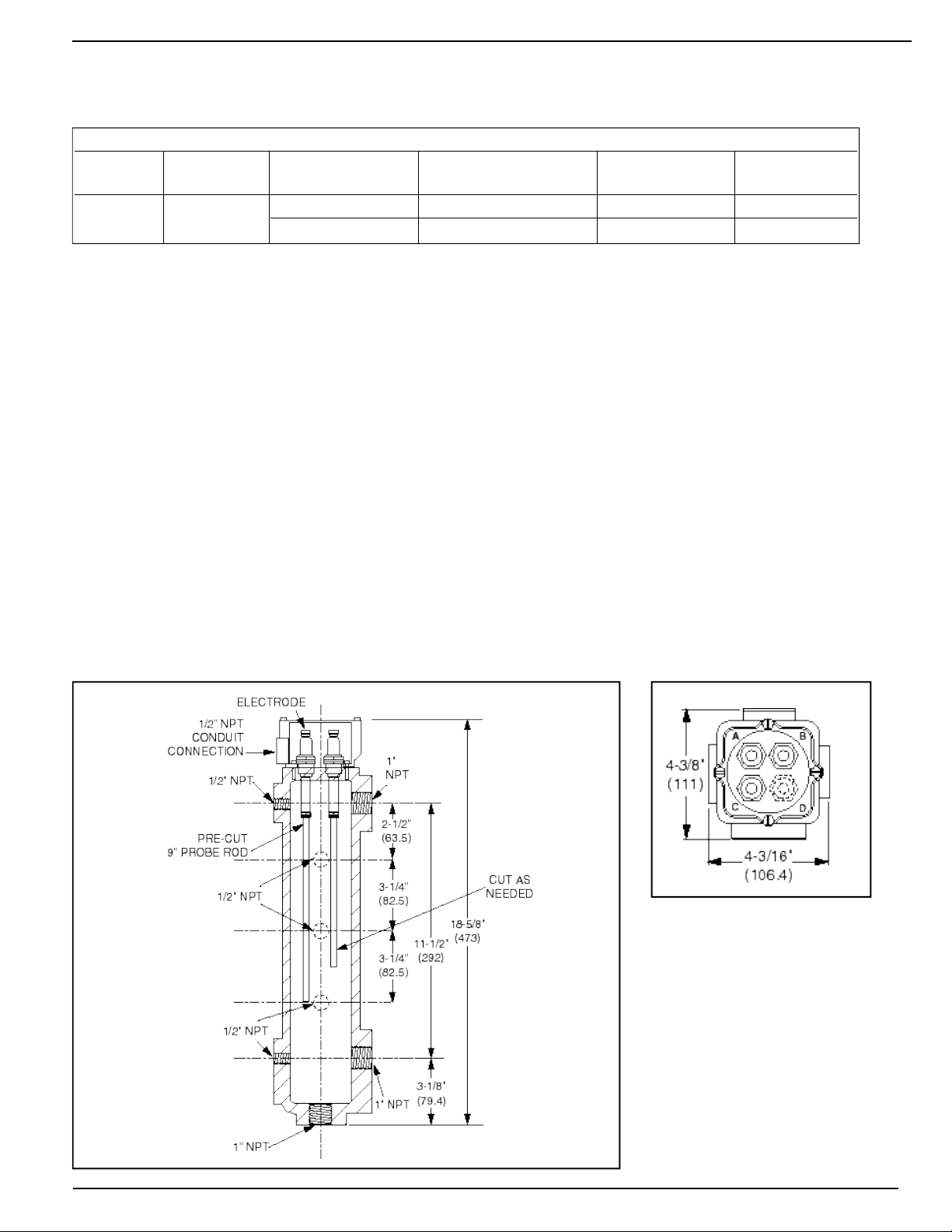
All probes in the Series 1575 units are sent from the factory pre-cut to
9" length (229mm). Any of the probes can be used as the low water
cut-off level probe. The 9" length positions the probe at the low water
cut-off cast-in line on the chamber body. The remaining probes can be
‘cut to length’ using a metal cutting saw to achieve desired pump control
(pump on/pump off) and pump differential levels. Approximately 1 inch
of the metal probe rod should be exposed below the Teflon® coating.
4
When the water level in the boiler drops below the
middle probe, the circuit is broken which will
a c t i v ate the pump relay, turning the pump on. W h e n
the water level rises above the shortest probe, the
circuit is made and the pump relay is deactiva t e d ,
t u r ning the pump off.
When the water level in the boiler drops below the
longest probe, the circuit is broken which will
d e a c t i v ate the bu rner relay, turning the bu rner off.
When the water level is restored to the middle
p r o b e , the bu r ner relay will be activated (bu rner on)
for auto reset controls only.
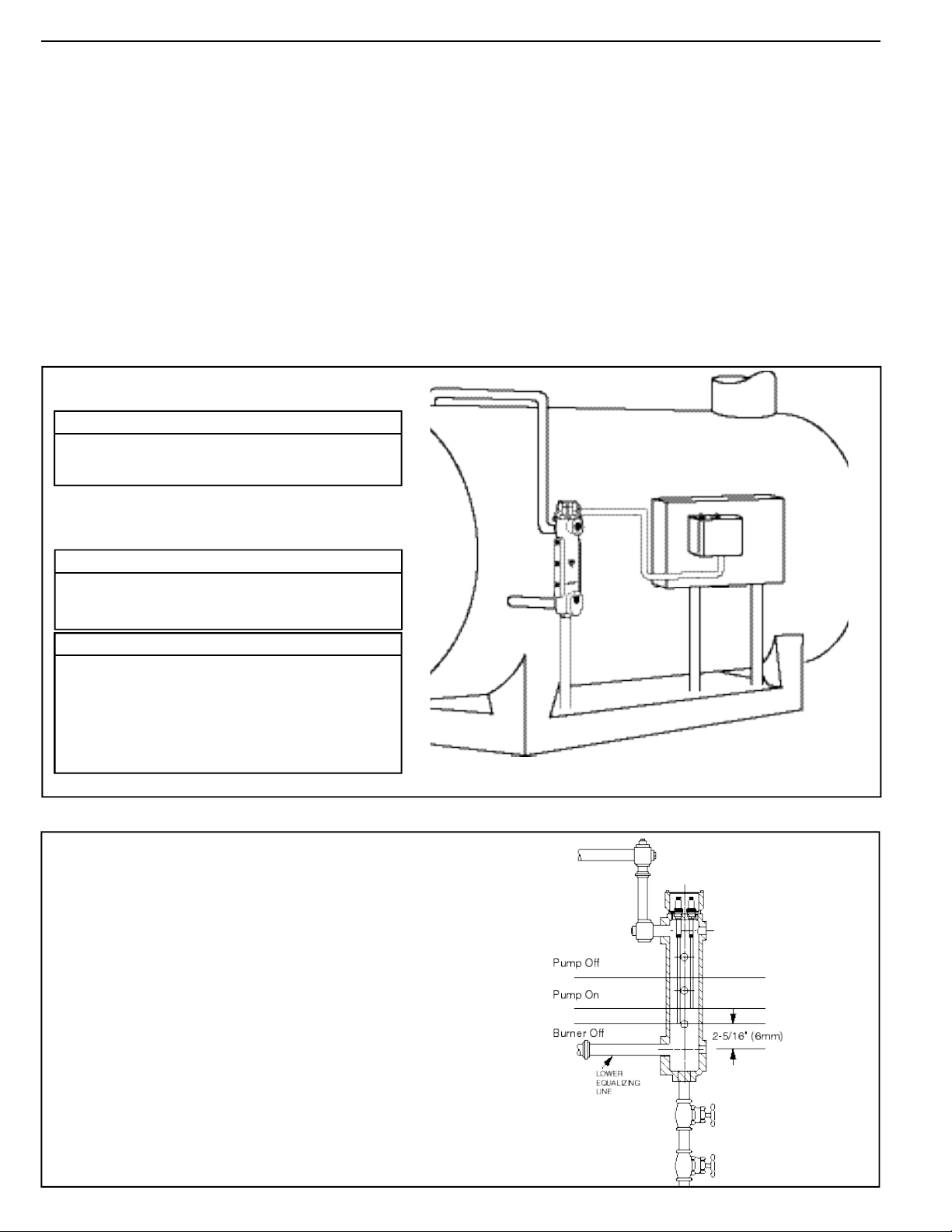
SWITCH SETTINGS:
Chamber
STEP 1 - Installation
TOOLS NEEDED:
One (1) pipe wrench, one (1) flathead screwdriver and/or 11/32" nut driver,
one (1) metal-cutting saw, one (1) 9/16" socket or wrench and pipe sealing compound.
If the control will be the primary low water fuel
cut-off, size the steam (top) and water (bottom)
equalizing pipe lengths to the chamber so that the
cut-off level mark is 1
1
/2" (38mm) below the
boiler’s normal water level, but not lower than
the lowest safe permissible water level, as
determined by the boiler manufacturer.
OR
If the control will be the secondary low water
fuel cut-off, s i z e the steam (top) and water (bottom)
equalizing pipe lengths to the chamber so that the
cut-off level mark is at or abov e the lowest safe
p e r m i s s i b l e water level, as determined by the
boiler manufacturer.
• Mount C o n t r ol Box in a suitable location near
the boiler’s main electrical panel.
• Install electrical conduit between electrical
enclosure of the P robe Chamber and
C o n t r ol Box .
• Pull four (4) wires through conduit.
Boiler sight glass must be visible from location of
Control Box and must be within 25 feet of Control
Box.
NOTE
R e fer to and fo l l ow local codes and standard s
when selecting conduit and electrical fittings.
Wires from Electrical Enclosure of the Pro b e
Chamber to Control Box must be in their own
c o n d u i t . If they are run in conduit with other wires,
there may be interference that can affect the
performance of the control.
NOTE
Wire must be 18 AWG stranded with glass braided
silicone jacket (UL 3071) suitable for high temperature (200˚C) service.
NOTE
SPECIFICATIONS (cont.)
 Loading...