

McDonnell & Miller FS-5 Installation Manual
Installation & Maintenance
Instructions MM-616
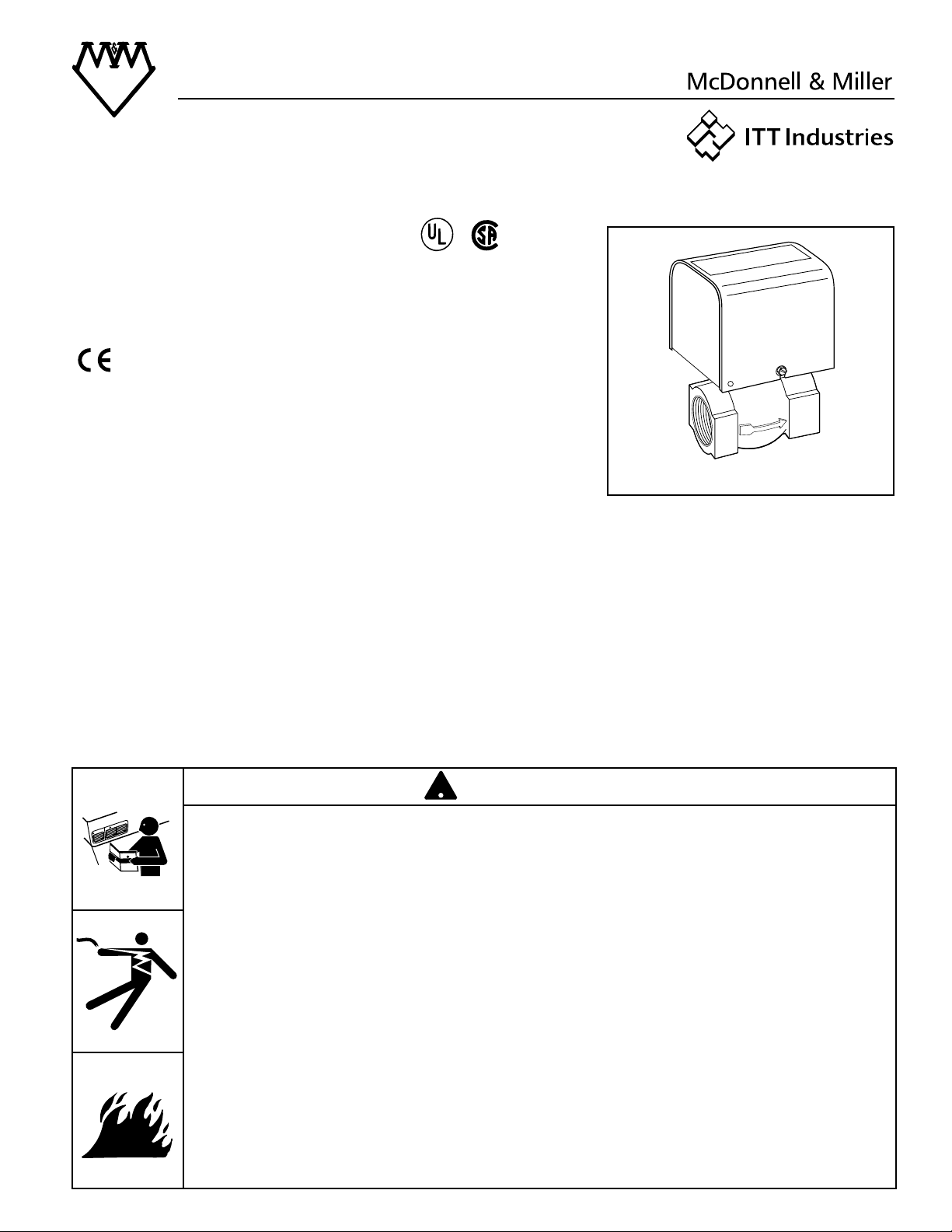
Series FS-5
General Purpose
Liquid Flow Switch
OPERATION
This control is an independently mounted water flow
sensing device that makes or breaks an electrical
circuit when flow stops or starts.
• Before using product, read and understand instructions.
• Save these instructions for future reference.
• All work must be performed by qualified personnel trained in the proper application,
installation, and maintenance of plumbing, steam and electrical equipment and/or systems in
accordance with all applicable codes and ordinances.
• To prevent electrical shock, turn off the electrical power before making electrical
connections.
• To prevent an electrical fire or equipment damage, electrical wiring insulation must have a
rating of 167˚F (75˚C) if the liquid’s temperature exceeds 180˚F (82˚C).
• To prevent electrocution, when the electrical power is connected to the flow switch, do not
touch the terminals.
• Make sure flow switch electrical cover is secured before turning on electric power.
Failure to follow this warning could cause property damage, personal injury or death.
W
A
R
N
I
N
G
C
A
U
T
I
O
N
!
WARNING
Series FS-5
(specified models only)
®
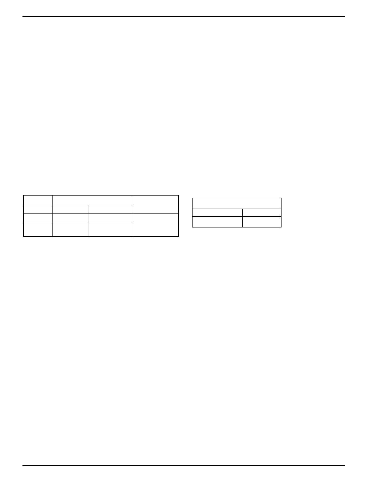
CE Circuit Rating
7.4 (7.4)/120~ 0.3/120=
3.7 (3.7)/240~ 0.15/240=
2
Motor Switch Rating (Amperes)
Voltage Full Load Locked Rotor Pilot Duty
120 VAC 7.4 44.4
125 VA at
240 VAC 3.7 22.2
120 or 240 VAC
50 or 60 cycles
Maximum Liquid Pressure: 150 psi (10.5 kg/cm2)
Liquid Temperature Range (T
L): 32 - 250˚F (0 - 121˚C) (All models except “S”)
32 - 225˚F (0 - 107˚C) (“S” models)
Ambient Temperature Range (TS): 32 - 120˚F (0 - 49˚C)
Electrical Enclosure Rating: Nema Type 1 (IP 21)
Maximum V elocity: 10ft/sec (3M/sec)
Pipe Connection Thread Size:
3
/4” or 1” NPT (All models except “J”)
3
/4” or 1” BSPT (“J” models)
Models that meet CE Conformance:
FS5-J-3/4-E
FS5-J-1-E
• This Control: is for continuous operations
is not electronic
has Type 1C action (micro interruption
on operation)
• LVD 73/23/EEC
• EMC 89/33/EEC
For applications with loads between 0.5 and 3.7 Amps,
power factors exceeding 0.65, an anticipated system
switch operation rate of less than once per 2.5 minutes,
and any one cycle greater than 3 seconds on and 3
seconds off.
For applications with loads 0.5 and 38mA, power
factors exceeding 0.65, an anticipated system
switch operation rate of less than once per 5 minutes,
and any one cycle greater than 3 seconds on and 3
seconds off.
Additional suppression may be required for applications outside these ranges.
• Declaration of Conformity
Available on request.
SPECIFICATIONS
ELECTRICAL RATINGS
FLOW RATES
Flow rates required to activate flow switch are shown
in chart below. The values are calculated for sensing
water (potable, non-polluted) in a horizontal pipe.
Settings will vary when used to sense flow of other
fluids.
3
NOTE: DO NOT USE LIQUID FLOW
SWITCHES ON SYSTEMS WITH
FLOW VELOCITY GREATER THAN
10 FEET (3M) PER SECOND.
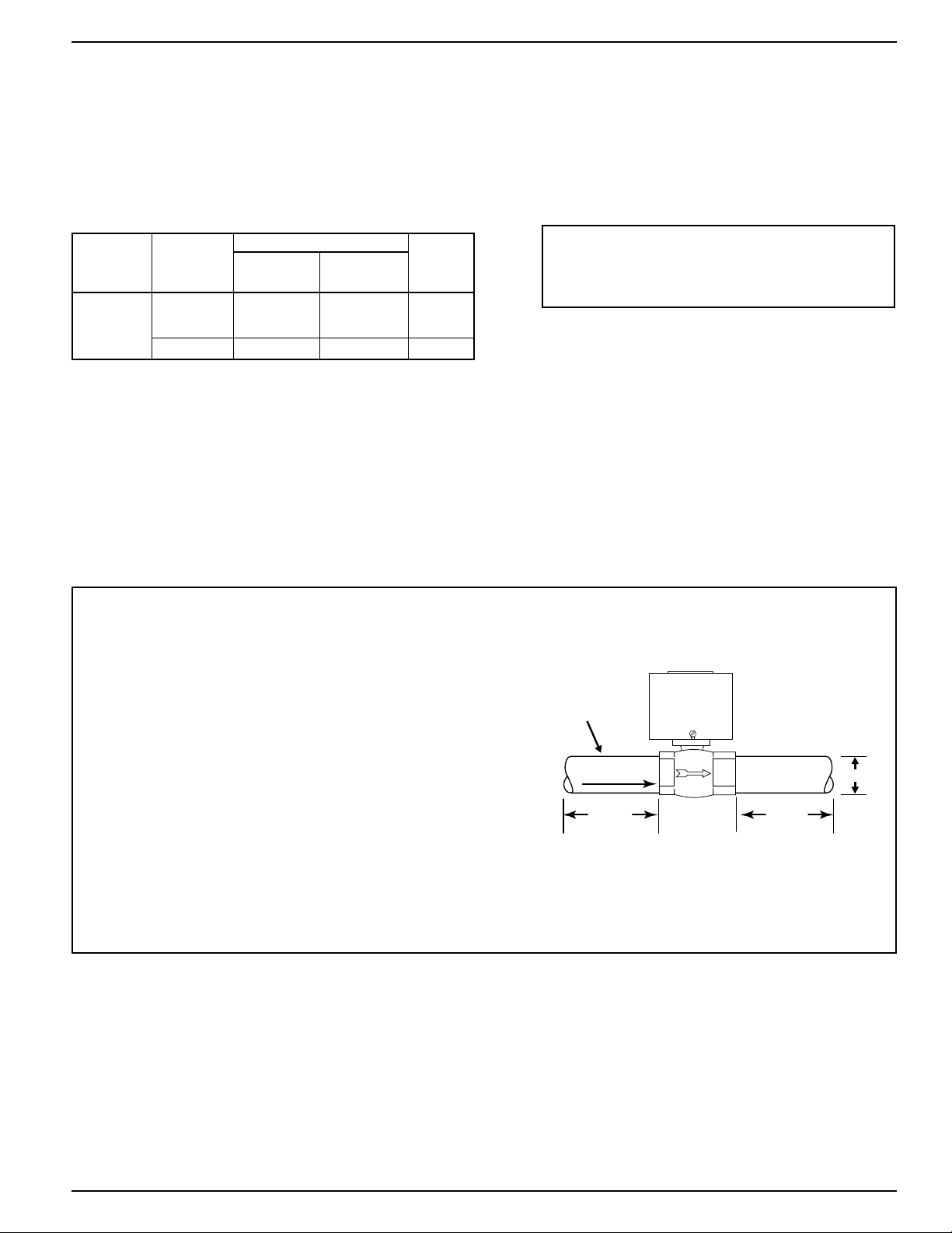
INSTALLATION –
STEP 1 - Determine the Location of the Flow Switch
Fluid Flow
3/4" or 1"
PIPE
5 x D
MINIMUM
D
D= PIPE DIAMETER
5 x D
MINIMUM
• The flow switch should be located in a horizontal
section of pipe where there is a straight horizontal run
of at least 5 pipe diameters on each side of the flow
switch.
• The flow switch must be installed in the upright
position as shown with arrow mark on side of casting
in the same direction as fluid will flow.
• Some system conditions that require more than 5 pipe
diameters are high viscosity fluid and high fluid velocity.
• The flow switch should be installed in the pump suction
piping when spring-loaded check valves and/or other
close coupled accessories are installed in the pump
discharge piping.
Flow Rates
Pipe
Mode of Operation
Size NPT Flow No Flow
in. (mm) Settings gpm (lpm) gpm (lpm)
3
⁄
4
(20)
Factory or
or Minimum 1.5 (5.7) 1.1 (4.2) 16.62 (63)
1 (25)
Maximum 15 (56.8) 10 (37.9) 27 (102)
Values are ±10%
Max. Flow
Rate gpm
(lpm) w/o
Paddle Damage
 Loading...