

MCDONALDS C844, C842 USER MANUAL
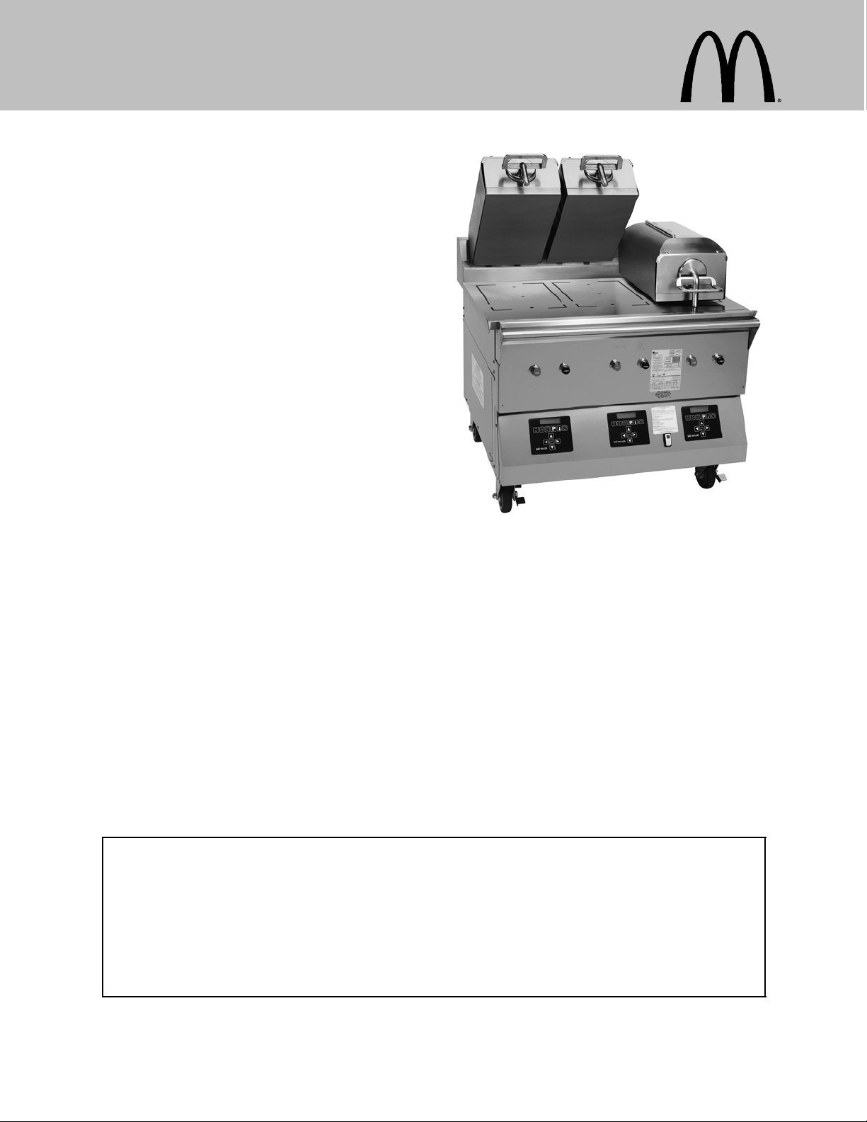
Clamshell Grill
Models C842 & C844
Place this chapter in the Grill section
of the Equipment Manual.
Manufactured exclusively for
McDonald's® by
Taylor Company
750 N. Blackhawk Blvd.
Rockton, IL 61072
Phone: (815) 624-8333
Toll Free Number
Outside Illinois:
1 (800) 228-8309
Inside Illinois:
1 (800) 851-5639
Fax: (815) 624-8000
Table of Contents
Introduction Page 1.....................................................
Safety Page 1..........................................................
Parts Identifications/Functions Page 4.....................................
Important to the Operator Page 12.........................................
Equipment Set Up Procedures Page 14.....................................
Menu Screens Page 16...................................................
Closing Procedures Page 22..............................................
Troubleshooting Guide Page 31............................................
Ordering/Service Information Page 34......................................
Non-Scheduled Maintenance Page 35......................................
System Set-up Page 35...................................................
Menu Items Page 40.....................................................
Auto Leveling Page 48....................................................
Wiring Diagrams Page 49.................................................
Warranty
A warranty checkout card is shipped with all new equipment that leaves the factory. The warranty checkout card is
packedinan envelopewhichalsocontainsthisoperator'smanual.Refertothewarrantycheckoutcardandthewarranty
classifications listedin the Parts Identification/Function section when service is performed on your machine.
Itisrecommendedthattheoperatortake the necessarytimetocarefullyreadthroughthecomplete warrantyinformation
contained in the warranty checkout card. Any questions or unclear statements found within the card should be made
clearto youupondeliveryofthemachine.Thoroughlyunderstandyourwarrantyprotectionbeforeyou begin operation.
For any questions pertaining to the Taylor Warranty, please contact your authorized Taylor Distributor, or Taylor
Company, Rockton, Illinois 61072.
This manual is for the exclusive use of licensees and employees of McDonald's Corporation.
E2010 McDonald's Corporation
All Rights Reserved
January, 2010 (Original Publication)
(Updated January, 2011)
EM SD11
The United States of America
Printed in

INTRODUCTION
The Models C842 and C844 have three
independent upper platens. These grills
provide automatic leveling of the platens.
The grills are capable of cooking a variety of
products and feature two cooking options,
AUTO and MANUAL.
AUTO Option: The grills automatically detect
the product placed on the grill plate (menu
items that are cooked using the clamshell,
only) and set the appropriate cooking
parameters.
MANUAL Option: After the operator selects
the desired product to be cooked, the grills
automatically set the appropriate cooking
parameters.
These grills provide all of the features of a flat
grill, as well as the advantages of two-sided
cooking.
Per IEC 60335-1 and its part 2
standards, “This appliance is to be used only
by trained personnel. It is not intended for use
by children or people with reduced physical,
sensory, or mental capabilities, or lack of
experience and knowledge, unless given
supervision or instruction concerning the use
of the appliance by a person responsible for
their safety.”
DO NOT install the unit in an area
where a water jet could be used. DO NOT use
a water jet to clean or rinse the grill. Failure to
follow this instruction may result in serious
electrical shock. In addition, water may collect
inside the grill and destroy electrical
components and cause injury from hot steam.
DO NOT operate the grill unless it is
properly grounded. Failure to comply may
result in equipment damage or personal injury.
All repairs must be performed by an
authorized Taylor service agent. The main
power supplies to the grill must be
disconnected prior to performing any repairs.
Note: These grills are designed for indoor
use only.
SAFETY
Always follow these safety precautions when
operating the grill:
DO NOT operate the grill without
reading this operator's manual. Failure to
comply may result in equipment damage or
personal injury. This manual should be kept in
a safe place for future reference.
This unit is provided with an equipotential
grounding lug that is to be properly attached to
the rear of the frame by the authorized
installer. The installation location is marked by
the equipotential bonding symbol (5021 of IEC
60417-1) on both the removable panel and the
equipment's frame.
S DO NOT operate the grill with larger
fuses than specified on the data label.
S All repairs must be performed by an
authorized Taylor service agent. The
main power supplies to the grill must
be disconnected prior to performing
any repairs.
S Cord Connected Units: Only Taylor
authorized service technicians may
install a plug on these units.
1
101220
S Stationary appliances which are not
equipped with a power cord and a plug
or other device to disconnect the
appliance from the power source must
have an all-pole disconnecting device
with a contact gap of at least 3 mm
installed in the external installation.
S Appliances that are permanently
connected to fixed wiring and for which
leakage currents may exceed 10 mA,
particularly when disconnected or not
used for long periods, or during initial
installation, shall have protective
devices such as a GFI, to protect
against the leakage of current, installed
by the authorized personnel to the
local codes.
S Supply cords used with this unit shall
be oil-resistant, sheathed flexible cable
not lighter than ordinary
polychloroprene or other equivalent
synthetic elastomer-sheathed cord
(Code designation 60245 IEC 57)
installed with the proper cord
anchorage to relieve conductors from
strain, including twisting, at the
terminals and protect the insulation of
the conductors from abrasion.
Failure to follow these instructions may result
in personal injury, equipment damage, or poor
grill performance.
WARNING: Improper installation, adjustment, alteration, service or maintenance
can cause property damage, injury or
death. Read the installation, operating
and maintenance instructions thoroughly
before installing or servicing this equipment.
S This appliance must be isolated from
all combustible construction and
materials including, but not limited to;
walls, partitions, furniture, floors,
curtains, paper, boxes, and
decorations. Failure to comply may
result in fire and cause destruction and
severe injury.
FORYOURSAFETY
Do not store or use gasoline or other
flammable vapors or liquids in the vicinity
of this or any other appliance.
S DO NOT obstruct the ventilation
openings at the rear of this appliance.
S DO NOT obstruct the flow of air in and
around the grill.
S DO NOT operate the grill unless all
service panels and access doors are
attached with screws. Failure to comply
may result in personal injury from gas
or electrical components.
USE EXTREME CAUTION while
setting up, operating, and cleaning the grill.
Avoid coming in contact with the hot grill
surfaces or with the hot grease. Failure to
comply will result in burn injuries.
2
S The grill must be placed on a level
surface.
S To ensure thorough cleaning, the grill
must be pulled away from the wall.
When returning the grill to its original
position, use extreme caution to
smoothly and slowly roll the grill
backward into place.
Failure to follow these instructions may cause
the grill to tip and can result in severe
equipment damage or personal injury.
NOISE LEVEL: Airborne noise emission does
not exceed 70 dB(A) when measured at a
distance of 1.0 meter from the surface of the
machine and at a height of 1.6 meters from
the floor.
These instructions are valid only if the country
code symbol appears on the appliance. If the
symbol does not appear on the appliance,
refer to the technical instructions which give
the necessary instructions for adapting the
appliance to the utilization conditions of that
country.
NOTICE all warning labels that have
been attached to the grill to further point out
safety precautions to the operator.
HAZARD COMMUNICATION STANDARD
(HCS) - The procedure(s) in this manual
include the use of chemical products.
These chemical products will be
highlighted with bold faced letters followed
by the abbreviation (HCS) in the text
portion of the procedure. See the Hazard
Communication Standard (HCS) manual for
the appropriate Material Safety Data
Sheet(s) (MSDS).
This piece of equipment is made in America
and has American sizes on hardware. All
metric conversions are approximate and vary
in size.
If the crossed out wheeled bin symbol
is affixed to this product, it signifies that this
product is compliant with the EU Directive as
well as other similar legislation in effect after
August 13, 2005. Therefore, it must be
collected separately after its use is completed,
and cannot be disposed as unsorted municipal
waste.
The user is responsible for returning the
product to the appropriate collection facility, as
specified by your local code.
For additional information regarding applicable
local laws, please contact the municipal facility
and/or local distributor.
3
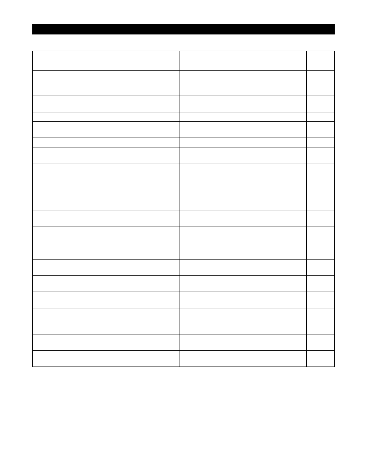
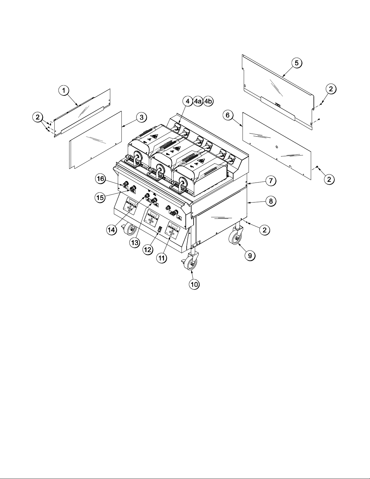
PARTS IDENTIFICATION/FUNCTIONS
C842 Exploded View (See Figure 1.)
ITEM
1 X72962 Panel A.-Side Upper
PART NO. DESCRIPTION QTY. FUNCTION WARR.
1 Provides access to internal com-
Left
ponents for service and cleaning.
2 024298 Screw-10-32 X 3/8 6 Secures the panel to the frame. 000
3 072967 Panel-Side Left 1 Provides access to internal com-
ponents for service and cleaning.
4 X78330-SER Kit A.-Grease Shield 3 Prevents grease migration. 103
4a 078329 Fastener-Snap in 1/4 x
15/16
24 Fastens the grease shield to the
grill.
4b 078285 Shield-Grease 4 Prevents grease migration. 000
5 X72951 Panel A.-Back Service
(Upper)
6 X72958-SER
(Includes
Panel A.-Back Panel
(Lower)
1 Provides access to internal com-
ponents for service and cleaning.
1 Provides access to internal com-
ponents for service and cleaning.
6a-6e)
6a 072959 Panel-Back 2 Speed
Fan
1 Provides access to internal com-
ponents. Has a two speed fan
connector built into the panel.
6b 053889 Cap-Protective Plastic
7/8 THD
1 Protects the plug on the end of
the back panel harness.
6c X74158 Harness A.-Back Pnl 1 Connects to the internal harness
in the grill for the 2 speed fan.
6d 078327 Nut-Locking Conduit
1/2”
1 Secures the back panel harness
connector to the panel.
6e 044823 Connector-Mate Lock 1 Connects the back panel harness
to the internal wire harness.
7 X72965 Panel A.-Side Upper
Right
8 072968 Panel-Side Right
(Lower)
1 Provides access to internal com-
ponents for service and cleaning.
1 Provides access to internal com-
ponents for service and cleaning.
9 078377 Caster-5” 7-5/8 Stem 2 Allows grill mobility. 103
10 073240 Caster-5” Swivel
2 Prevents grill movement. 103
w/Lock
11 X72491-SER Control-Display Inter-
3 Controls all functions of the grill. 103
face
12 076989-WP Switch-Rocker-DPST
10A (Fan Interlock)
1 Activates power to the grill and
the exhaust fans.
CLASS
103
103
000
103
103
103
000
103
000
103
103
103
103
4
110218

C842 Exploded View
ITEM
PART NO. DESCRIPTION QTY. FUNCTION WARR.
13 076012 Button-Operator-Black
(Standby)
14 076011 Button-Operator-Red
(Raise)
3 Activates the cook cycle, keeps
the upper platen in the closed po-
sition, and displays the message
“STANDBY” on the control. When
pressed twice within five
seconds, the upper platen will
automatically lower into the
Standby position.
3 Cancels the Standby mode,
raises the upper platen, and de-
activates the Cook cycle.
CLASS
000
000
Figure 1
5
110218
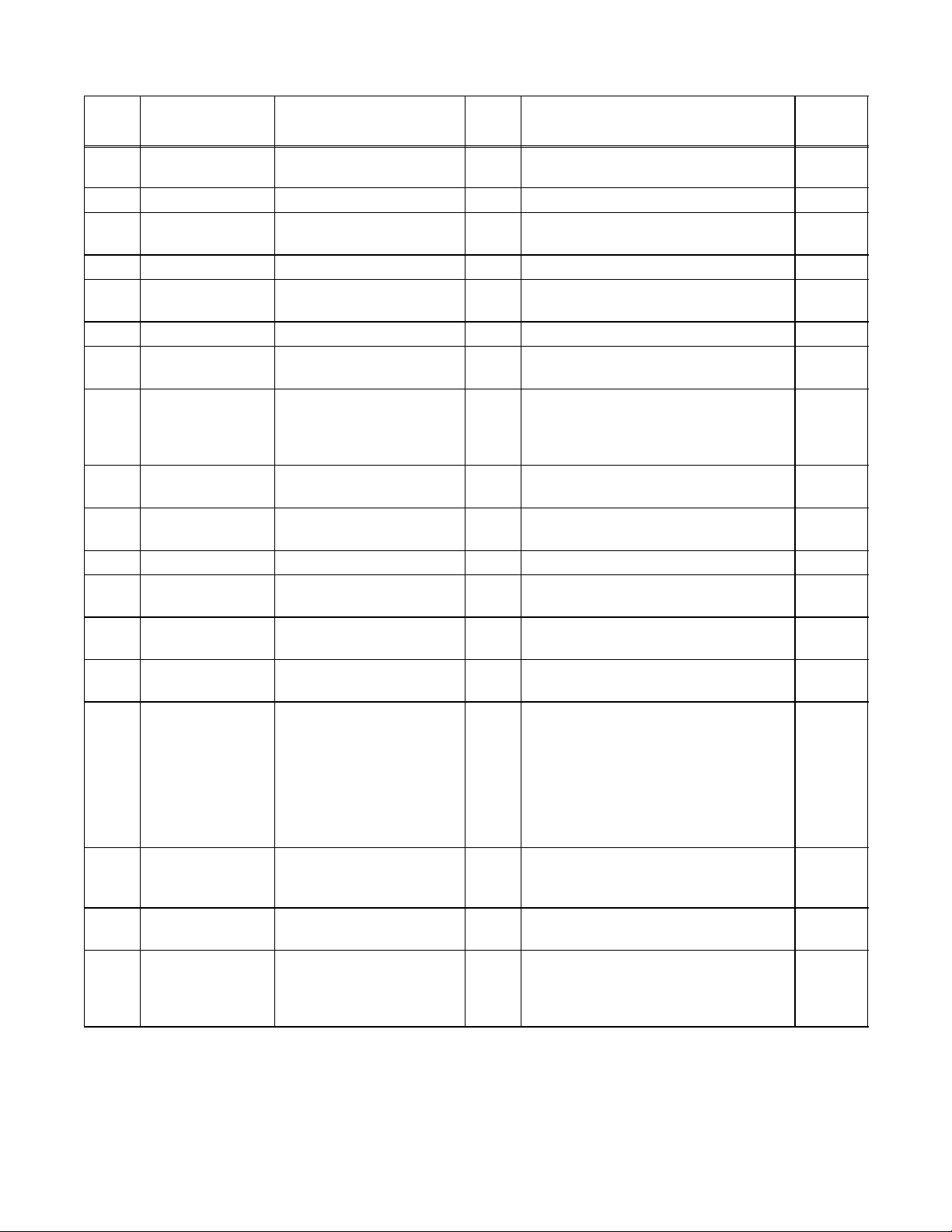
C844 Exploded View (See Figure 2.)
ITEM
1 X72786 Panel A.-Side Upper
PART NO. DESCRIPTION QTY. FUNCTION WARR.
1 Provides access to internal com-
Left
ponents for service and cleaning.
2 024298 Screw-10-32 X 3/8 6 Secures the panel to the frame. 000
3 072790 Panel-Side Left 1 Provides access to internal com-
ponents for service and cleaning.
4 X78330-SER Kit A.-Grease Shield 3 Prevents grease migration. 103
4a 078329 Fastener-Snap in 1/4 x
15/16
24 Fastens the grease shield to the
grill.
4b 078285 Shield-Grease 4 Prevents grease migration. 000
5 X72951 Panel A.-Back Service
(Upper)
6 072959 Panel-Back 2 Speed
Fan
1 Provides access to internal com-
ponents for service and cleaning.
1 Provides access to internal com-
ponents for service and cleaning.
Has a two speed fan connector
built into the panel.
7 X72788 Panel A.-Side Upper
Right
8 072791 Panel-Side Right
(Lower)
1 Provides access to internal com-
ponents for service and cleaning.
1 Provides access to internal com-
ponents for service and cleaning.
9 078377 Caster-5” 7-5/8 Stem 2 Allows grill mobility. 103
10 073240 Caster-5” Swivel
2 Prevents grill movement. 103
w/Lock
11 X72491-SER Control-Display Inter-
3 Controls all functions of the grill. 103
face
12 076989-WP Switch-Rocker-DPST
10A (Fan Interlock)
13 076012 Button-Operator-Black
(Standby)
1 Activates power to the grill and
the exhaust fans.
3 Activates the cook cycle, keeps
the upper platen in the closed po-
sition, and displays the message
“STANDBY” on the control. When
pressed twice within five
seconds, the upper platen will
automatically lower into the
Standby position.
14 076011 Button-Operator-Red
(Raise)
3 Cancels the Standby mode,
raises the upper platen, and de-
activates the Cook cycle.
15 075288 Guard-Lense 3 Protects the Standby button from
being accidently activated.
16 075699SYM3 Label-Control Panel-
International Symbol
1 Set of labels located under the
Raise button (showing platen
raising) and Standby button
(showing platen lowering).
CLASS
103
103
000
103
103
103
103
103
000
000
103
000
6
110218
C844 Exploded View
Figure 2
7
110218
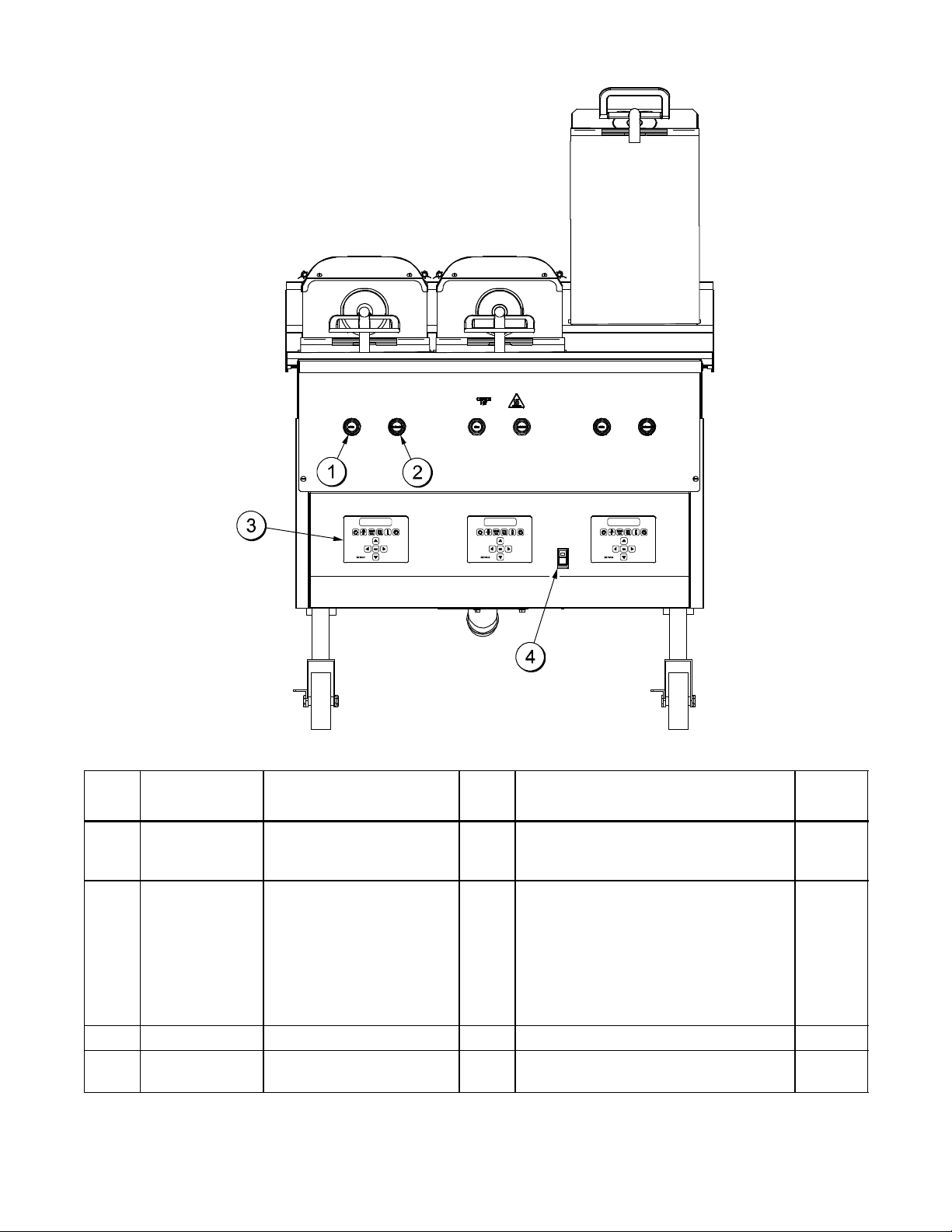
C842/C844 Front View
Figure 3
ITEM PART NO. DESCRIPTION QTY. FUNCTION WARR.
CLASS
1 076011 Button-Operator-Red
(Raise)
3 Cancels the Standby mode, raises
the upper platen, and deactivates
000
the Cook cycle.
2 076012 Button-Operator-Black
(Standby)
3 Activates the cook cycle, keeps
the upper platen in the closed
000
position, and displays the
message “STANDBY” on the
control. When pressed twice
within five seconds, the upper
platen will automatically lower into
the Standby position.
3 X72491-SER Control-Display 3 Controls all functions of the grill. 103
4 076989-WP Switch-Rocker-DPST
10A (Fan Interlock)
1 Activates power to the grill and the
exhaust fans.
8
103
101020
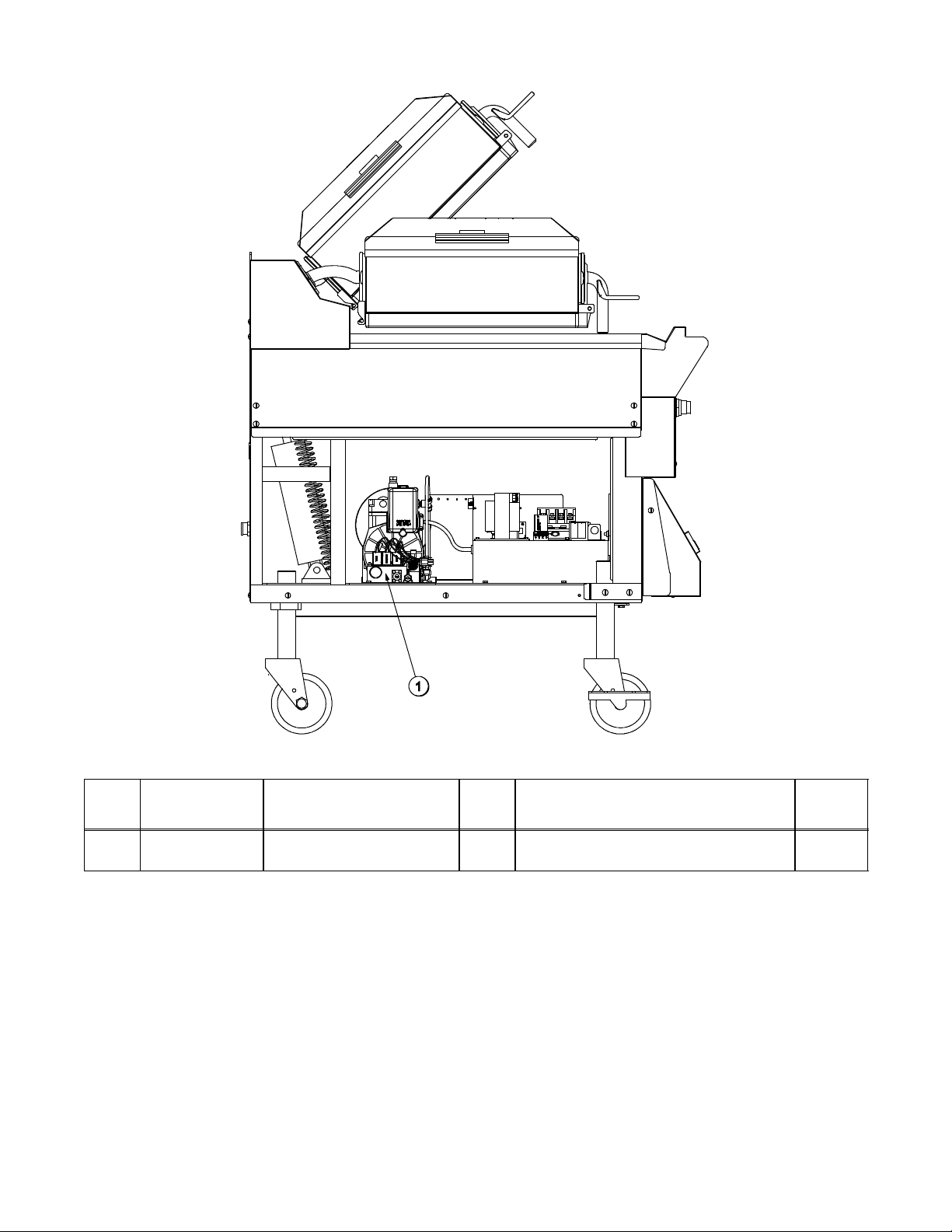
C842/C844 Right Side View
Figure 4
ITEM PART NO. DESCRIPTION QTY. FUNCTION WARR.
CLASS
1 072472 Handle-Platen 3 The handle sits solidly on the
103
lower cook surface when the
platen is lowered.
9
100607
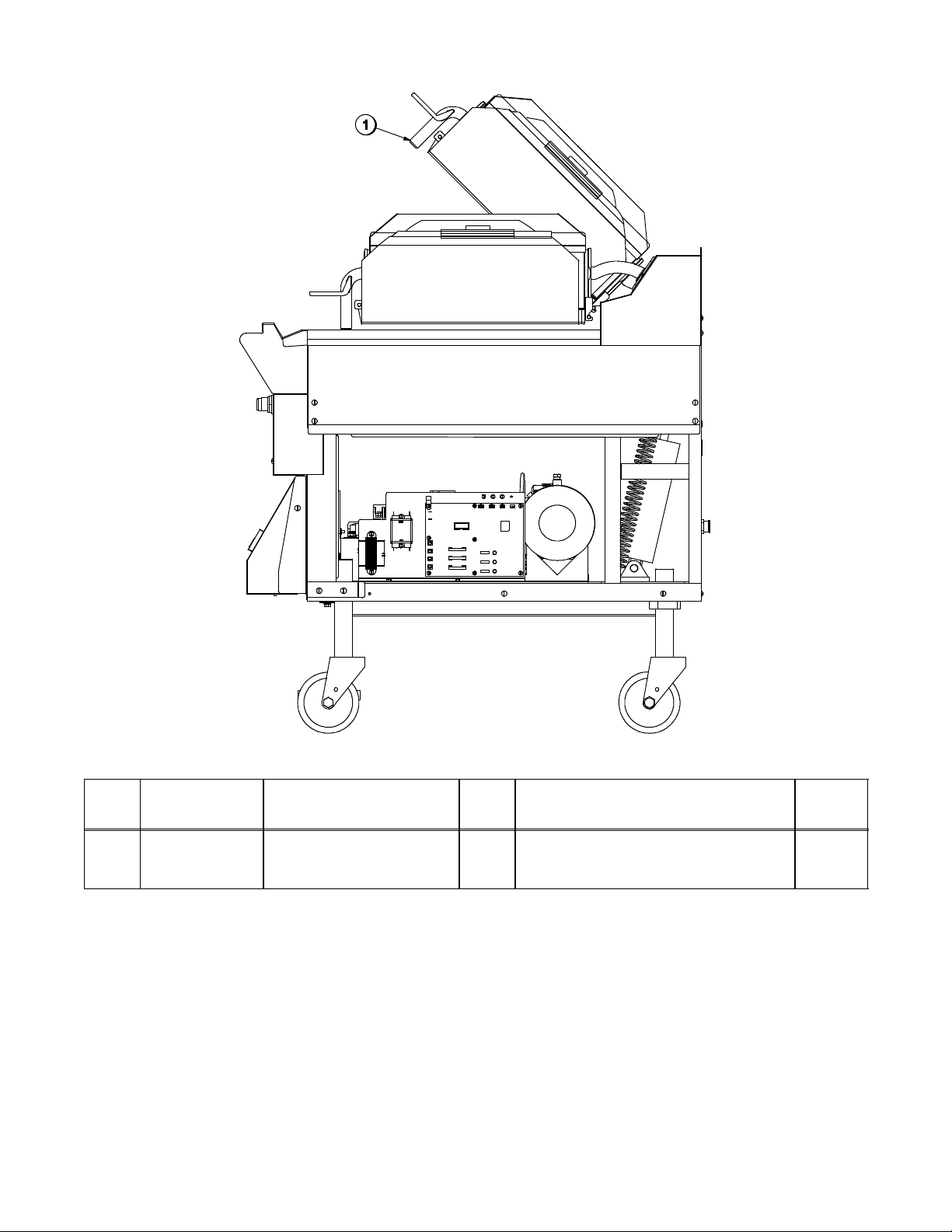
C842/C844 Left Side View
Figure 5
ITEM PART NO. DESCRIPTION QTY. FUNCTION WARR.
CLASS
1 072695 Manifold A. 1 Regulates air pressure for platen
103
operation.
10
100607

C842/C844 Accessories
ITEM
PART NO. DESCRIPTION QTY. FUNCTION WARR.
1 073338 Rod-Release Material 3 Secures the hemmed end of the
release material sheet to the rear
of the platen.
2 072673 Clip-Release Material
w/Tab
9 Secures the release material
sheet to the front and sides of the
platen.
3 073337 Sheet-Release
Box of 9
1 Non-stick barrier used to protect
the upper platen.
CLASS
000
000
000
Figure 6
11
100804
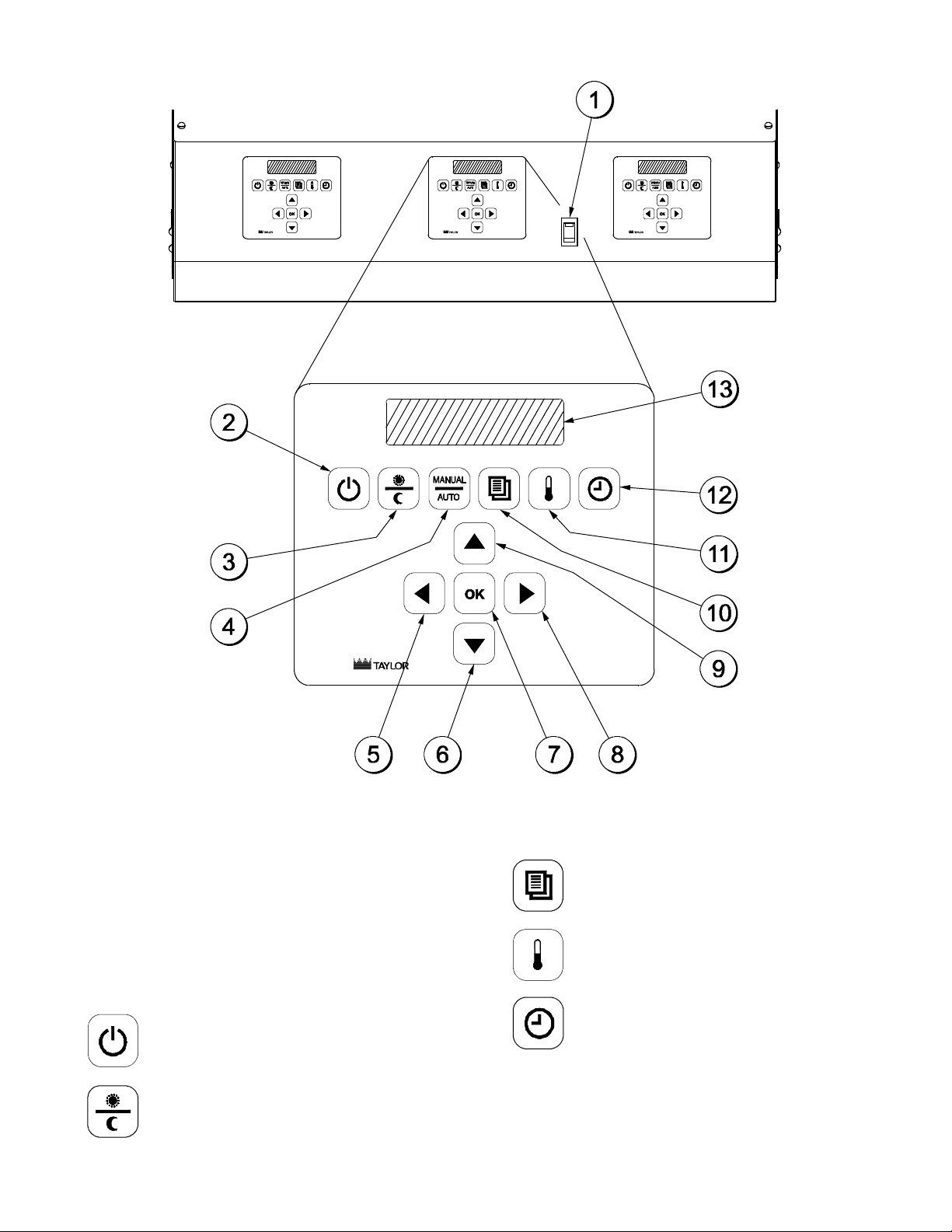
IMPORTANT TO THE OPERATOR
Important to the Operator Parts Identification (See Figure 7.)
ITEM
DESCRIPTION FUNCTION
1 Fan Interlock Switch This switch activates power to the grill and the exhaust fans.
2 ON/OFF Key This key is used to turn the controller on and off to start a
preheating mode and to auto-gap the platen. The key must be
pressed and held for three seconds to activate, in o rder to
prevent unintended operation.
3 AM/PM Key This key is used to toggle back and forth between the AM and PM
menu item lists.
4 MANUAL/AUTO Key This key is used to toggle back and forth between the Manual
and Auto modes.
5 Left Arrow Key This key is used to scroll through menu items when cooking in the
Manual mode. (Inactive in the Auto mode.)
6 Down Arrow Key While in the Menu mode, this key is used to decrease a numerical
value and to scroll through the characters when entering a new
menu item or modifying an old one. (Inactive in the Auto mode.)
7 OK Key This key is used to accept the information entered.
8 Right Arrow Key This key is used to scroll through menu items when cooking in the
Manual mode. (Inactive in the Auto mode.)
9 Up Arrow Key While in the Menu mode, this key is used to increase a numerical
value and to scroll through the characters when entering a new
menu item or modifying an old one. (Inactive in the Auto mode.)
10 Program Key This key is used to enter and exit the Programming mode.
11 Temperature Key When pressed and held for 3 seconds, this key will access the
Probe Calibration screen.
12 Cook Time Key This key is used to change the remove time of a specific menu
item. To change a specific cook time, the item must be selected in
the Manual mode. (Note: Press and hold the Cook Time key for
three seconds to activate.)
13 Liquid Crystal Display This screen displays menu options and information.
12
Important to the Operator
Symbol Definitions
To better communicate in the International
arena, the words on many of our operator
keys have been replaced by symbols to
indicate their functions. Your Taylor equipment
is designed with these International symbols.
The following chart identifies the symbol
definitions.
= ON/OFF
=AM/PM
Figure 7
= PROGRAM
= TEMPERATURE
=TIME
13
EQUIPMENT SET-UP PROCEDURES
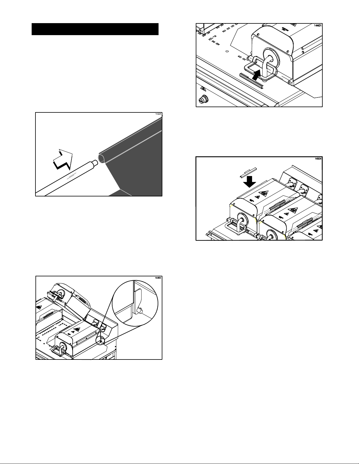
Installing Release Material Sheets
1. Slide the release material retention bar
through the loop in the release sheet.
(See Figure 8.)
Figure 10
4. Carefully rotate the release sheet side
flaps over the cover rails and secure the
sheet with locking clips. (See Figure 11.)
Figure 8
2. Engage the material retention bar into the
hooks provided on the shroud.
(See Figure 9.)
Figure 9
3. Center the release sheet on the bar. Pull
it tightly over the release material bar
located in the front of the shroud. Secure
the sheet with a locking clip.
(See Figure 10.)
Figure 11
IMPORTANT! Do not crease the release
sheet. This will greatly reduce the life
of the sheet.
5. Make sure the release sheets are tight
across the upper platen surface.
6. Repeat these steps for the other upper
platens.
The release sheet must be changed when:
S Product sticks to the release sheet.
S Carbon builds up, causing problems in
taste or appearance.
S There is a tear in the release sheet in
the cooking area.
S The release material substance is worn
from the release sheet.
Note: Rotate and reverse the release sheets
on a daily basis.
14
100813
Care of Release Material Sheets
S DO NOT fold or crease.
S DO NOT touch with any sharp object or
abrasive.
S DO NOT hose with hot water or soak in
water.
S DO NOT place under other objects.
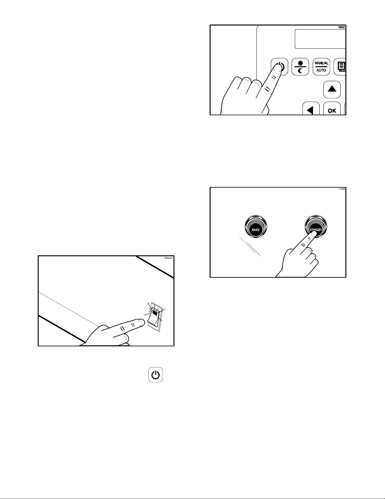
Start-Up of the Grill
IMPORTANT! The lower grill plate and the
upper platen MUST BE CLEAN before
starting these procedures.
Figure 13
3. The control will first display, “CLEAN
GRILL SURFACES”. Then the control will
display, “CLOSE THE CLAM FOR AUTO
LEVELING.”
4. Press the Standby button to close the
platen. (See Figure 14.)
1. Place the fan interlock switch in the ON
position. The controller will display the
message “OFF”. (See Figure 12.)
Figure 12
2. Heat up the grill by pressing the key
for 3 - 5 seconds. “AM TOO COOL” and
“AM FOLDED EGGS - FLAT” will be
displayed on the control screen.
(See Figure 13.)
Figure 14
5. After the platen has closed, the grill will
start heating up to the proper
temperature. The control will display the
following message until the grill has
reached the proper temperature, ”TOO
COOL FOR AUTO LEVELING”.
6. When the grill has reached the proper
temperature, the screen will display,
“PLEASE WAIT FOR AUTO LEVELING”.
7. When the Auto Leveling is complete, the
upper platen will raise. The screen will
display the product that had been
selected.
15
 Loading...