

McDonald's 6000XL, 6100XL Operation Manual

6000XL
The Delfield Company Models 6000XL & 6100XL
Operation Manual
Manufactured exclusively for
McDonald’s® By:
Delfield
980 S. Isabella Rd.
Mt. Pleasant, MI 48858
Tel. (989) 773-7981 Fax (888) 779-2040
6000XL Refrigerators and Freezers
Note: Do not install these unit(s) in any area with an ambient temperature in excess of
95°F/35°C. Doing so will cause damage to the unit(s).
*9294284*
Printed in July 2013
The United States of America
Printed in
6000XL Series Service and Installation Manual
Delfield
Important Warning And Safety Information
WARNING Read This Manual Thoroughly Before Operating, Installing, Or Performing Maintenance On The Equipment.
WARNING Failure To Follow Instructions In This Manual Can Cause Property Damage, Injury Or Death.
WARNING Do Not Store Or Use Gasoline Or Other Flammable Vapors Or Liquids In The Vicinity Of This Or Any Other
Appliance.
WARNING Unless All Cover And Access Panels Are In Place And Properly Secured, Do Not Operate This Equipment.
WARNING This Appliance Is Not Intended For Use By Persons Who Lack Experience Or Knowledge, Unless They Have
Been Given Supervision Or Instruction Concerning Use Of The Appliance By A Person Responsible For Their
Safety.
WARNING This Appliance Is Not To Be Played With.
WARNING Do Not Clean With Water Jet.
WARNING Do Not Use Electrical Appliances Inside The Food Storage Compartment Of This Appliance.
CAUTION Observe the following:
• Minimum clearances must be maintained from all walls and combustible materials.
• Keep the equipment area free and clear of combustible material.
• Allow adequate clearance for air openings.
• Operate equipment only on the type of electricity indicated on the specification plate.
• Unplug the unit before making any repairs.
• Retain this manual for future reference.
2
For customer service, call (800) 733-8829, (800) 733-8821, Fax (888) 779-2040, www.delfield.com
™
®

Delfield
Contents
Receiving & Inspecting Equipment ...........................................3
Serial Number Information ........................................................ 4
Warranty Information ................................................................. 4
Regulatory Certifications ............................................................ 4
Specifications ............................................................................. 5
Installation .................................................................................. 6
Door Reversal Procedures ......................................................... 7
Leg & Caster Installation ............................................................7
Operation .................................................................................8-9
Evaporator Fan Matrix ................................................................ 9
Maintenance ........................................................................10-11
PM Cover Page ........................................................................12
Daily Inspect & Clean PM Card ...............................................13
Quarterly Clean Condenser Coil PM Card ................................ 14
Quarterly Inspect Door Gaskets PM Card ...............................15
Wiring Diagrams .................................................................16-20
Refrigeration Package Diagram ............................................... 21
Replacement Parts ..............................................................22-23
Standard Labor Guidelines ......................................................24
Notes ...................................................................................25-27
6000XL Series Service and Installation Manual
Receiving And Inspecting The Equipment
Even though most equipment is shipped crated, care should
be taken during unloading so the equipment is not damaged
while being moved into the building.
1. Visually inspect the exterior of the package and skid or
container. Any damage should be noted and reported to
the delivering carrier immediately.
2. If damaged, open and inspect the contents with the
carrier.
3. In the event that the exterior is not damaged, yet upon
opening, there is concealed damage to the equipment
notify the carrier. Notification should be made verbally
™
®
as well as in written form.
4. Request an inspection by the shipping company of the
damaged equipment. This should be done within 10
days from receipt of the equipment.
5. Be certain to check the compressor compartment
housing and visually inspect the refrigeration package.
Be sure lines are secure and base is still intact.
6. Freight carriers can supply the necessary damage forms
upon request.
7. Retain all crating material until an inspection has been
made or waived.
For customer service, call (800) 733-8829, (800) 733-8821, Fax (888) 779-2040, www.delfield.com
3
6000XL Series Service and Installation Manual
Delfield
Serial Number Information
The serial number tag of all 6000XL Series refrigerators and
freezers is located inside the cabinet on the left side.
Always have the serial number of your unit available when
calling for parts or service. A complete list of authorized
Delfield parts depots is available at www.delfield.com.
This manual covers standard units only. If you have a custom
unit, consult the customer service department at the number
listed below.
©2013 The Delfield Company. All rights reserved. Reproduction without
written permission is prohibited. “Delfield” is a registered trademark of The
Delfield Company.
Warranty Information
Visit http://www.delfield.com/minisite/service/warranty_info to:
• Register your product for warranty.
• Verify warranty information.
• View and download a copy of your warranty.
Regulatory Certifications
The models are certified by:
National Sanitation Foundation (NSF)
Underwriters Laboratories (UL)
4
For customer service, call (800) 733-8829, (800) 733-8821, Fax (888) 779-2040, www.delfield.com
™
®
Delfield
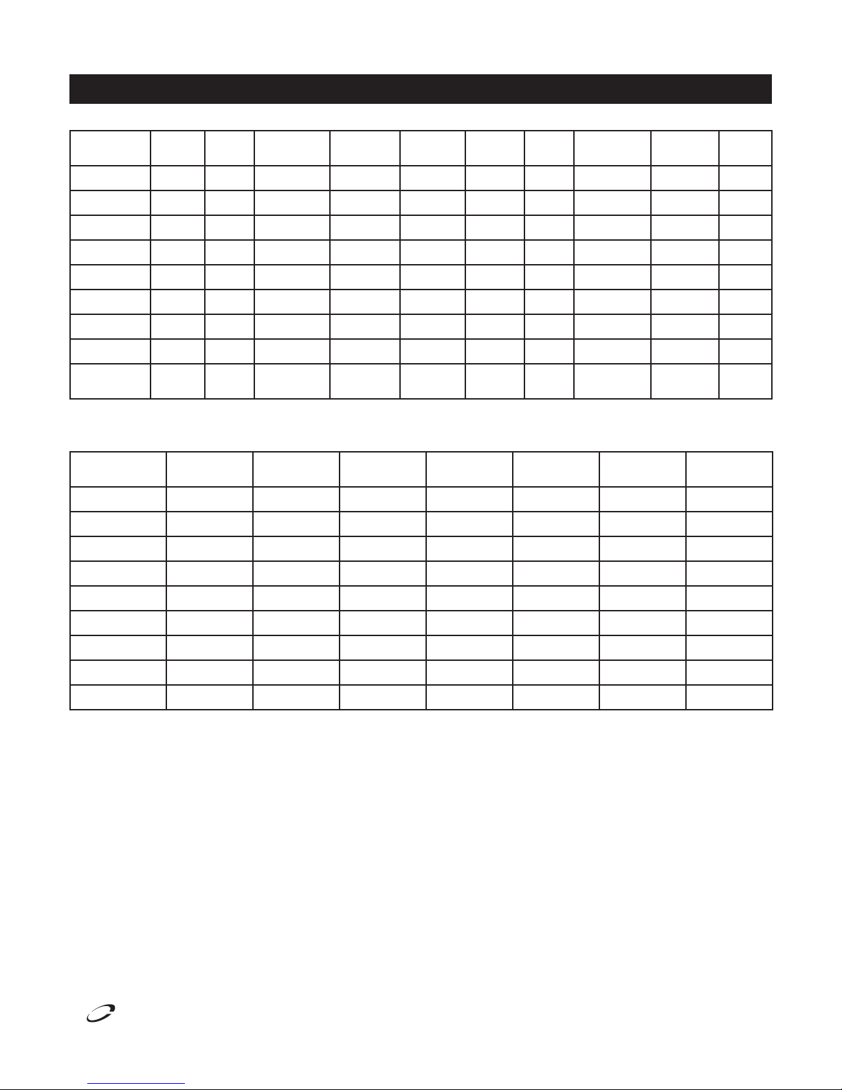
Specifications
6000XL Series Service and Installation Manual
Model Voltage Amps
6025XL-SH,S 115 6.0 20.0 15.1 1/4 2092 20˚F 12.5 274lbs/124kg 515P
6025XL-G,GH 115 6.0 20.0 15.1 1/4 2092 20˚F 12.5 338lbs/153kg 515P
6051XL-SH,S 115 8.0 43.5 33.2 1/3 2488 20˚F 12.5 454lbs/206kg 515P
6051XL-G,GH 115 8.0 43.5 33.2 1/3 2488 20˚F 12.5 548lbs/249kg 515P
6076XL-SH,S 115 16.0 66.5 48.3 1/4, 1/3 2092/2488 20˚F 12.5/12.5 622lbs/282kg 520P
6076XL-G,GH 115 16.0 66.5 48.3 1/4, 1/3 2092/2488 20˚F 12.5/12.5 774lbs/351kg 520P
6125XL-S,SH 115 9.0 20.0 15.1 1/2 2092 -20˚F 12.5 274lbs/124kg 515P
6151XL-S,SH 115 12.0 43.5 33.2 3/4 1923 -20˚F 12.5 454lbs/206kg 515P
6176XL-S,SH
Model Voltage Amps
6025XLR-SH,S 115 5.0 20.0 15.1 2092 20˚F 274lbs/124kg
6025XLR-G,GH 115 5.0 20.0 15.1 2092 20˚F 338lbs/153kg
120/208-
230
20.0 66.5 48.3 1/2, 3/4 1516/1923 -20˚F 12.5/12.5 622lbs/282kg 1420P
Storage
Capacity FT
3
Shelf
Capacity FT
Storage
Capacity FT
2
3
H.P. BTU/HR
Shelf
Capacity FT
2
Evap.
Temp
Required
BTU/HR
R-404A Charge
Oz.
Evap. Temp Shipping Weight
Shipping
Weight
Nema
Plug
6051XLR-SH,S 115 5.0 43.5 33.2 2488 20˚F 454lbs/206kg
6051XLR-G,GH 115 5.0 43.5 33.2 2488 20˚F 548lbs/249kg
6076XLR-SH,S 115 5.0 66.5 48.3 2092/2488 20˚F 622lbs/282kg
6076XLR-G,GH 115 5.0 66.5 48.3 2092/2488 20˚F 774lbs/351kg
6125XLR-S,SH 115 5.0 20.0 15.1 2092 -20˚F 274lbs/124kg
6151XLR-S,SH 115 5.0 43.5 33.2 1923 -20˚F 454lbs/206kg
6176XLR-S,SH 115 5.0 66.5 48.3 1516/1923 -20˚F 622lbs/282kg
™
®
For customer service, call (800) 733-8829, (800) 733-8821, Fax (888) 779-2040, www.delfield.com
5
6000XL Series Service and Installation Manual
Delfield
Installation
Location
Units represented in this manual are intended for indoor use
only. Be sure the location chosen has a floor strong enough
to support the total weight of the cabinet and contents. A fully
loaded 6000XL series can weigh as much as 1500 pounds.
Reinforce the floor as necessary to provide for maximum
loading. For the most efficient refrigeration, be sure to provide
good air circulation inside and out.
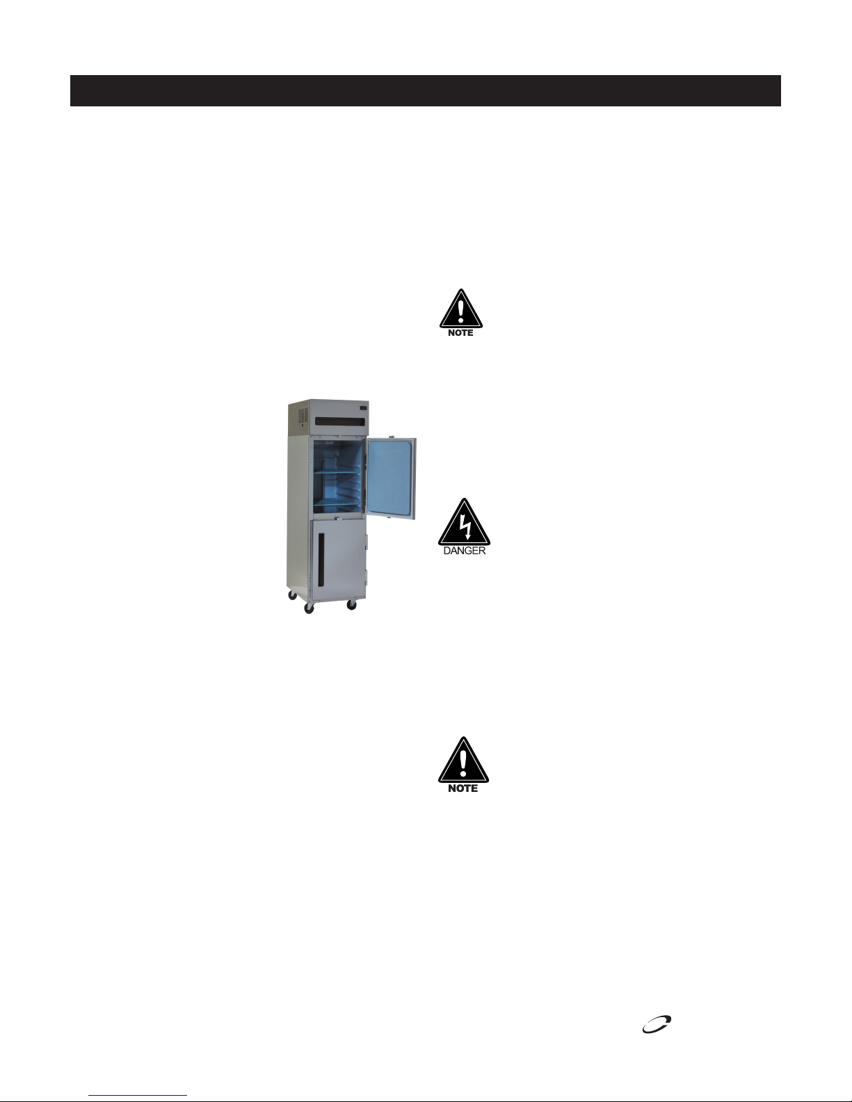
Inside cabinet: Do not pack refrigerator so full that air cannot
circulate. The refrigerated air is discharged at the top rear of
the unit. It is important to allow for proper air flow from the
top rear to the bottom of the unit. Obstructions to this air flow
can cause evaporator coil freeze ups and loss of temperature
or overflow of water from the evaporator drain pan. The rear
of the unit has molded ribs and the shelves have a rear turn
up on them to prevent this. However,
bags and other items can still be
located to the far rear of the cabinet.
There is also a return air diffuser
along the top front of the cabinet
interior, this also requires proper air
circulation. Prevent obstruction by
locating large boxes and tall stacks of
product to the bottom of the cabinet.
Outside cabinet: Be sure that the
unit has access to ample air. Avoid
hot corners and locations near stoves
and ovens.
It is recommended that the unit be installed no closer than
2” from any wall with at least 12” of clear space above the
unit. Avoid exposing glass door units to direct sunlight. Direct
sunlight through the glass doors will make the ABS liner
fade and become brittle and will greatly reduce refrigeration
efficiency.
Leveling
A level cabinet looks better and will perform better because
the doors will line up with the frames properly, the cabinet will
not be subject to undue strain and the contents of the cabinet
will not move around on the shelves. Use a level to make sure
the unit is level from front to back and side to side. Units
supplied with legs will have adjustable bullet feet to make the
necessary adjustments. If the unit is supplied with casters, no
adjustments are available. Ensure the floor where the unit is
to be located is level.
Stabilizing
Some models are supplied on casters for your convenience,
ease of cleaning underneath and for mobility. It is very
important, however, that the cabinet be installed in a stable
condition with the front wheels locked while in use.
Should it become necessary to lay the unit on its side or back
for any reason, allow at least 24 hours before start-up so as
to allow compressor oil to flow back to the sump. Failure to
meet this requirement can cause compressor failure and unit
damage.
Unit repairs will not be subject to standard unit
warranties due to improper installation procedures.
Electrical connection
Refer to the amperage data on the specifications page, the
serial tag, your local code or the National Electrical Code to
be sure the unit is connected to the proper power source. A
protected circuit of the correct voltage and amperage must be
run for con nec tion of the line cord, or permanent connection
to the unit.
The thermostat must be turned to OFF and the unit
disconnected from the power source whenever
performing service, maintenance functions or
cleaning the refrigerated area.
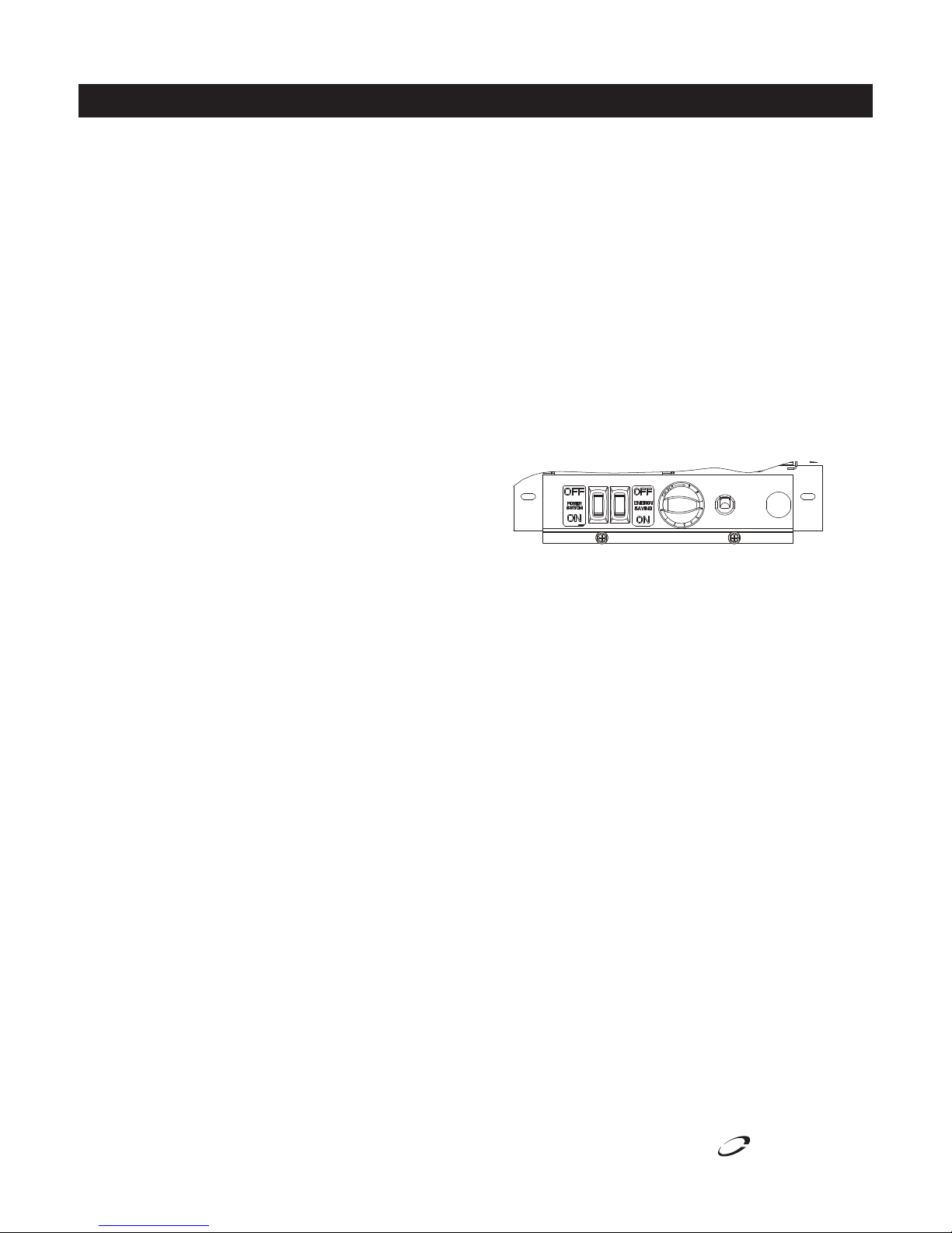
Power Switch
Select units are equipped with a power disconnect switch
located next to the energy saver switch and thermostat control
knob. Switch must be in the “on” position for the unit to
operate. On freezers, if the switch is turned off, then returned
to the on position, the unit will enter a defrost cycle and the
display will read “Def.”
Upon powering unit, there could be up to a 10
minute delay before unit begins to cool.
6
For customer service, call (800) 733-8829, (800) 733-8821, Fax (888) 779-2040, www.delfield.com
™
®

Delfield
Door Reversal Procedures
Standard Edge-Mount Hinge
6000XL Series Service and Installation Manual
Only for Models Ordered With Re-Hinging Option
1. Open door 90˚ and lift door straight up and off hinges.
2. Remove the metal screw covers on each door-side hinge
section by sliding it down and off.
3. Remove two outer screws that mount each hinge to door,
loosen the center screw, rotate hinge 180˚, reinstall outer
screws and retighten center screw.
4. Remove two screws that mount lock on top of door, turn
door up-side-down and remount lock to top of door.
5. Use a 3/16” drill to drill holes in cabinet face frame at the
marked hinge locations on the new hinge side.
6. Remove the cabinet hinge screw covers by gently prying
them out with a small screwdriver.
7. Remove all three screws from each hinge and mount them
to the opposite side of the door opening.
8. Remove the plastic cam from the hinges by pulling straight
up, then rotating the cam 180˚ and pushing back into the
hinge.
9. Remount the door and check for proper closure and gasket
seal. Adjust hinges as needed. Once adjustment is verified,
remove the door, reinstall all hinge screw covers and set the
door back in place.
10. If plugs are needed to plug old screw holes in cabinet face
frame, please contact Delfield Parts Department at (800)
733-8821, extension 12801.
1. Open door 90˚ and lift door straight up and off hinges.
2. Remove the metal screw covers on each door-side hinge
section by sliding it down and off.
3. Remove two outer screws that mount each hinge to door,
loosen the center screw, rotate hinge 180˚, reinstall outer
screws and retighten center screw.
4. Remove two screws that mount lock on top of door, turn
door up-side-down and remount lock to top of door.
5. Pry the plugs out of the hinge mounting holes on the side
opposite the current hinge locations and set them aside.
6. Remove the cabinet hinge screw covers by gently prying
them out with a small screwdriver.
7. Remove all three screws from each hinge and mount them
to the opposite side of the door opening. Press the plugs
removed in step 5 into the screw holes from the original
hinge locations.
8. Remove the plastic cam from the hinges by pulling straight
up, then rotating the cam 180˚ and pushing back into the
hinge.
9. Remount the door and check for proper closure and gasket
seal. Adjust hinges as needed. Once adjustment is verified,
remove the door, reinstall all hinge screw covers and set the
door back in place.
10. If additional plugs are needed due to loss or damage, please
contact Delfield Parts Department at (800) 733-8821, extension 12801.
Leg & Caster Installation
Some cabinets may weigh over 1000 lbs (450 kg).
Use a lifting device capable of supporting the unit
WARNING
To install the legs, or casters refer to Figure 1 and proceed as
follows:
1. Remove unit from skid.
2. Raise unit to access leg/caster mounting bolts on bottom
of unit.
3. Remove the bolts from the cabinet and use them to attach
the legs or casters.
when removing skid or installing legs or casters.
All single-section units require that the swivel
casters be mounted on the front and rigid casters
be mounted on the rear.
™
®
For customer service, call (800) 733-8829, (800) 733-8821, Fax (888) 779-2040, www.delfield.com
Figure 1. Leg or Caster Installation
7
6000XL Series Service and Installation Manual
Delfield
Operation
Electronic Temperature Control
Operation:
The electronic temperature control constantly monitors box
temperature as well as evaporator coil temperature to maintain
consistent product temperatures. The control also sends
temperature readings to the digital temperature display. The
control circuits continually self-check and if an error occurs,
the digital display will switch from temperature read-out to
error read-out, i.e. E 1. Even when an error is displayed, the
refrigeration and controls system should continue to function,
however not at optimal performance. Whenever the display has
an error read-out, Delfield Service should be contacted.
At initial start-up or anytime power is disconnected, then
reconnected to the unit, the control will delay all operations for
a short time (up to 10 minutes.) While in this delay period, the
control initializes the control parameters and confirms that the
temperature sensors and circuits are operational. The digital
temperature display will not display temperature OR errors until
the self-check is complete and the control has switched on the
evaporator fan motor, compressor and condenser fan motor.
Freezer:
The control is located in the control box in the top of the
refrigerator behind the removable louvered panel on the left
side. It is factory set at mid-range to maintain about -3˚F
(-18˚C) box temperature. To adjust for colder temperatures,
turn the knob clockwise. For warmer temperatures, turn the
knob counter-clockwise. Turn the knob fully counter-clockwise
to turn the refrigeration system off. Never turn the knob more
than 1 dial number and always allow 8 hours for temperature
stabilization before making any additional adjustments.
Power Switch
Select units are equipped with a power disconnect switch
located next to the energy saver switch and thermostat control
knob. Switch must be in the “on” position for the unit to
operate. On freezers, if the switch is turned off, then returned to
the on position, the unit will enter a defrost cycle and the display
will read “Def.”
IMPORTANT NOTE REGARDING FREEZERS: After initializing,
the control will immediately enter a DEFROST mode and the
display will read DEF. The compressor and condenser fan as
well as the evaporator fan will remain off until initialization
defrost is complete. This initial defrost cycle may take up to
15 minutes to complete, at which time the freezing cycle will
begin. The display will continue to read DEF for an additional
30 minutes before displaying temperature.
Temperature Alarm:
The alarm will flash “HI” or “LO” 90 minutes after the unit has
reached its alarm temperature point or after any power interruption
if the temperature is above or below the alarm set points.
Refrigerators are factory set at mid-range to maintain about 38ºF
(3ºC) box temperature. The high refrigerator temperature point
is 50°F (10°C). The low refrigerator temperature point is 25°F
(-4°C). Freezers are factory set at mid-range to maintain about 3ºF
(-18ºC) box temperature. The high freezer temperature point is
20°F (-7°C). Freezers do not have a low temperature point.
Refrigerator:
The control is located in the control box in the top of the
refrigerator behind the removable louvered panel on the left
side. It is factory set at mid-range to maintain about 38˚F (3˚C)
box temperature. To adjust for colder temperatures,
turn the knob clockwise. For warmer temperatures, turn the
knob counter-clockwise. Turn the knob fully counter-clockwise
to turn the refrigeration system off. Never turn the knob more
than 1 dial number and always allow 8 hours for temperature
stabilization before making any additional adjustments.
Energy Saver Switch
The energy saver switch is a rocker switch located next to
the thermostat knob that controls the amount of heat applied
to the door perimeter. The normal operating position for this
switch is the ON position, providing the least heat. If excessive
condensation is observed on the door opening, press the
energy saver switch to the OFF position, to increase the amount
of heat (red portion of the rocker switch will be visible).
Refrigeration & Defrost Cycle
Refrigerator:
Whenever the refrigerator is plugged in, and the control
has completed initializing, the digital thermostat will display
box temperature. The temperature control will cycle the
compressor, evaporator fan motor and condenser fan motor to
maintain box temperature at the control setting. See evaporator
fan matrix for more information.
Refrigerator Defrost
The temperature control also monitors the evaporator
temperature and will turn off the compressor and condenser
fan motor when needed to allow accumulated frost on the
evaporator to clear. During this defrost cycle, the digital
temperature display will read dEF. After the defrost cycle is
complete, the temperature control will return to a normal
cooling cycle, but the display will continue to read dEF until the
evaporator returns to normal cooling temperatures (up to 30
minutes).
8
For customer service, call (800) 733-8829, (800) 733-8821, Fax (888) 779-2040, www.delfield.com
™
®
Delfield
Operation, continued
Freezer:
Whenever the freezer is plugged in, and the control has
completed initializing including the initial defrost cycle (also see
Electronic Temperature Control Operation, on this page). The
digital therostat will display box temperature. The temperature
control will cycle the compressor, evaporator fan motor and
condenser fan motor to maintain box temperature at the control
setting. See evaporator fan matrix for more information.
Freezer Automatic Defrost
The control also monitors compressor total running time
and will enter a defrost cycle after total compressor running
time is greater than 4-hours since the last defrost cycle OR
if evaporator coil temperature drops below -30˚F (-34°C)
(indicating excessive frost on the coil).
Freezer Manual Defrost
If a manual defrost is desired, simply unplug the unit for several
seconds, then plug unit back in. This will cause the control to
re-initialize and then enter a defrost cycle.
When the control enters the defrost mode, it switches off the
6000XL Series Service and Installation Manual
evaporator fan motor, compressor and condenser fan motor,
and switches on the defrost heater to warm the evaporator
coil. Thereby melting all frost accumulated during the previous
refrigeration cycle. The digital temperature display will now read
dEF. The control will continue the defrost cycle for a MINIMUM
of 8 minutes and a MAXIMUM of 30 minutes depending on the
amount of frost accumulated on the evaporator coil.
After the defrost cycle is complete, the control returns to a normal
refrigeration cycle, however the evaporator fan motor will not
switch on for 2 minutes AFTER the compressor and condenser
fan motor have begun operating. The digital temperature
display will continue to read dEF until the evaporator has
returned to normal freezing temperatures (up to 30 minutes).
Service Alert
During normal operation the evaporator fan may cycle
and/or pulse independently of the compressor. Consult
the service manual or contact Technical Support at
1-800-733-8829 if you are unsure of the proper function.
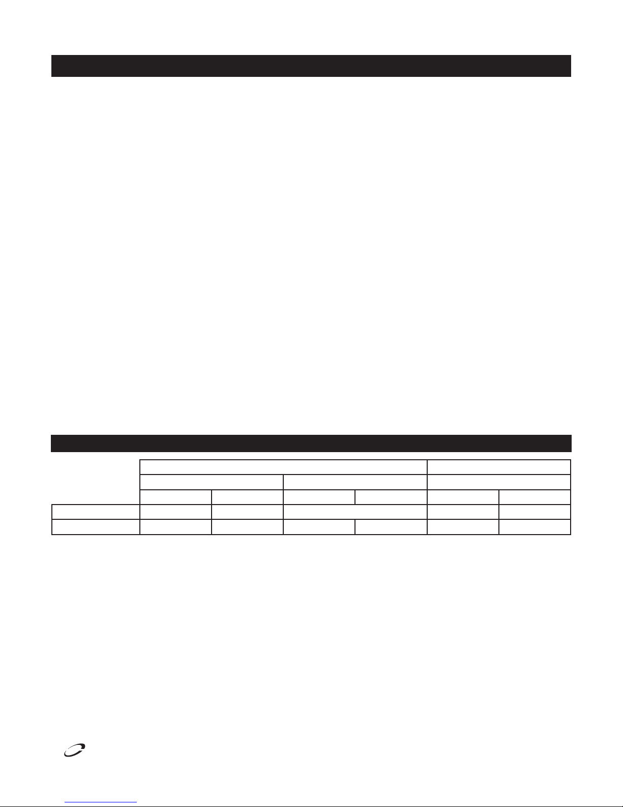
Evaporator Fan Matrix
Cooling Cycle Defrost Cycle
Compressor On Compressor Off Compressor Off
Evap Fan On Evap Fan Off Evap Fan On Evap Fan Off Evap Fan On Evap Fan Off
Refrigerator X Cycles On 3-Min, Off 3-Min X
Freezer X X X
™
®
For customer service, call (800) 733-8829, (800) 733-8821, Fax (888) 779-2040, www.delfield.com
9
 Loading...