

Page 1
Softline
Modline
Conline
Boardline
Avidline
Pixline
Application
MCD Elektronik GmbH
Hoheneichstr. 52
75217 Birkenfeld
Fon +49 (0) 72 31/78 405-0
Fax +49 (0) 72 31/78 405-10
info@mcd-elektronik.de
www.mcd-elektronik.com
HQ : Birkenfeld
Managing CEO: Bruno Hörter
Register Court Mannheim
HRB 505692
Template version: 4.0 / 2017-01-25
V2.3 2017-03-08 MR
Manual
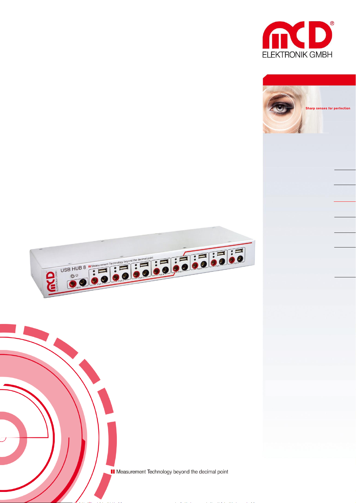
USB hub 2.0, 8-port, switchable
Page 2

Elektronik GmbH USB hub 2.0 8-port Manual
Table of Contents
1. SAFETY INSTRUCTIONS .................................................................................................................................................. 4
2. GENERAL INFORMATION ............................................................................................................................................... 4
3. SCOPE OF DELIVERY ....................................................................................................................................................... 4
4. CONNECTION AND INSTALLATION ................................................................................................................................. 5
4.1. CONNECTING THE DEVICE .................................................................................................................................................... 5
4.2. INSTALLING DRIVERS ........................................................................................................................................................... 6
4.3. INSTALLING TOOLMONITOR ................................................................................................................................................. 6
5. INTRODUCTION ............................................................................................................................................................. 7
5.1. FEATURES......................................................................................................................................................................... 7
5.2. CONSTRUCTION ................................................................................................................................................................. 8
5.3. DISPLAY ........................................................................................................................................................................... 8
5.4. BUTTON ........................................................................................................................................................................... 8
6. FUNCTION OF THE USB PORTS ....................................................................................................................................... 9
6.1. OPERATING MODES ............................................................................................................................................................ 9
6.2. CONNECTION DETECTION .................................................................................................................................................... 9
6.3. CURRENT MEASUREMENT .................................................................................................................................................. 10
6.4. CURRENT LIMITATION ....................................................................................................................................................... 10
7. FUNCTION OF THE RELAY MULTIPLEXER ...................................................................................................................... 11
8. FUNCTION OF THE USB HUB 2.0 8-PORT ...................................................................................................................... 12
8.1. BEHAVIOR WHEN POWER IS APPLIED .................................................................................................................................... 12
8.2. BEHAVIOR IN READY MODE ................................................................................................................................................ 12
8.3. BEHAVIOR AFTER READY MODE ........................................................................................................................................... 12
8.4. BUTTON LOCK ................................................................................................................................................................. 12
8.5. SAVING THE CONFIGURATION ............................................................................................................................................. 12
8.6. RECOGNITION NUMBER ..................................................................................................................................................... 12
8.7. RESETTING ..................................................................................................................................................................... 13
9. SOFTWARE MANUAL ................................................................................................................................................... 14
9.1. PROGRAMMING INTERFACE ............................................................................................................................................... 14
9.2. PROGRAM SETTINGS ......................................................................................................................................................... 15
9.3. USB HUB CONFIGURATION ................................................................................................................................................ 16
9.4. USB HUB COMMAND LINE ................................................................................................................................................. 17
Seite 2 von 21
Page 3

Elektronik GmbH USB hub 2.0 8-port Manual
10. TECHNICAL DATA ..................................................................................................................................................... 19
11. INTERFACE DESCRIPTION ......................................................................................................................................... 20
Seite 3 von 21
Page 4

Elektronik GmbH USB hub 2.0 8-port Manual
1. Safety instructions
The USB hub 2.0 8-port is intended for use indoors. It may not be exposed to moisture. If the device is brought
from a cold environment into a warm one, it must be allowed to stand for at least one hour without the power
cord and other cables connected until any condensation moisture has dried.
The device has no parts that can be replaced by the user. Any repair must be carried out by a trained technician.
Before opening the housing, disconnect the power cord and wait for about a minute.
2. General information
This USB hub has eight USB 2.0 downstream ports that can be turned on and off individually via USB. When they
are turned off, the power supply (+5V) and the data lines are isolated by semiconductor switches. Control is
provided by the USB hub Toolmonitor (PC software). Whether ports are active after the device is turned on, and
which ports, can be configured and stored.
Each USB port can be configured as a standard port (SDP), charging-capable connection (CDP), or a charger
connection (DCP) and provides the connected device with up to 2.5A.
In addition to the USB ports, the USB hub also has an 8-channel relay multiplexer that can be used to turn a
centrally connected voltage (at most 48V) on each port individually on and off independently from one another,
for example for supplying a device with a voltage other than 5V. The connection uses a 4mm banana plug.
Whether and which ports should be activate after the hub is turned on (for example to have access to the mouse
or keyboard) can be stored in non-volatile storage.
A switch on the device can be used to turn off all ports temporarily or to restore the previous switching state of
all ports.
A number that can be stored in the device can be used to distinguish between multiple USB hub 2.0 8-port units
on a PC.
External software can be used to control the USB hub Toolmonitor completely remotely. COM/DCOM or a .Net
assembly can be used as the interface. This allows the USB hub Toolmonitor to be integrated into many different
applications (MCD TestManager CE, LabView ®, Microsoft Visual Studio ® (C#, C++, Visual Basic), Microsoft
Office ® (for example Excel ®), Open Office ®). It is also possible to use the USB hub under Linux.
Order number: # 121142
3. Scope of delivery
1x USB hub 2.0 8-Port
1x USB storage card with installation software
1x USB 3.0 connection cable 2m
1x power cord 1.8m
Seite 4 von 21
Page 5

Elektronik GmbH USB hub 2.0 8-port Manual
USB cable /
type AB
90 – 132 VAC
or
187 – 264 VAC
47 – 63Hz
4. Connection and installation
4.1. Connecting the device
The USB hub 2.0 8-port can optionally be operated on 110V or 230V power grids. The power switch on the back
turns the device on and the button on the front left lights up. When delivered, all relays turn on and all USB ports
are off. This is indicated by the different signal LEDs. The power-on behavior can be changed later.
Front view of the USB hub:
Connecting the USB hub to your PC:
/
Seite 5 von 21
Page 6
Elektronik GmbH USB hub 2.0 8-port Manual
4.2. Installing drivers
Connect the USB 2.0 HUB 8 to a free USB port and turn it on with the switch on the back. The actual USB hub is
detected automatically by Windows and appropriate drivers are installed. Additional drivers are required for the
control components. The following options are available:
1) If the PC has access to the Internet, starting with Windows 7 ® the driver is automatically loaded and
installed by Windows Update.
2) Alternatively, the driver can be loaded and installed from http://www.ftdichip.com/Drivers/VCP.htm.
For a simple installation, please click "setup executable".
3) If "MCD USBHub8Monitor" is included, after it is installed the driver can be found and installed in the "USB
Driver" directory of its installation directory.
By default, the installation path is:
<Drive name>:\MCD Elektronik GmbH\MCD USBHub8Monitor\USB Driver
4.3. Installing Toolmonitor
The USB 2.0 HUB 8 can be completely controlled via text commands (see Chapter 11 on p. 20). Optionally, the
USBHub8Monitor can be installed as a graphical user interface and as an interface for other applications. To do
this, start the USBHub8Install installer (EXE or MSI file) and follow the instructions in the installation dialog. After
installation, the Toolmonitor can be started from the Start menu.
Under Setup Register COM Server, the Toolmonitor can be registered so that it can be controlled from other
applications.
Seite 6 von 21
Page 7

Elektronik GmbH USB hub 2.0 8-port Manual
5. Introduction
5.1. Features
Relay multiplexer
8 channels, individually switchable
Up to 48VDC / 2A (max. 30W) per channel under resistive load
Display for channel on or off
USB downstream ports
8 ports, individually switchable with up to 2.5A per port.
Each port is protected by a resettable overload breaker.
Current limitation adjustable
Connected devices are protected from excess current by the adjusted shutoff limit.
Adjustable charger emulation for many mobile devices (such as CDP, DCP, etc.).
An automatic mode tries different profiles.
Detection of whether a device has been connected to a port.
Also detects when devices are connected that are not USB devices
(such as USB fans, USB reading lights, etc.).
Current measurement for every port (resolution about 10mA)
Detection of defects (e.g. current consumption too high / too low).
Measurement of the current consumption of connected devices.
Display for port/channel: on / off / excess current / charge / charge complete / no device connected
Mode always visible from outside.
Host connection
Controlled from USB hub connection
Hub functionality and control of the hub with just one cable.
Button
Indicates operating / ready mode on.
Turns off previously determined or all USB ports and relay channels.
Can provide the function of an emergency stop.
If necessary, turns only certain devices off, while for example the mouse and keyboard remain
active.
Other
Operating state on power-on (e.g. active USB ports and relay channels) can be specified and stored.
With appropriate configuration, can also act as a USB charger without a USB host.
Defined operating state on power-on appropriate to any application.
User-defined labeling of the hub to distinguish it from other USB hubs on the controlling host.
Seite 7 von 21
Page 8

Elektronik GmbH USB hub 2.0 8-port Manual
Relay turned off
Relay turned on
USB port turned off
USB port turned on, but no device connected
USB port turned on
Device turned off
Ready mode
Normal mode
Hub Hub
Port 1 - 4Port 5 - 8
USB in
Mux 1 - 8
Control
5.2. Construction
5.3. Display
Indicators of USB-Ports configured as charging ports are dimmed when the charging has finished.
5.4. Button
Seite 8 von 21
Page 9

Elektronik GmbH USB hub 2.0 8-port Manual
6. Function of the USB ports
6.1. Operating modes
The USB hub provides eight high-speed-capable USB 2.0 ports. Each port can be configured to one of four
modes. These four modes are:
1. Standard port (SDP):
If the maximum current is exceeded, the port shuts off.
2. Charge-capable port (CDP):
Like a standard port, but it announces itself to the connected USB device as a charge-capable USB port
according to the USB battery charging specification V1.2 (USB-IF BC1.2 CDP).
The current is limited to the maximum possible value.
3. Dedicated charging port (DCP BC1.2)
The port announces itself to the connected USB device as a dedicated charging port according to the
USB battery charging specification V1.2 (USB-IF BC1.2 DCP).
The current is limited to the maximum possible value.
In this mode, no USB communication is possible with the connected device!
4. Dedicated charging port (DCP)
The port attempts to negotiate a charging protocol with the connected device. To do this, it tries
different variants one after the other, including BC1.2 DCP, YD/T-1591 (2009) and variants compatible
with many portable devices from Apple ® and RIM ®.
The current is limited to the maximum possible value.
In this mode, no USB communication is possible with the connected device!
DCP connections can also be active without a host connected.
Due to the many charging schemes – some of which are manufacturer-specific – there is no guarantee
that battery charging will succeed with a particular mobile device and that no damage can result!
6.2. Connection detection
The USB ports have a function to detect when a USB device is connected. This also works for connected
devices that only use the power from the connection (e.g. USB fans or reading lights). Connection detection
can be disabled individually for each port if the small test current should lead to unexpected problems.
In CDP mode, it may be that the connection detects such a device, but does not detect when it is
disconnected. This has no effect on the other functions of the USB hub, however. Connecting a normal
USB device or turning the port on and off will reset connection detection again.
Seite 9 von 21
Page 10

Elektronik GmbH USB hub 2.0 8-port Manual
Mode
Current limitation
Standard port (SDP)
900mA – 1000mA
Charge-capable data connection (CDP)
1500mA – 1800mA
BC 1.2 dedicated charging port (DCP)
2000mA – 2500mA
Charger emulation
2000mA – 2500mA
6.3. Current measurement
Each USB port has a mechanism to measure the current, with a resolution of about 10mA. This permits the
actual current consumption of the connected device to be measured and monitored. This applies to both
operating currents of USB devices and non-USB devices as well as charging currents.
6.4. Current limitation
The switching threshold for current limitation can be configured individually for each USB port in steps of
500mA to up 2500mA. Current limitation is in principle configurable regardless of use, but the following
limits are recommended:
Most USB connectors are specified at 1.5A to 1.9A. So in general, a current limitation of no more than
2000mA should be configured.
Seite 10 von 21
Page 11

Elektronik GmbH USB hub 2.0 8-port Manual
IN
OUT 1 OUT 8
7. Function of the relay multiplexer
The relay multiplexer makes it possible to emit an externally powered voltage on up to eight outputs. This
permits, for example, USB devices to be powered that cannot be operated with operating voltage via USB.
The multiplexers can be switched independently of the USB ports. The connection uses a
4mm banana plug.
The multiplexers are not fused. They can be damaged in case of overload.
Seite 11 von 21
Page 12

Elektronik GmbH USB hub 2.0 8-port Manual
8. Function of the USB hub 2.0 8-port
8.1. Behavior when power is applied
It can be determined whether the USB goes into normal mode after power is turned on, or initially into
ready mode.
If normal mode is active, then the ports and multiplexers are turned on as configured in advance. If the hub
has not yet been enumerated by the host, all communications ports (SDP and CDP) remain off until
enumeration is complete and will only then be turned on.
In ready mode, the hub acts as though it had been placed in ready mode immediately after being turned on
(see next section). Ports for which no exceptions are defined are not turned on.
8.2. Behavior in ready mode
The button on the front panel can be used to switch the USB hub from normal mode into ready mode and
back. In ready mode, all ports and multiplexers are normally turned off; however, exceptions can be defined
for devices that should not be turned off (e.g. for the mouse/keyboard or for charging ports). Ports or
multiplexers that are already switched off, however, are not turned back on in ready mode, even if an
exception has been defined for them. In ready mode, the hub rejects any command for configuration or
setting of ports or multiplexers from the PC. Read accesses continue to work. This prevents devices turned
off manually from being turned back on by the PC unintentionally.
8.3. Behavior after ready mode
If the USB hub returns to normal mode after ready mode, it either restores the state of the ports
immediately before ready mode or switches the ports to the same state as before the USB hub was turned
on. Which of these two behavioral patterns is followed can be configured.
8.4. Button lock
The button can be locked against unintentional actuation. If this function is saved, the USB will always go
into normal mode after being turned on.
8.5. Saving the configuration
All settings can also be written to the hub for storage. In this case, the currently active settings are not
affected. Saved settings will be restored the next time the hub is turned on.
The storage cells for configuration are subject to a certain amount of wear (> 100,000 write cycles). The
storage commands should therefore not be executed within a program loop or the like.
The USB ports always change mode only after the device is turned off and on again.
8.6. Recognition number
The USB hub can permanently store a number (00 to FF hexadecimal, or 0 to 255 decimal) that can be
queried later. This helps distinguish between multiple hubs on a PC. Otherwise, this number has no function.
Seite 12 von 21
Page 13

Elektronik GmbH USB hub 2.0 8-port Manual
8.7. Resetting
Pushing the button on the front panel for about 10 seconds resets the USB hub to factory settings. The hub
then restarts. The ports and multiplexers will be switched accordingly. This must be followed by the
corresponding command. If the button lock is active, this function is not possible. The factory settings
include:
Normal mode after power on
No exceptions for ready mode
After ready mode, restore the state from before ready mode
All USB ports are standard ports (SDP)
Current limitation of all ports is 2.5A
Connection detection for USB devices is enabled
The button is unlocked.
All USB ports are off after the USB hub is turned on
All relay multiplexers are on after the USB hub is turned on
The recognition number is not changed
All USB ports are turned off by a reset. Disconnect all connected storage media from the operating
system beforehand.
The relay multiplexers will all be turned on. Disconnect any connections for which this is not desired.
Seite 13 von 21
Page 14

Elektronik GmbH USB hub 2.0 8-port Manual
Switching state of USB ports
Port turned off
Port turned on; no connected device detected
Port turned on; connected device detected or detection function turned off
Port is off although it should be turned on
Possible cause:
Excess current shutoff
Connected device feeds current back into the USB hub.
Switching state of relay multiplexer outputs
Output turned off
Output turned on
9. Software Manual
9.1. Programming interface
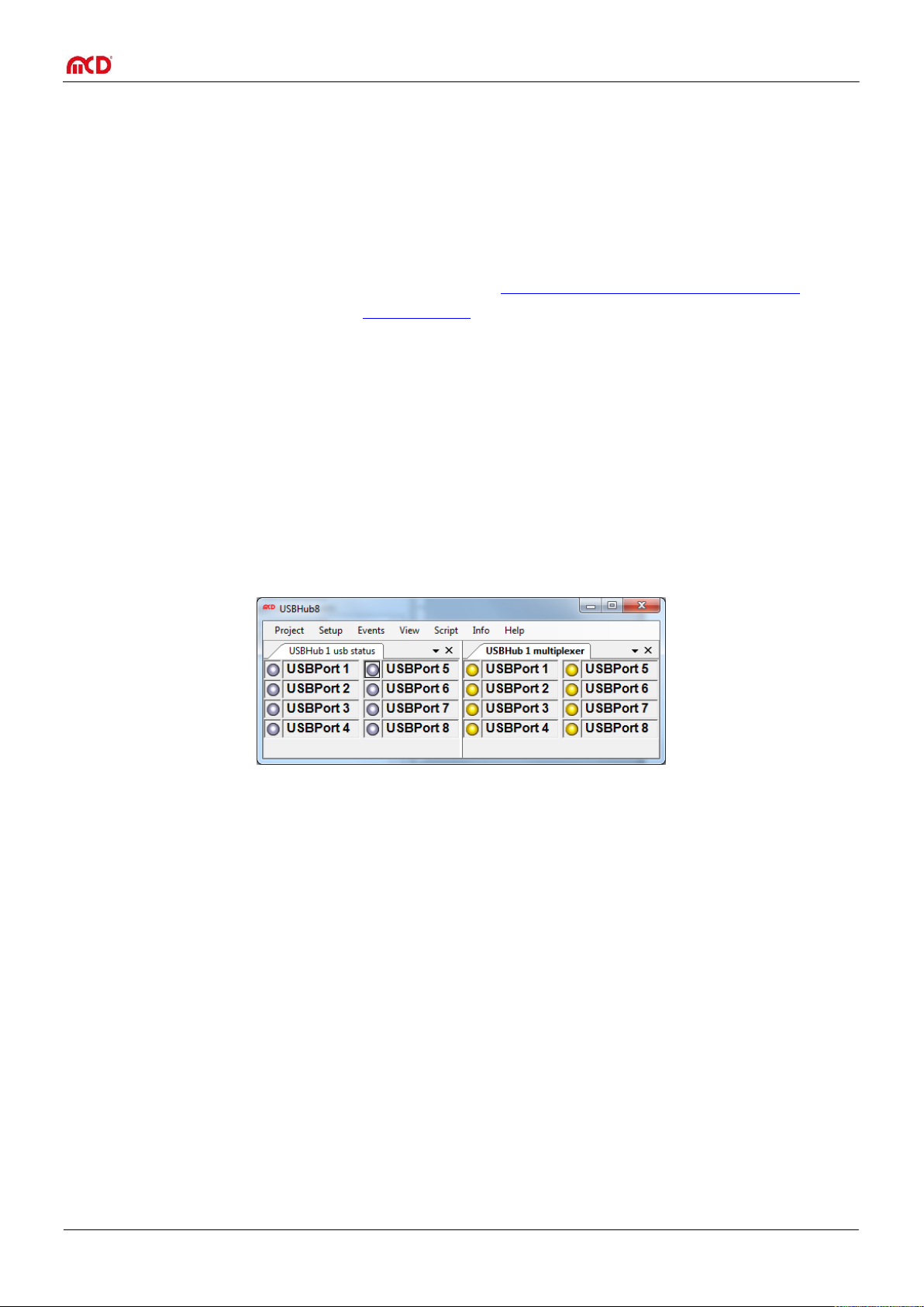
After the Toolmonitor starts, the interface looks like this:
The switching state of each port and multiplexer output is shown.
The supply or charging current out of the USB ports can also be displayed.
Seite 14 von 21
Page 15

Elektronik GmbH USB hub 2.0 8-port Manual
A name can be given to the USB hub here.
If multiple USB hubs are connected, here you can select which of the names specified above
should be controlled.
These two checkboxes should always be set.
Determines the number of lines on which USB hubs are shown. If this is zero, it is automatically
set depending on the size of the window.
Here, USB ports can be given names, e.g. the names of the connected devices. The same names
are used for associated relay multiplexer outputs.
In "USBHub6", the number of USB hubs to be controlled can be configured. New USB hubs are
given the name "USBHub" with an incrementing number.
3 4 5
1
4 5 3
1
2
2
6
6
9.2. Program settings
Basic settings are configured under Setup –> Options. The default settings are sufficient for an initial
commissioning.
Seite 15 von 21
Page 16

Elektronik GmbH USB hub 2.0 8-port Manual
On power up, the corresponding USB port is switched on when the box is checked.
On power up, the corresponding relays multiplexer output is switched on when the box is checked.
Turns device detection on. In DCP mode and charger emulation, device detection is necessary for
correct functioning. Devices that consume less than 1mA from the USB port are frequently not
detected and the port is then not released. For this case, device detection can be turned off.
Places an exception for the corresponding USB port Such a port will not be influenced by standby.
The same for the relay multiplexer outputs.
Places the corresponding port into SDP, CDP, DCP, or charger emulation mode.
Sets the current limitation per port.
If this option is active then the USB ports and relay multiplexer output are switched as configured
when power is switched on. Otherwise the behavior is like the standby button was pushed at power
on and only ports and outputs with exceptions applied can switch on.
1 2 3 4 5 6 1 2 3
4
5
8
11
12 7 10
10
6
7
8
The USB hub can be configured using the configuration dialog. This is located in the standard settings under
View –> USBHub 1 –> USBHub 1 config:
9.3. USB hub configuration
Seite 16 von 21
Page 17

Elektronik GmbH USB hub 2.0 8-port Manual
With this option the USB hub restores the ports and multiplexer outputs after standby as they were
before. Otherwise the power-up configuration is restored.
Activating this option disables the button on the front. The hub will always switch on normally after
power-up so the function of item 8 does not apply
Reads out the configuration currently stored.
Saves the configuration set up in the dialog, but does not apply it. This configuration is restored by
the USB hub after uninterrupted power supply is restored.
9
10
11
12
1
2
3 4 5 6 7
9.4. USB hub command line
Under View –> USBHub 1 –> USBHub 1 communication, a window can be opened for direct communication
with the controller in the USB hub:
Seite 17 von 21
Page 18

Elektronik GmbH USB hub 2.0 8-port Manual
Here, the data traffic between the Toolmonitor and the control unit of the USB hub can be viewed
directly.
A list of commands that can be extended and changed.
Commands can be sent directly to the USB hub here (see chapter 11) to be able to include the
command in the list, it must be assigned a name. The comment is optional.
When this button is pressed, the command is executed.
Opens or closes the control interface to the USB hub. When the interface is closed, the hub is
released and other applications can access the USB hub.
These buttons can be used to add the command entered on the left into the list, or edit the
command.
These buttons sort the command currently selected in the list up or down.
1 2 3
4
5
6
7
Seite 18 von 21
Page 19

Elektronik GmbH USB hub 2.0 8-port Manual
Electrical characteristics
Operating voltage
90 – 132 / 187 – 264 VAC
47 – 63Hz
When changing the input voltage, turn
off the device first!
Connection power
max. 100W
including power supply to connected
devices via USB
Output current
limitation
on USB ports (5V)
Configurable in steps:
from500mA / port
to 2500mA / port
450mA – 500mA
2250mA – 2500mA
Connection values for
input voltage
max. 48V / 10A
Connection values for
output voltage
max. 48V / 2A per output
maximum switched power 30W
Total current on all outputs
may not exceed 10A
Mechanical characteristics
Dimensions (H x W x D)
44mm x 350mm x 115mm
without connectors or supporting feet
Connections
Cold-device plug
Power supply (back)
(1) USB-B
Upstream to host (back)
(8) USB-A
Downstream to USB devices
Port 1 is at the top left, Port 8 at the
bottom right (front view)
(1x2) banana plugs 4mm
Power supply (front)
(8x2) banana plugs 4mm
Switched power output (front)
Other characteristics
USB version
USB 2.0
requires a USB 2.0 host
Control
via USB
Display
(8) green LEDs
for active USB ports
(8) yellow LEDs
for active voltage outputs
Illuminated button
Green = normal mode
Red = ready mode
Control interface
Virtual serial port via USB
19200 baud
1 start bit
2 stop bits
No handshake
Ambient temperature
0 – 40°C (32 °F – 104 °F)
Weight w/o accessories
1.4kg (3 lb)
10. Technical data
Seite 19 von 21
Page 20

Elektronik GmbH USB hub 2.0 8-port Manual
Comm
and
Parameter
Response
value
Comment
with prefix
"D"
Switching
P
00 - FF
ok
Bit mask of all eight ports in hexadecimal. A set bit
corresponds to an active USB port. Thus if the lowest bit
is set, then Port 1 is active; if the highest bit is set, Port 8
is active.
X
M
00 - FF
ok
Bit mask of all eight relay multiplexers in hexadecimal.
The parameters are evaluated as described above.
X
R P 00 – FF
Read the switching state (set state) of the USB port.
X R PP
00 – FF
Read the switching state (actual state) of the USB port.
R M
00 – FF
Read the switching state of the relay multiplexer.
X
Port functionality
A 00 – FF
ok
Connection detection on
X R A
00 – FF
Read active connection detection
X R AA
00 – FF
Read the detection of connected devices.
C
0 – 7
0 – 3
ok
USB port to be configured
Mode:
0 = Standard port (SDP)
1 = USB-IF BC1.2 charge-capable port (CDP)
2 = Multiprotocol dedicated charging port (DCP)
3 = USB-IF BC1.2 dedicated charging port (DCP)
X
R
C
0 – 7
0 – 3
Read the mode (0 – 3; see above)
Port to be read
X
L
0 – 7
0 – 7
ok
USB port to be configured
Current limitation (see table below)
X
R
L
0 – 7
0 – 7
Read current limitation (see table below)
Port to be read
X
R
I
0 – 7
0000 – 61A8
Read actual current in 0.1mA steps
Port to be read
11. Interface description
The command line interface uses simple ASCII strings. Recognized valid commands are acknowledged with the
string "ok" if the command is a configuration command. For a read command, the corresponding data is sent. An
unrecognized command is answered with "???". In ready mode, all configuration commands are answered with
"off". A prefix "D" changes no current settings, but rather specifies a write or read access to the non-volatile
memory from which the configuration will be taken when the USB hub is turned on. All strings are terminated
with a CR (ASCII 13).
Seite 20 von 21
Page 21

Elektronik GmbH USB hub 2.0 8-port Manual
Comm
and
Parameter
Response
value
Comment
with prefix
"D"
Behavior when power is applied
SS
S | R
ok
Device state after power applied
S = hub goes into normal mode after power applied
R = hub goes into ready mode after power applied
Only with prefix "D"!
X
R
SS
S | R
Read device state after power applied
X
Behavior in standby mode
E
00 – FF
ok
Defines exceptions for which ports will not be turned off
even in standby mode. However, if they were off before
standby, they remain off. The parameters are evaluated
as described above under "P".
X
F
00 – FF
ok
Defines exceptions for which relay multiplexers will not
be turned off even in standby mode. This function works
just like the ports.
X
R E 00 – FF
Read exceptions for the USB ports
X R F
00 – FF
Read exceptions for the relay multiplexers
X
Special
ST
S | R
ok
Button locked (S) or released (R)
X
SI
S | R
ok
Port setting after ready mode:
S = as before ready mode
R = as after power applied
X N 00 - FF
ok
Store an ID number for later identification; only with
prefix "D"!
X
R
ST
S | R
Read button lock status
X R SI
S | R
Read port settings after ready mode
X R N
00 – FF
Read the ID for identification
X R V
String
Version of the firmware
Parameter
Nominal value of current
limitation
Minimum
Typical
Maximum
0
500mA
450mA
467mA
500mA 1 900mA
810mA
839mA
900mA 2 1000mA
900mA
932mA
1000mA 3 1200mA
1080mA
1112mA
1200mA 4 1500mA
1350mA
1385mA
1500mA 5 1800mA
1620mA
1892mA
1800mA
6
2000mA
1800mA
1892mA
2000mA
7
2500mA
2250mA
2355mA
2500mA
Table: Parameters for current limitation
Seite 21 von 21
 Loading...