

McDaniel Metals PGED101, PGED102 Installation Manual
PGED101/102 INSTALLATION AND OPERATION GUIDE
to cool the space. (Go to step 5.)
E
Outdoor air dampers open to minimum position and the 4.
compressor engages to provide mechanical cooling.
When the thermostat is satisfi ed the outside air dampers 5.
return to a closed position.
PGED101/102
B
D
C
B
A
20 16.25 16 23.5 12.5 45.75
E
C
A
F
F
D
ECONOMIZER 101
Economizers are designed to provide “free” air conditioning
when outside conditions are appropriate. When the outside air
is cool and dry enough, the economizer automatically opens to
introduce the cool air to the interior space, thereby eliminating
the need to run the air conditioning compressor.
If the outside air becomes too warm or humid, the economizer
automatically closes the fresh air damper and the compressor
engages to begin cooling the space mechanically.
If a two stage thermostat is used it is possible to use a
combination of economizer and mechanical cooling to condition
the space.
The economizer can also be set to allow a minimum amount of
fresh air to enter the space when the equipment’s indoor blower
is operating.
Economizers are valuable tools to enhance indoor air
quality, save energy and prolong the life of the air conditioning
equipment.
SEQUENCE OF OPERATION
This sequence assumes employment of a single enthalpy
economizer using a two stage thermostat.
A call for cooling comes from room thermostat.1.
The enthalpy sensor determines if the atmospheric condi-2.
tions are conducive for using outside air for cooling. If YES,
go to step 3. If NO, or if outdoor air temperature rises above
enthalpy set point, go to step 4.
The outside air dampers open and modulate to maintain a 3.
mixed air temperature (outside air + indoor air) of 53 degrees
F. If the outdoor air is insuffi cient to satisfy the thermostat
alone and a second stage of cooling is required, the compressor starts and works in conjunction with the economizer
Figure 1
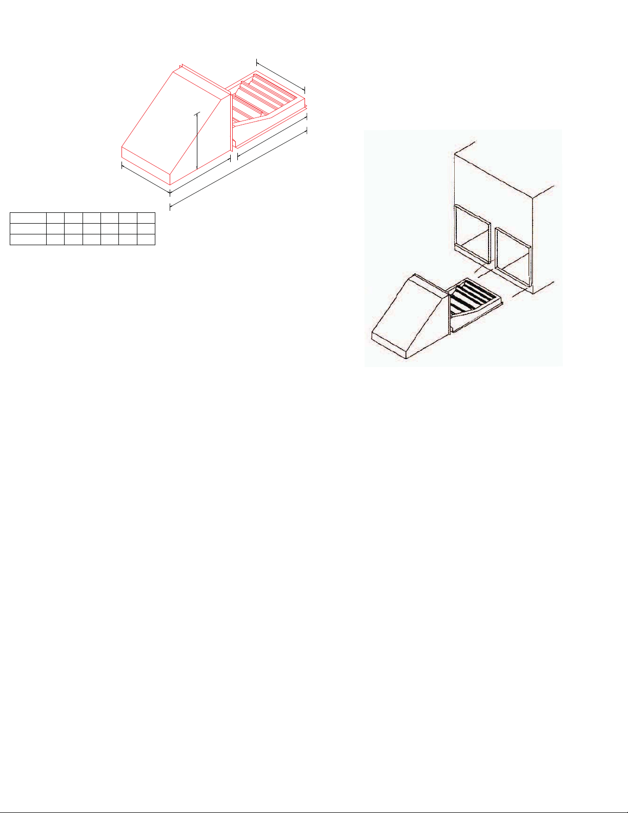
INSTALLATION
Open carton and inspect contents for shortages and damage.1.
Remove large blower access panel from package unit. 2.
Remove the horizontal duct opening cover.3.
Remove the downfl ow return air panel inside of the unit.4.
Slide the damper/hood assembly into the horizontal opening 5.
until the return air dampers are above the downfl ow return air
opening and the fresh air hood is against the side of the unit.
Attach the hood to the side of the unit using sheet metal 6.
screws.
NOTE: Ensure that the wires do not interfere with either the
fresh air or return air damper operation. The wires should not be
pinched between the fresh air hood and the unit or the return air
dampers and the base pan.
Feed wires through to the control section of the unit and hard 7.
wire per wiring diagram attached.
Seal connection between the fresh air hood and unit until 8.
water tight.
Determine the proper enthalpy setting using enclosed control 9.
documentation if it is different from the factory ‘D’ setting.
Determine the minimum position setting using the minimum 10.
set point equation on page two.
Replace the blower access panel.11.

MINIMUM SET POINT EQUATION
CONTENTS
(To X OA) + (Tr X RA) = Tm
To = Outdoor air temperature
OA= Percent of outdoor air
Tr = Return air temperature
RA= Percent of return air
Tm= Resulting mixed air temperature
Example:
Fresh air required is 10% outdoor air.
Outdoor air temperature is 60 degrees F.
Return air temperature is 75 degrees F.
(0.1 X 60) + (0.9 X 75) =
6.0 + 67.5 = 73.5
Mixed air temperature will be 73.5 degrees F when
the OA is 60 degrees F and the RA is 75 degrees F
with 10% outdoor air.
1 Damper rack w/ economizer controls
1 Installation guide
1 Honeywell control literature
ACCESSORIES / CAPABILITIES
Dual Enthalpy - Requires an additional C7400 enthalpy
control installed in the return air duct.
Demand Control Ventilation - Requires a CO2 sensor.
Remote Minimum Positioner - For applications requiring
minimum position adjustments inside the conditioned space.
Important Notes
Please see enclosed brochure for Honeywell
component trouble shooting instructions.
Controller is factory set for power exhaust to
engage when the dampers are 70% open.
A two stage thermostat is recommended with this
accessory.
The fresh air requires a 16 X 20 X 2 fi lter.
The return air requires a 14 X 25 X 2 fi lter.
 Loading...