

McDaniel Metals DNECONGS90120 Installation Manual
DNECONGS90120 INSTALLATION AND OPERATION GUIDE
to cool the space. (Go to step 5.)
Outdoor air dampers open to minimum position and the 4.
compressor engages to provide mechanical cooling.
When the thermostat is satisfi ed the outside air dampers 5.
return to a closed position.
ECONOMIZER 101
Economizers are designed to provide “free” air conditioning
when outside conditions are appropriate. When the outside air
is cool and dry enough, the economizer automatically opens to
introduce the cool air to the interior space, thereby eliminating
the need to run the air conditioning compressor.
If the outside air becomes too warm or humid, the economizer
automatically closes the fresh air damper and the compressor
engages to begin cooling the space mechanically.
If a two stage thermostat is used it is possible to use a
combination of economizer and mechanical cooling to condition
the space.
The economizer can also be set to allow a minimum amount of
fresh air to enter the space when the equipment’s indoor blower
is operating.
Economizers are valuable tools to enhance indoor air
quality, save energy and prolong the life of the air conditioning
equipment.
SEQUENCE OF OPERATION
This sequence assumes employment of a single enthalpy
economizer using a two stage thermostat.
A call for cooling comes from room thermostat.1.
The enthalpy sensor determines if the atmospheric condi-2.
tions are conducive for using outside air for cooling. If YES,
go to step 3. If NO, or if outdoor air temperature rises above
enthalpy set point, go to step 4.
The outside air dampers open and modulate to maintain a 3.
mixed air temperature (outside air + indoor air) of 53 degrees
F. If the outdoor air is insuffi cient to satisfy the thermostat
alone and a second stage of cooling is required, the fi rst
stage compressor starts and works in conjunction with the
economizer
Figure 1
INSTALLATION
Open carton and inspect contents for shortages and damage.1.
Remove large evaporator access panel from package unit 2.
and discard. Remove the smaller fi lter access panel and the
horizontal return air panel.
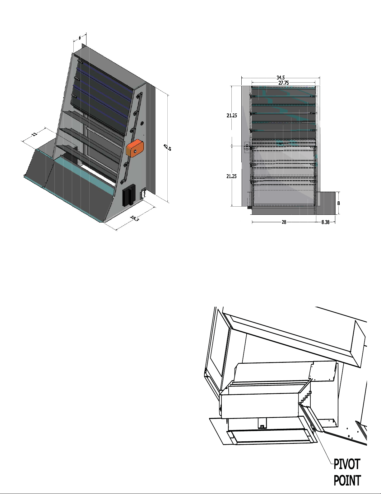
Slide the damper rack into the large opening and rotate the 3.
damper in position around the pivot point in Figure 2.
Slide the dampers in the opening until the front fl anges are 4.
fl ush with the corner post and divider post between the fi lter
access panel and the evaporator access panel.
Evaporator
Downfl ow
R/A Opening
Top of Damper Rack
Top View
Figure 2

From the horizontal return opening, plug 9-pin economizer 5.
plug into matching 9-pin plug in the unit.
CONTENTS
NOTE: Ensure neither the wire nor the plugs interfere with the
movement of the dampers during operation.
Install the new access panel on the unit.6.
Secure access panel to the unit with the screws provided.7.
Assemble the barometric relief hood and the fresh air hoods 8.
with the screws provided. Be sure to install the mist eliminators before installing the front fi lter access piece. (See
FIGURE 3)
Install gasket material on the economizer panel outside of the 9.
hood openings using the hood mounting holes as a guide.
Refer to psychrometric chart included with controller check 10.
out literature to determine the A, B, C, or D setting for the
controller. The factory setting is the D position.
Use the minimum set point equation (see below) to determine 11.
the minimum position setting on the controller. The factory
setting is closed or full CCW.
Install barometric relief hood with screws provided through 12.
access panel and economizer.
Install the fresh air hood with the screws provided through the 13.
access panel and economizer.
Run a bead of silicone or other approved sealant along the 14.
hood fl anges to ensure a watertight seal.
Replace fi lter access panel and the horizontal return panel on 15.
the unit.
1 Damper rack w/ economizer controls
2 Fresh air hood sides
1 Fresh air hood top
1 Fresh air hood fi lter access
2 Barometric relief hood sides
1 Barometric relief hood top
1 Barometric relief hood fi lter access
2 Mist eliminator
1 Access Panel
1 Screw package and control jumpers
1 Installation Instructions and Compo-
nent Manual
1 T1070 Gasket Material
ACCESSORIES / CAPABILITIES
Dual Enthalpy - Requires an additional C7400 enthalpy
control installed in the return air duct.
MINIMUM SET POINT EQUATION
(To X OA) + (Tr X RA) = Tm
To = Outdoor air temperature
OA= Percent of outdoor air
Tr = Return air temperature
RA= Percent of return air
Tm= Resulting mixed air temperature
Example:
Fresh air required is 10% outdoor air.
Outdoor air temperature is 60 degrees F.
Return air temperature is 75 degrees F.
(0.1 X 60) + (0.9 X 75) =
6.0 + 67.5 = 73.5
Mixed air temperature will be 73.5 degrees F when
the OA is 60 degrees F and the RA is 75 degrees F
with 10% outdoor air.
Demand Control Ventilation - Requires a CO2 sensor.
Power Exhaust - DNPE3672 power exhaust used in
applications where barometric relief is not suffi cient.
Remote Minimum Positioner - For applications requiring
minimum position adjustments inside the conditioned
space.
Important Notes
If Power Exhaust or Demand Control Ventilation
is not utilized ensure that the DCV Set and DCV
Max pots are full counterclockwise.
Please see enclosed brochure for Honeywell
component trouble shooting instructions.
Controller is factory set for power exhaust to engage when the dampers are 70% open.
The fresh air mist eliminator should be fl ushed
periodically with warm soapy water.
A two stage thermostat is recommended with this
accessory.
 Loading...