

McDaniel Metals DDNECNJ180240 Installation Manual

281-987-8400 • 281-987-9494 (fax)
1318 Buschong, Houston, TX 77039
www.mcdanielmetals.com
ECONOMIZER 101
Economizers are designed to provide “free” air condioning
when outside condions are appropriate. When the outside air
is cool and dry enough, the economizer automacally opens to
introduce the cool air to the interior space, thereby eliminang
the need to run the air condioning compressor.
If the outside air becomes too warm or humid, the economiz-
er automacally closes the fresh air damper and the compressor
engages to begin cooling the space mechanically.
If a two stage thermostat is used it is possible to use a combi-
naon of economizer and mechanical cooling to condion the
space.
The economizer can also be set to allow a minimum amount
of fresh air to enter the space when the equipment’s indoor
blower is operang.
Economizers are valuable tools to enhance indoor air qual-
ity, save energy and prolong the life of the air condioning
equipment.
DDNECNJ180240
DOWNFLOW JADE ECONOMIZER
FOR DAIKIN DCG180-240 AND
DCC180-240
to cool the space. (Go to step 5.)
4. Outdoor air dampers open to minimum posion and the
compressor engages to provide mechanical cooling.
5. When the thermostat is sased the outside air dampers
return to a closed posion.
INSTALLATION
1. Open the containers and inspect the contents for shortages
and damage.
2. Remove the large evaporator access panel from the package
unit and discard. Remove the smaller lter access panel.
3. Slide the base plate into the opening with the wider ange
toward the outside of the unit and place it over the return
air opening. It should be centered between the evaporator
opening side posts. (Figure 1)
4. Slide the damper rack into the large opening unl the front
ange is against the evaporator support bracket. (Figure 2)
Figure 1
SEQUENCE OF OPERATION
This sequence assumes employment of a single enthalpy
economizer using a two stage thermostat.
1. A call for cooling comes from room thermostat.
2. The enthalpy sensor determines if the atmospheric condi-
ons are conducive for using outside air for cooling. If YES,
go to step 3. If NO, or if outdoor air temperature rises above
enthalpy set point, go to step 4.
3. The outside air dampers open and modulate to maintain a
mixed air temperature (outside air + indoor air) of 53 degrees F. If the outdoor air is insucient to sasfy the thermostat alone and a second stage of cooling is required, the
rst stage compressor starts and works in conjuncon with
the economizer
Figure 2
6. Slide the damper rack to the right unl the damper side
anges are even with the evaporator access panel opening
ange. The top ange of the damper rack should be even
with or just inside the top cap of the unit. (Figure 3&4)
REV. B Effective 3-28-2014
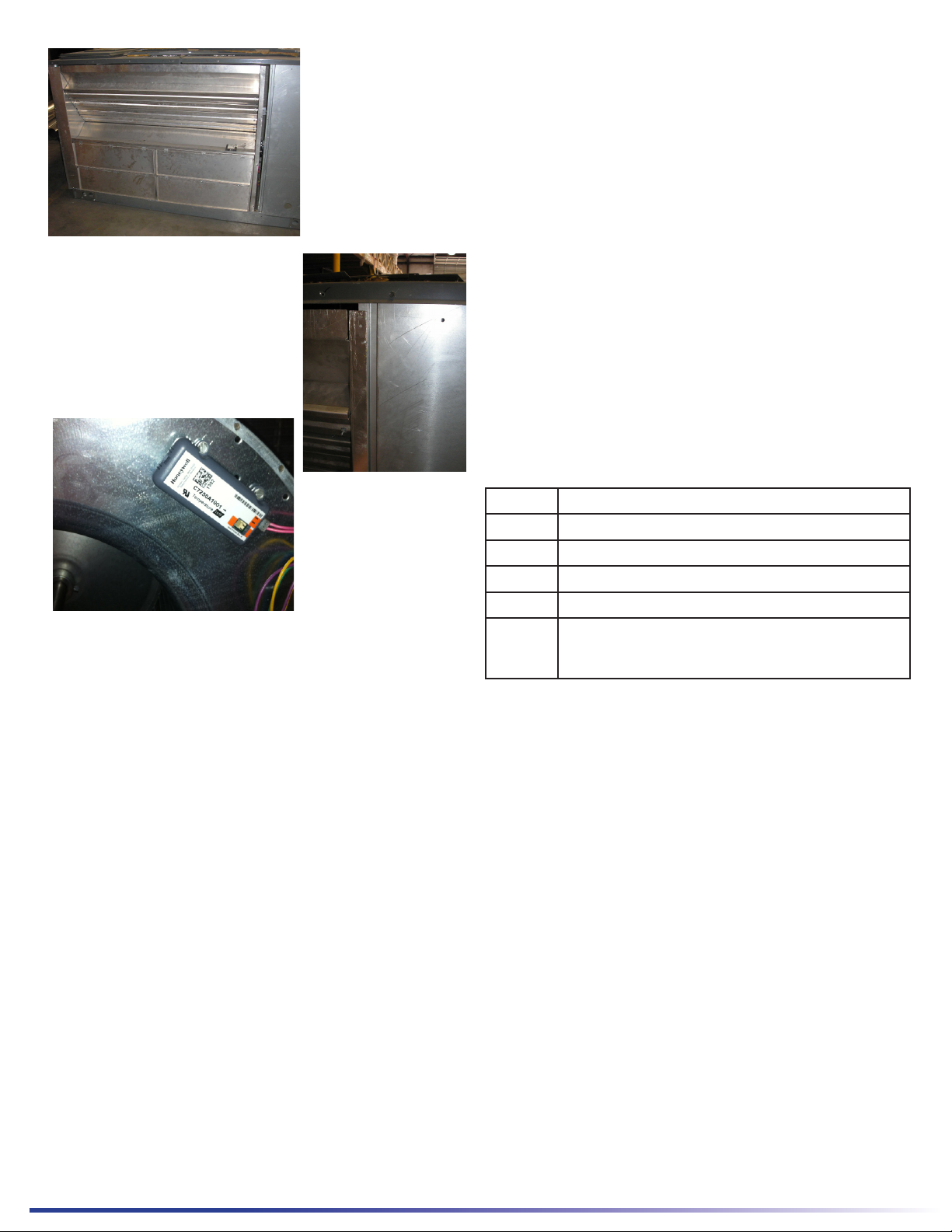
Figure 4
Figure 3
MINIMUM SET POINT EQUATION
(To X OA) + (Tr X RA) = Tm
To = Outdoor air temperature
OA= Percent of outdoor air
Tr = Return air temperature
RA= Percent of return air
Tm= Resulng mixed air temperature
Example:
Fresh air required is 10% outdoor air.
Outdoor air temperature is 60 degrees F.
Return air temperature is 75 degrees F.
(0.1 X 60) + (0.9 X 75) =
6.0 + 67.5 = 73.5
Mixed air temperature will be 73.5 degrees F when the
OA is 60 degrees F and the RA is 75 degrees F with 10%
outdoor air.
CONTENTS
Figure 5
6. Remove the mist eliminator lters from the fresh air/
barometric relief hood.
7. Install gasket material on the front of the top ange of
the hood assembly.
8. Install gasket material on the inside of the side anges
of the hood assembly.
9. Install the hood assembly taking care to slide the top
ange of the hood under the top cap of the unit.
10. Secure the hood with the screws provided.
11. Reinstall the mist eliminators and secure them using the
latches provided.
12. Locate the unit economizer 9 pin plug inside the evaporator secon near the lter access opening and plug it
into the corresponding 9 pin plug on the economizer.
NOTE: Ensure neither the wire nor the plugs interfere with
the movement of the dampers during operaon.
13. Remove the blower access panel on the unit and install
the mixed air sensor on the blower housing toward the
outside edge ensuring that the screws do not interfere
with the blower wheel. (Figure 5)
14. Connect the pink mixed air sensor wire to the sensor
and then feed the pink wire back to the Jade control and
connect it on the MAT terminal.
15. Seal the hood using silicone or other approved method
to ensure a water ght seal
16. Replace the blower and lter access panel.
1 Base plate
1 Damper rack w/ economizer controls
1 Fresh air hood
2 Mist eliminator
1 Screw package and control jumpers
1 Installation Instructions and Component
Manual
ACCESSORIES / CAPABILITIES
Dual Enthalpy - Requires an addional C7400 enthalpy
control installed in the return air duct.
Demand Control Venlaon - Requires a CO2 sensor.
Power Exhaust - DPE180240X power exhaust used in
applicaons where barometric relief is not sucient.
Important Notes
Please see enclosed brochure for Honeywell component
trouble shoong and conguraon instrucons.
The fresh air mist eliminator should be ushed periodically with warm soapy water.
A two stage thermostat is recommended with this accessory.
 Loading...