

McCulloch M12592RB, 96061016901 Parts Manual

REPAIR PARTS MANUAL
MODEL NO. M12592RB (96061016901)
Lawn Tractor
www.mcculloch.biz
532 41 38-33 Rev 1 05.14.08 AP/TH PRINTED IN U.S.A.

HOW TO USE THIS MANUAL
This manual is designed to provide the customer with a means to identify the parts on his/her tractor
when ordering repair parts. The illustrations may or may not represent the actual assemblies; therefore,
it is not recommended to use this manual as a guide to assemble or disassemble the tractor. Some
hardware and parts are drawn larger in order to more readily identify them.
Each tractor has its own model number.
The model number for your tractor can be found on the fender under the seat.
When ordering parts, always give the following information:
• Product - “Tractor”
• Model Number - “
• Part Number
• Part Description
M12592RB(96061016901)
”
TABLE OF CONTENTS
SCHEMATIC ................................................................................................................ 3
ELECTRICAL ............................................................................................................ 4-5
CHASSIS ..................................................................................................................6-7
DRIVE........................................................................................................................8-9
STEERING ............................................................................................................10-11
SEAT .......................................................................................................................... 12
DECALS ..................................................................................................................... 13
ENGINE ................................................................................................................. 14-15
MOWER DECK .....................................................................................................16-17
MOWER LIFT ........................................................................................................18-19
BAGGER ............................................................................................................... 20-21
2
TRACTOR- -MODEL NO. M12592RB (96061016901) PRODUCT NO. 960 61 01-69
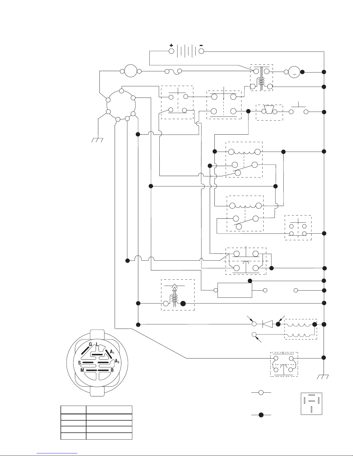
SCHEMATIC
03051_197438 (NO LIGHTS)
12VDC
STARTER
SOLENOID
STARTER
M
BLACK
RED
AMMETER
(OPTIONAL)
A
WHITE
RED
FUSE
15 AMP
BATTERY
RED
S
B
M
G
ACK
BL
A1
A2
L
ORANGE
RED
CLUTCH / BRAKE
(PEDAL UP)
GREEN
ATT'MENT CLUTCH
(CLUTCH OFF)
OPERATOR PRESENCE
85 86
87
OPERATOR PRESENCE
85 86
RELAY
RELAY
87
1
87A
2
FBI BUZZER
30
30
SWITCH
BLACK
FBI
IGNITION SWITCH
CIRCUITPOSITION
OFF
RUN/OVERRIDE
M+G+A1
B + S + A1START
B+A1
B+A1RUN
“MAKE”
L+A2
BLACK
GRAY
BLACK
BLACK
FUEL
LINE
BLUE RED
CARBURETOR SOLENOID
(IF SO EQUIPPED)
RED
CHARGING SYSTEM OUTPUT
3 AMP DC @ 3600 RPM
LIGHTING SYSTEM OUTPUT
5 AMP AC @ 3600 RPM
WIRING INSULATED CLIPS
NOTE: IF WIRING INSULATED CLIPS
WERE REMOVED FOR SERVICING OF
UNIT, THEY SHOULD BE REPLACED
TO PROPERLY SECURE YOUR WIRING.
03051
3
87A
SEAT SWITCH
(NOT OCCUPIED)
IGNITION
UNIT
REMOVABLE
CONNECTIONS
NON-REMOVABLE
CONNECTIONS
BAGGER
INTERLOCK
(NO BAG,
CHUTE OR
PLUG)
BLACK
GROUNDING
CONNECTOR
SPARK
PLUGS GAP
(2 PLUGS ON
TWIN CYL. ENGINES)
28 VOLTS AC MIN. @ 3600 RPM
(CHARGING SYSTEM DISCONNECTED)
DIODE
14 VOLTS AC MIN. @ 3600 RPM (LIGHTS OFF)
REVERSE SWITCH
ALTERNATOR
87
87A
RELAY
8586
30
33
30
28
29
26
24
42
43
25
41
27
27
27
40
197438
94
93
92
16
58
2
1
27
66
81
48
59
16
16
REPAIR PARTS
TRACTOR- -MODEL NO. M12592RB (96061016901) PRODUCT NO. 960 61 01-69
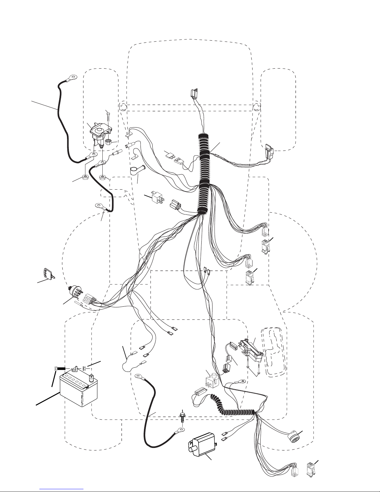
ELECTRICAL
4

REPAIR PARTS
TRACTOR- -MODEL NO. M12592RB (96061016901) PRODUCT NO. 960 61 01-69
ELECTRICAL
KEY PART
NO. NO. DESCRIPTION
1 532 16 34-65 Battery
2 874 76 04-12 Bolt Hex Hd 1/4-20 unc x 3/4
16 532 17 61-38 Switch Interlock
24 532 12 47-80 Cable Starter 6 Ga. 11" Red
25 532 16 59-87 Cable Battery Crd 56" Red
26 532 17 51-58 Fuse
27 873 51 04-00 Nut Keps Hex 1/4-20 unc
28 532 12 77-25 Cable Ground 6 Ga. 18" Black
29 532 19 27-49 Switch Seat
30 532 19 33-50 Switch Ignition
33 532 14 04-01 Key Ign Molded
40 532 19 74-38 Harness Ign
41 871 11 04-08 Bolt Flk Fin Hex 1/4-20 unc x 1/2
42 532 13 15-63 Cover Terminal Red
43 532 19 25-07 Solenoid
48 532 14 08-44 Adapter Ammeter Rectangular
58 532 16 94-19 Buzzer Crd
59 532 18 03-79 Switch FBI CRD
66 817 49 06-08 Screw Thdrol 3/8-16 x 1/2 Ty-Tt
81 532 10 97-48 Relay Asm
92 532 19 66-15 Harness Pigtail
93 532 19 25-40 Screw Plastite 10-14 x 2.0
94 532 19 18-34 Module Reverse
NOTE: All component dimensions given in U.S. inches.
1 inch = 25.4 mm.
5
REPAIR PARTS
TRACTOR- -MODEL NO. M12592RB (96061016901) PRODUCT NO. 960 61 01-69
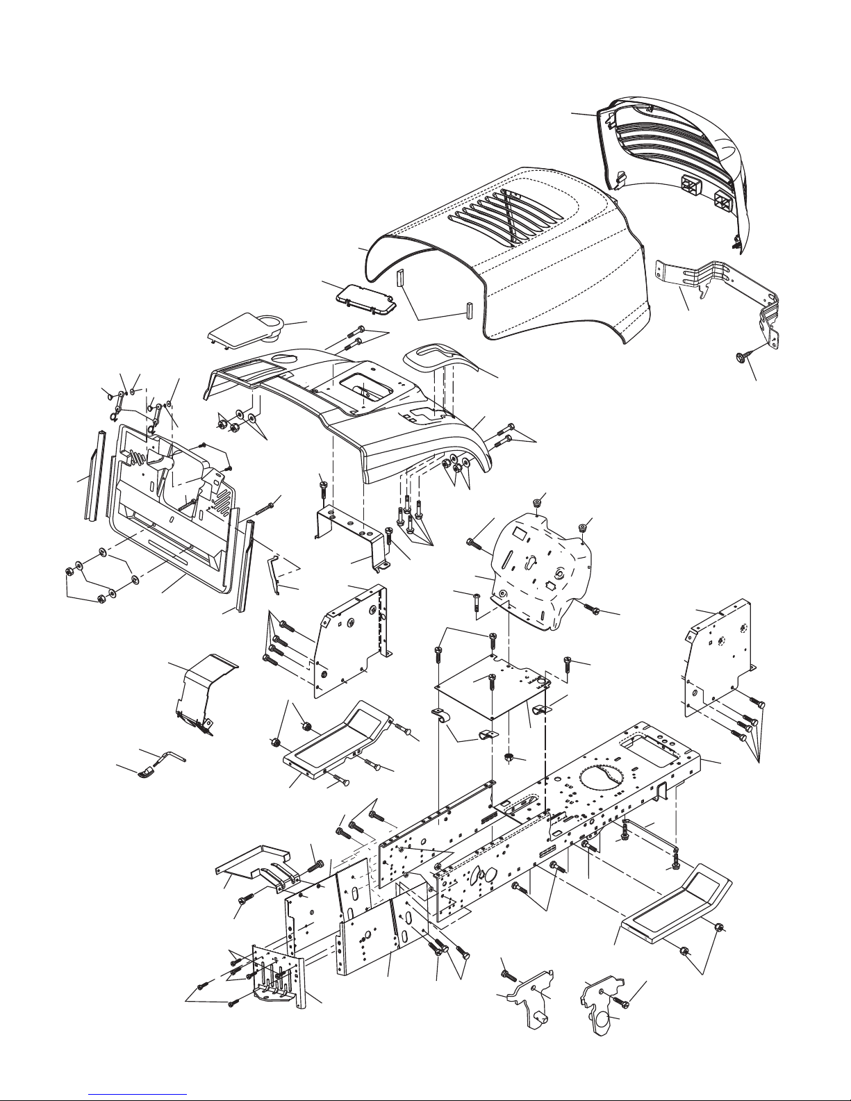
CHASSIS AND ENCLOSURES
28
17
256
266
173
172
187
189
186
198
188
187
170
175
188
189
171
26
265
190
25
208
171
26
184
165
209
11
31
24
18
209
69
15
209
26
25
3
39
89
30
24
5
209
9
5
209
209
8
13
278
179
185
33
164
3
209
207
209
205
6
16
35
209
37
34
38
205
145
37
26
1
208
209
35
10
209
3
162
2
24
163
26
209
8
24
26
38
chassis-Alpha_CRD_1
6

REPAIR PARTS
TRACTOR- -MODEL NO. M12592RB (96061016901) PRODUCT NO. 960 61 01-69
CHASSIS AND ENCLOSURES
KEY PART
NO. NO. DESCRIPTION
1 532 17 46-20 Chassis
2 532 18 03-84 Drawbar
3 817 06 06-12 Screw 3/8-16 x 3/4
5 532 15 52-72 Bumper Hood/Dash
6 532 18 44-19 Saddle
8 532 12 64-71 Clip Insulator 13/32 Mtg. Hole
9 532 19 46-88 Dash
10 872 14 06-08 Bolt, Carriage 3/8-16 x 3/4
11 532 17 49-96 Panel, Dash, L.H.
13 532 18 17-19 Panel, Asm. Dash R.H.
15 874 18 05-12 Screw, Machine, Truss Head
5/16-18 unc x 3/4
16 873 51 05-00 Nut
17 532 40 61-79 Hood
18 532 18 49-21 Bumper Hood
24 874 78 06-16 Bolt
25 819 13 13-12 Washer 13/32 x 13/16 x 12 Ga.
26 873 80 06-00 Nut
28 532 19 47-98 Grille
30 532 19 73-64 Fender
31 532 16 51-56 Bracket, Fender Support
33 532 18 25-07 Footrest, L.H.
34 532 18 25-08 Footrest, R.H.
35 872 11 06-06 Bolt
37 817 49 05-08 Screw Thdrol 5/16-18 x 1/2 TYT
38 532 18 17-48 Bracket Asm Pivot Mower Rear
39 532 18 75-68 Bracket Pivot
69 532 14 24-32 Screw HxWsh Hi-Lo
89 532 19 73-39 Console CRD 6 Sp. 418
145 532 40 91-67 Rod Pivot Chassis/Hood
KEY PART
NO. NO. DESCRIPTION
162 532 18 03-82 Bracket Exten Chassis Lh CRD
163 532 18 03-83 Bracket Exten Chassis Rh CRD
164 532 16 56-05 Support Battery CRD
165 532 18 13-56 Cover Battery
170 532 19 94-88 Backplate CRD
171 872 14 06-20 Bolt Rdhd Sqnk
3/8-16 x 2-1/2 Gr. 5
172 819 13 20-16 Washer 13/32 x 1-1/4 x 16 Ga.
173 873 51 06-00 Nut, Keps Hex 3/8-16 unc
175 532 18 82-03 Door Trap
179 532 18 82-02 Rod Pivot FBI CRD
184 532 17 46-62 Bracket Actuator Bagger CRD
185 532 18 11-01 Knob Rod Brake Parking
186 532 16 07-93 Latch Asm Mulch/Bagger
187 532 12 50-04 Nut Weld
188 819 06 12-16 Washer #10
189 810 07 10-00 Washer Lock #10
190 871 08 10-10 Screw Pan Hd Phillip 10-24 x 5/8
198 532 16 89-37 Nut, Push
205 817 49 06-08 Screw Thdrol 3/8-16 x 1/2
207 817 67 05-08 Screw Thdrl. 5/16-18 x 1/2
208 817 67 06-08 Screw Thdrol 3/8-16 x 1/2
209 817 00 06-12 Screw Hex Wsh Thdrol 3/8-16
256 532 18 13-61 Cover Fender Rack
265 532 18 57-04 Seal RH Side Bagger
266 532 18 57-03 Seal LH Side Bagger
278 532 19 16-11 Screw 10 x 3/4 Single Lead Hex
- - 532 00 54-79 Plug Button
- - 532 19 39-35 Plug Switch Light
NOTE: All component dimensions given in U.S. inches.
1 inch = 25.4 mm.
7
REPAIR PARTS
TRACTOR- -MODEL NO. M12592RB (96061016901) PRODUCT NO. 960 61 01-69
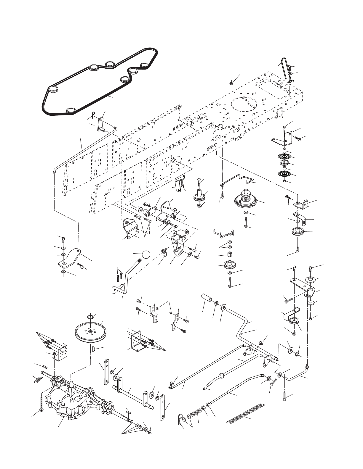
DRIVE
2
263
77
16
183
14
112
13
30
183
11
84
96
96
183
80
255
295
183
57
172
167
10
8
4
3
79
35
30
36
77
21
38
214
207
47
51
262
171
161
112
159
14
163
82
253
165
158
254
162
83
156
168
166
120
295
40
38
56
177
42
42
39
18
51
5
5
18
6
62
35
36
6
263
28
258
36
35
22
255
29
215
203
34
66
65
26
37
268
9
27
49
120
258
10
43
187
50
36
263
275
293
264
171
265
266
261
292
266
294
181
263
182
183
50
150
48
151
51
47
35
26
53
27
15
1
75
78
76
96
26
25
24
19
55
drive-CRD_D6800_fender_2_r1
8
 Loading...