

McCulloch 60012304 Parts List
I1lUSTIMTIDPfNITS11ST
hot-em:
MODEL NAME
EAGERBEAVER@
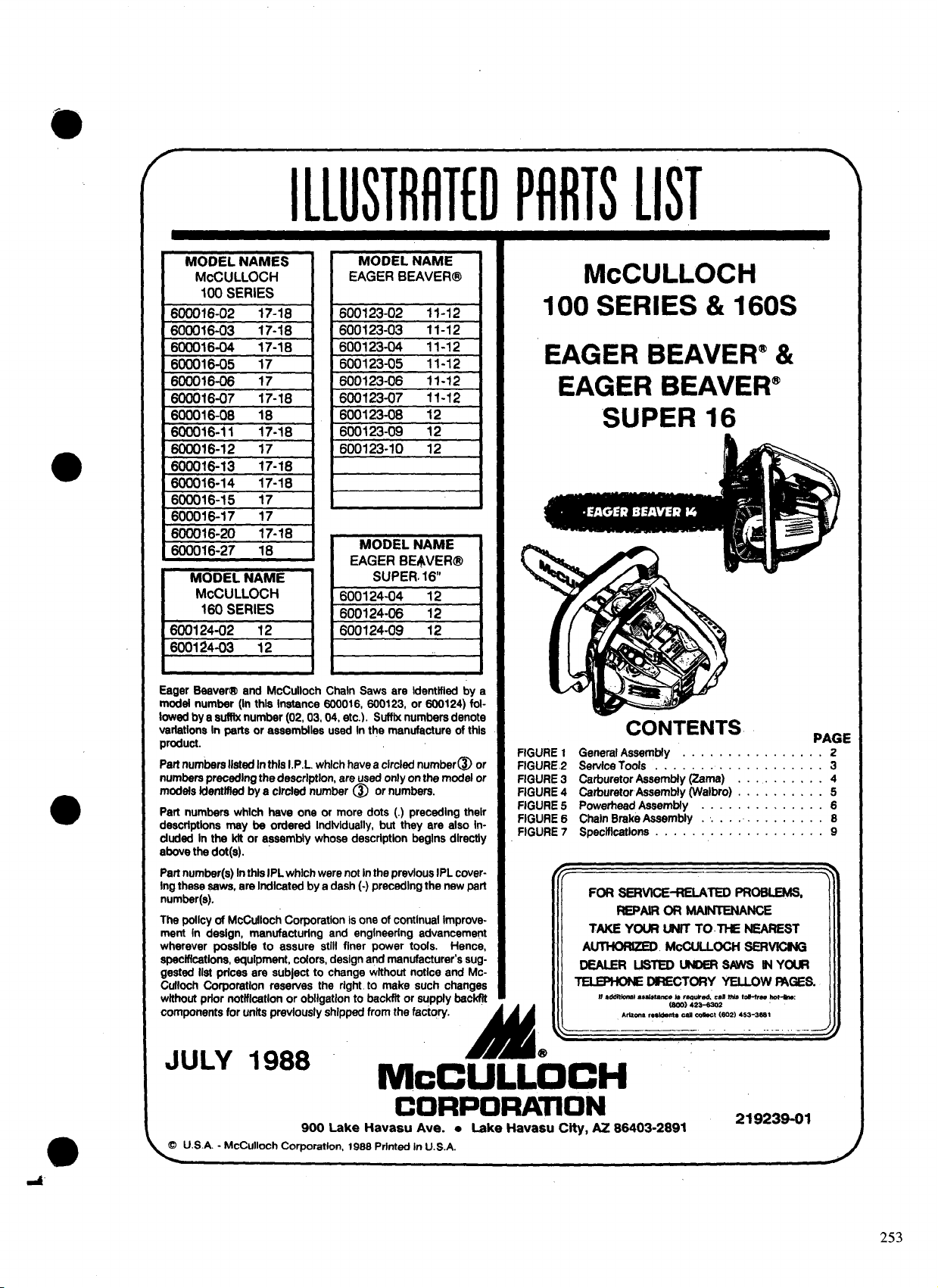
McCULLOCH
&OO16~02 “17-1%
600016-03
6ooo16-04
60i)O16-05 17
600016-06 17
600016-07
600016-06 18
600016-11
600016-12 17
600016-13
600016-14
600016-15 17
600016-17 17
600016-20
600016-27 18
Eager Beaver@ and McCulloch Chakr Sawa are identified by a
modal number (In this instance 600016, 600123, or 600124) followed by a suffix number (02, 03,04, etc.). Suffix numbers denote
variations In parts or assembles used In the manufacture of this
product.
Part numbers Iletad In thla I.P.L. which havea circled number@ or
numbers preceding the descrlptlon, are used only on the modal or
models identified by a circled number @ or numbers.
Part numbem which have one or more dots (.) preceding their
descrtptlons may be ordered Individually, but they are also lnduded In the kit or assembly whose description begins directly
above the dot(s).
Part number(s) In title IPL which were not in the previous IPL covering these aevva, are Indicated by e dash (-) preceding the new pert
number(s).
The poflcy of McCulkrch Corporation is one of continual improve-
ment in design, manufacturing and engineering advancement
wherever poesibie to assure stiil finer power tools. Hence,
specifications, equipment, colors, design and manufacturer’s suggested iist prices are subject to change without notice and Mc-
Cuiioch Corporation resewes the right to make such changes
without prior notification or obilgatlon to becirfil or supply backfit
components for units previously shipped from the factory.
17-18
17-18
17-16
17-18
17-18
17-18
17-18
600123-02
600123-03
600123-04
600123-05
600123-06
600123-07
600123-08 12
600123-09 12
600123-10 12
MODEL NAME
EAGERBEr$VER@
SUPER
600124-04 12
600124-06 12
600124-09 12
11-12
11-12
11-12
11-12
11-12
11-12
16
100 SERIES & 160S
EAGER BEAVER” &
EAGER BEAVER@
SUPER 16
—
CONTENTS
FIGURE 1
FIGURE 2
FIGURE 3
FIGURE 4
FIGURE 5
FIGURE 6
FIGURE 7
Generel Aseembly . . . . . . . . . . . . . ...2
Servkxlools . . . . . . . . . . . . . . . . . ..3
Carburetor Assembly (Zama) . . . . . . . . . 4
carburetor Assamtrly (Walbro) . . . . . . . . . . 5
PowerlmaciAsaambly.. . . . . . . . . . ...6
Chain Broke Assembiy . .. . . . . . . . . . ..8
Spectilcstlons . . . . . . . . . . . . . . . . ...9
MMdmnslsssbtmlw
Arllma ,e,ldmt, CM C099Ct (602) 453-3= t
L
.—— —.. —— ..- ..-. .—.
Ismlwkd,CaIMtd-hee
42 S-W302
(600)
PAGE
-J
JULY 1988
McCULLOCH
CORPORATION
900 Lake Havaau Ave. ● Lake Havasu City, AZ 86403-2891
@ U.S.A. - McCulloch Corporation, 198e Printed In U.S.A.
A’-
219239-01
253
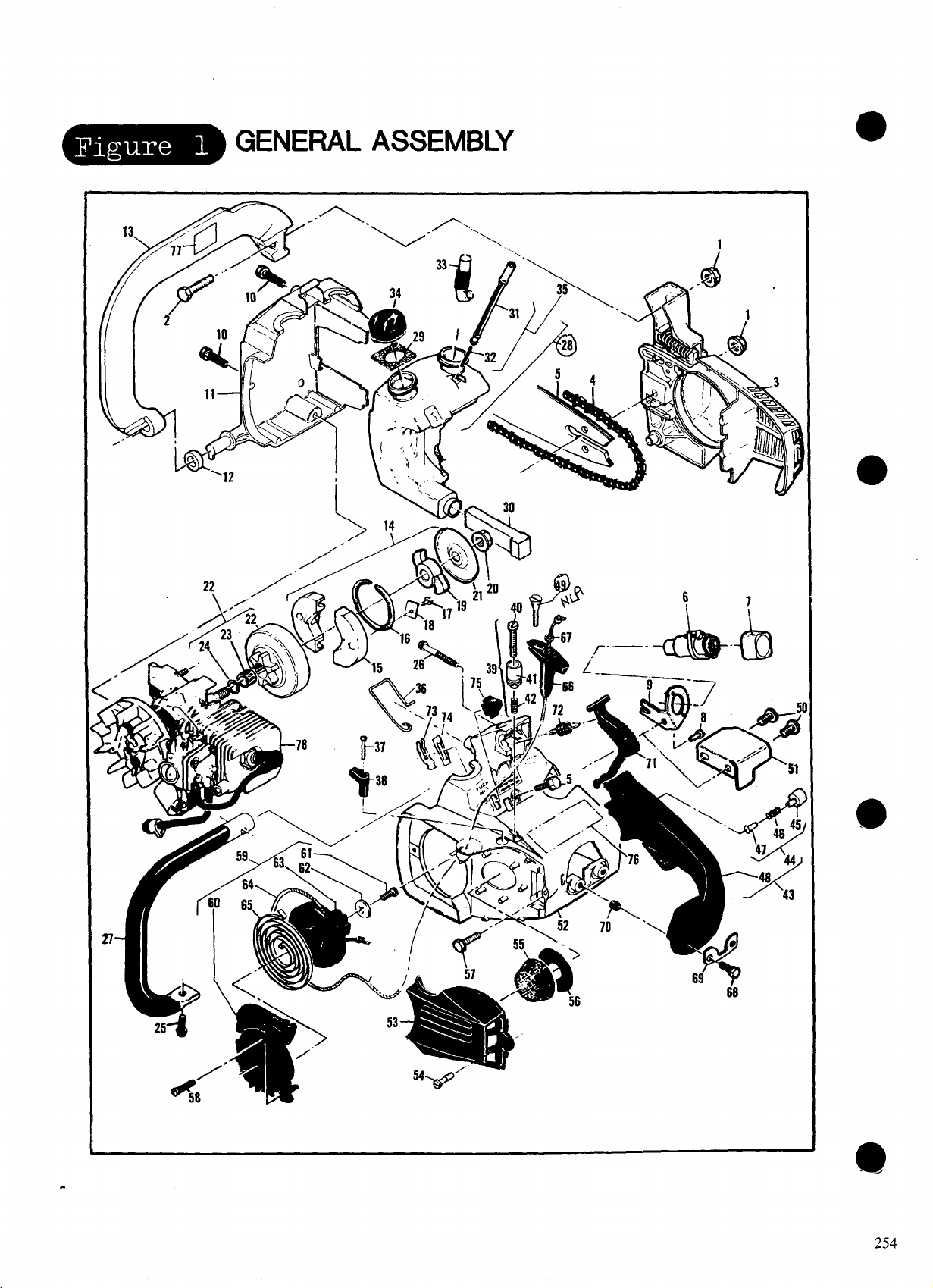
- GENERAL ASSEMBLY
● ✍
.
254
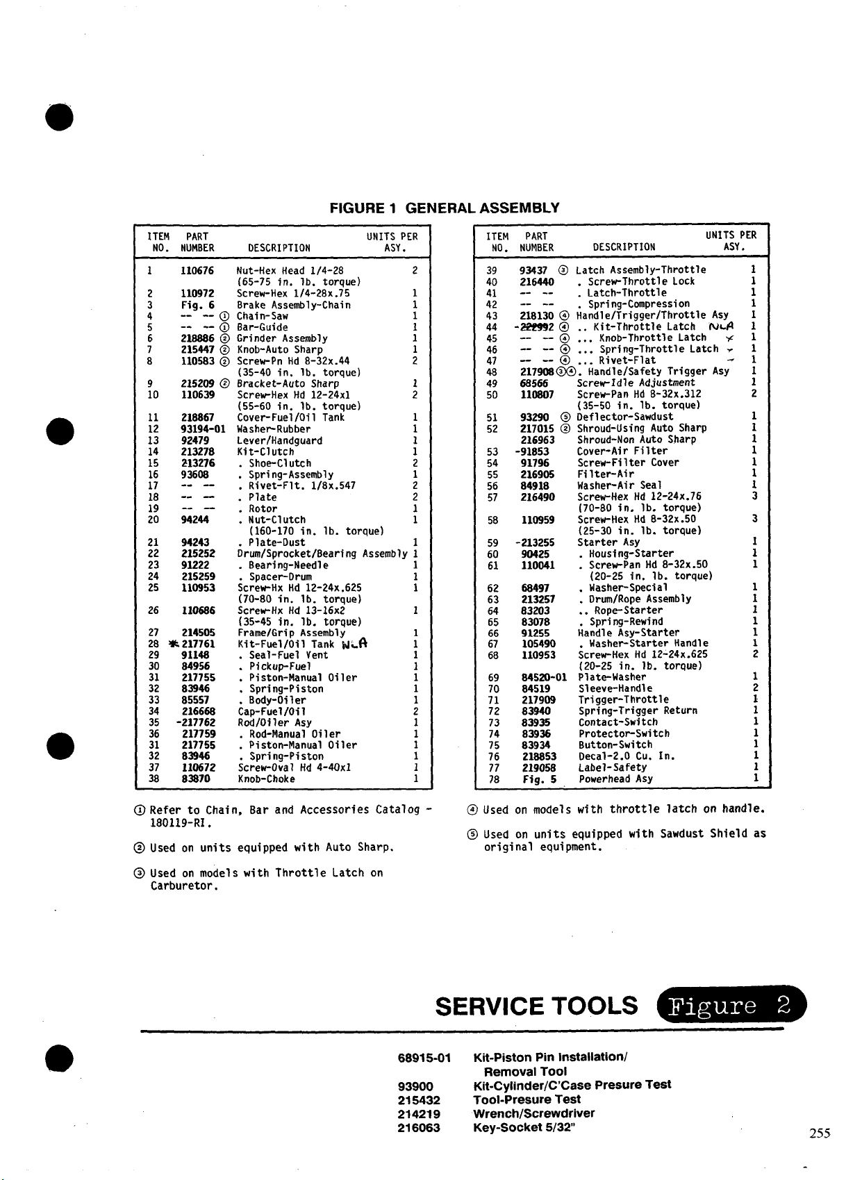
FIGURE1 GENERAL ASSEMBLY
ITEM PART UNITS PER
NO. NUMBER
1 110676
110972
: Fig. 6 Brake Assembly-Chain 1
--
4
5
6 21S886 @ Grinder Assembly :
7 215447 @ Knob-Auto Sharp
8 110583 @ Screw-Pn Hd 8-32x.44 ;
9 215209 @ Bracket-Auto Sharp
10 110639 Screw-Hex Hd 12-24x1
11 218867 Cover-Fuel/Oil Tank 1
i: 92479
14 213278
15 213276 .
16 9360S Spring-Assembly
17 -- -18 -- —
19 -- — ~ Rotor
20
21 94243
22 215252
23 91222 . Bearing-Needle 1
24 215259 Spacer-Drum
25
26
27
28 *217761
29
30
31
32
33
34
35 -217762 Rod/Oiler Asy
36
;:
:
--0 Chain-Saw
--
--@ Bar-Guide
93194-01 Washer-Rubber 1
94244 . Nut-Clutch 1
110953
1106S6
214505
9114s
84956
217755
83946 : Spri rig-Piston 1
B5557
216668
217759 Rod-Manual Oi 1er 1
217755
B3946
110672 ;crew-Oval Hd 4-40x1
83870
DESCRIPTION
Nut-Hex Head 1/4-28
(65-75 in. lb. torque)
Screw-Hex 114-28x.75 1
(35-40 in. lb. torque)
(55-60 in. lb. torque)
Lever/Handguard
Kit-Clutch
Shoe-Cl utch 2
: Rivet-Fit. l/8x.547 ;
Plate
(160-170 in. lb. torque)
Plate-Dust
&um/Sprocket/8earing Assembly 1
;crew-Hx Hd 12-24x.625
(70-80 in. lb. torque)
Screw-Hx Hd 13-16x2
(35-45 in. lb. torque)
Frame/Grip Assembly
Kit-Fuel/Oil Tank wkfi
Seal-Fuel Vent 1
: Pickup-Fuel
Piston-Manual Oi 1er
8ody-Oiler 1
~ap-Fuel /Oi 1 2
: Piston-Manual Oiler
Spri rig-Piston
Knob-Choke 1
ASY.
PART
ITEM
NO. NUMBER
2
1
:
1
1
2
1
1
1
1
1
:
1
1
1
1
1
1
39
93437 @ Latch Assembly-Throttle
40
216440
-- --
-- --
:;
218130 @ ;andle/Trigger/Throttle Asy
43
44
-222992 @
--
45
46
47
48
49
50
51
52
53
54
55
56
57
5B
59
60
61
62
63
64
65
66
67
68
69
70
71
72
73
14
;;
77
18
-- @
--
--@ . . .
--
-- @
21790S@@. Handle/Safety Trigger
68566
11OBO7
9329o @ Oeflector-Sawdust
217015 @ Shroud-Using Auto Sharp
216963 Shroud-Non Auto Sharp
-91B53
91796
216905
84918
216490
110959
-213255
90425
110041
213%7
83203
8307B
91255
105490
110953
S4520-01
84519
217909
83940
83935
83936
83934
21SS53
219058
Fig. 5
DESCRIPTION ASY.
. Screw-Throttle Lock
. Latch-Throttle
Spring-Compression
. . Kit-Throttle Latch fw-#
. . . Knob-Throttle Latch w
Spring-Throttle Latch ~
. . . Rivet~Flat
Screw-idle Adjustment
Screw-Pan Hd 8-32x.312
(35-50 in. lb. torque)
Cover-Air Filter
Screw-Filter Cover
Filter-Air
Washer-Air Seal
Screw-Hex Hd 12-24x.76
(70-BO in. lb. torque)
Screw-Hex Hd 8-32x.50
(25-30 in. lb. torque)
Starter AsY
Housi rig-Starter
Screw-Pan Hd B-32x.50
.
(20-25 in. lb. torque)
Washer-Special
.
Drum/Rope Assembly
.
Rope-Starter
. .
Spring-Rewind
~andle Asy-Starter
. Washer-Starter Handle
Screw-Hex Hd 12-24x.625
(20-25 in. lb. torque)
Plate-Washer
Sleeve-Handle
Trigger-Throttle
Spring-Trigger Return
Contact-Switch
Protector-Switch
Button- Switch
Decal-2.O Cu. In.
Label-Safety
Powerhead AsY
UNITS PER
Asy
1
1
1
1
;
1
1
1
1
1
1
1
1
1
1
2
1
1
1
1
1
(l) Refer to Chain, Bar and Accessories Catalog
180119-RI .
@Used on units equipped with Auto Sharp.
@Used on models with Throttle Latch on
Carburetor.
@Used on models with throttle latch on handle.
@Used on units equipped with Sawdust Shield as
original equipment.
SERVICETOOLS
68915-01
93900
215432
214219
216063
Kit-Piston Pm installation/
Removal Tool
Kit-Cylinder/C’Case PresureTest
Tool-PresureTest
Wrench/Screwdriver
Key-Socket5/32
255
 Loading...