

McCulloch 32CC TRIMMER Service Manual

Service Manual
NOTE: These materials are for use by trained technicians who are experienced in the service and repair of outdoor power
equipment of the kind described in this publication, and are not intended for use by untrained or inexperienced individuals.
These materials are intended to provide supplemental information to assist the trained technician. Untrained or inexperienced
individuals should seek the assistance of an experienced and trained professional. Read, understand, and follow all instructions
and common sense when working on power equipment. This includes the contents of the product’s Operators Manual, supplied
with the equipment. No liability can be accepted for any inaccuracies or omission in this publication, although care has been
taken to make it as complete and accurate as possible at the time of publication. However, due to the variety of outdoor power
equipment and continuing product changes that occur over time, updates will be made to these instructions from time to time.
Therefore, it may be necessary to obtain the latest materials before servicing or repairing a product. The company reserves the
right to make changes at any time to this publication without prior notice and without incurring an obligation to make such
changes to previously published versions. Instructions, photographs and illustrations used in this publication are for reference
use only and may not depict actual model and component parts. © Copyright 2005 MTD Products Inc. All Rights Reserved
MTD Products LLC - Product Training and Education Department
32cc String Trimmer
Power Head
IMPORTANT: READ SAFETY RULES AND INSTRUCTIONS CAREFULLY
This Service Manual is not a substitute for the Operator’s Manual. You must read, understand
and follow all of the directions in this manual as well as the Operator’s Manual before working
on this power equipment.
MCCULLOCH CORPORATION P.O. BOX 31567, TUCSON, AZ 85751-1567
PRINTED IN USA
FORM NO. 769-00942
(10/2003)

McCulloch 32cc Trimmer
1. INTRODUCTION
North American distribution rights to the McCulloch
product line are new to MTD for the 2004 season. The
trimmers are similar in some ways to the MTD SouthWest (RYOBI) products that we have offered for the
past three years.
The architecture of both units is based on a cantilever
crankshaft. The McCulloch is piston ported, while the
MTDSW engine has a reed valve. Some of the service
techniques are similar, but not identical.
2. TRIMMER HEADS
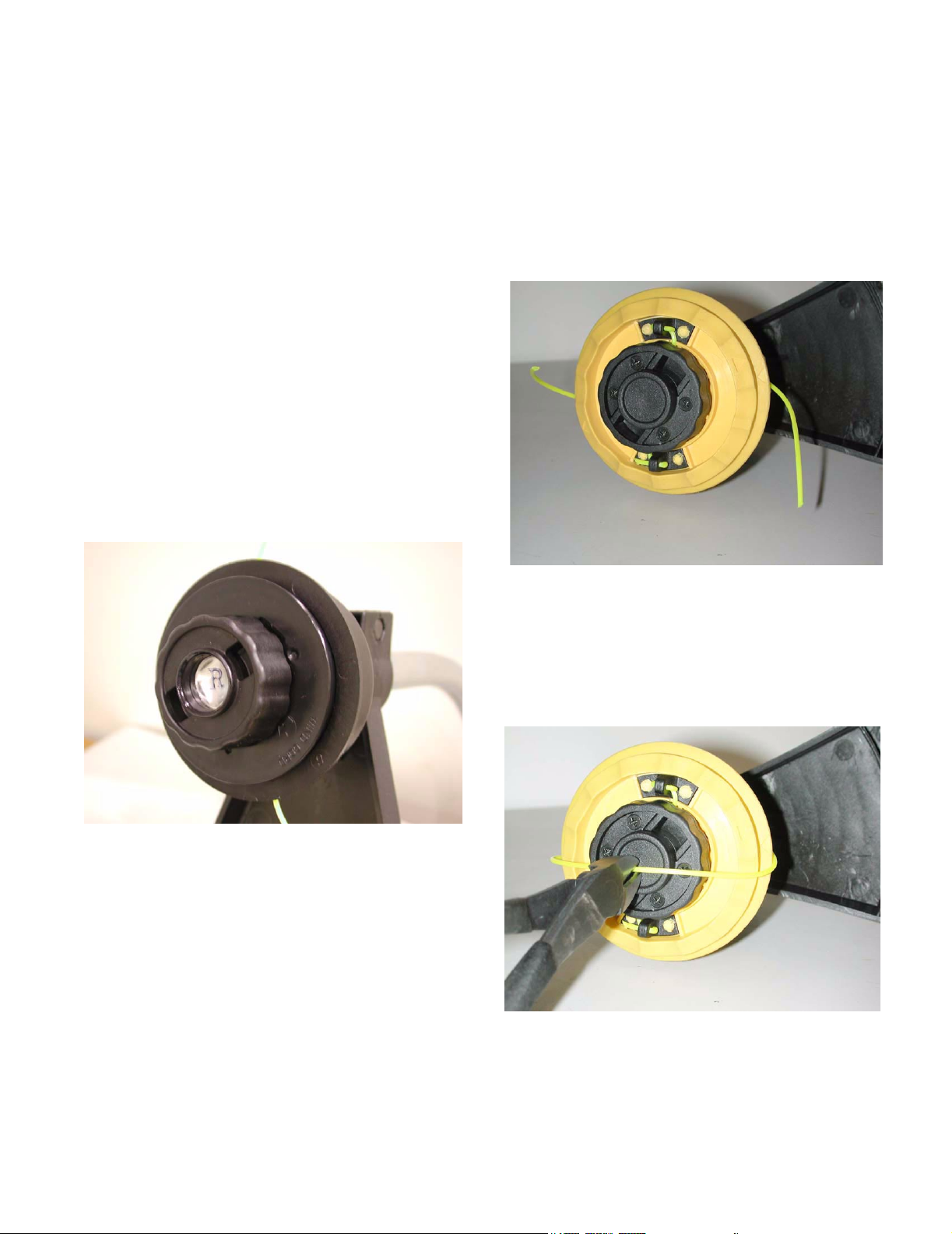
2.1. One trimmer head available on the McCulloch
products is nearly identical to the MTDSW TapN-Go. The operating principle is the same, but
the parts are different enough that they are not
fully interchangeable. See Figure 2.1.
McCulloch version
of small tap-n-go
2.3. Another trimmer head that is used on McCulloch
string trimmers resembles a cross between the
MTDSW Speed Spool and the MTDSW Tap-NGo head. See Figure 2.3.
McCulloch trimmer head with
simplified loading
Figure 2.3
2.4. A refill consists of 15’ - 20’ of .080” trimmer line.
2.5. To install line, cut it to length. Two equal-length
half-portions may be used, or one full length line
may be installed, then trimmed after installation.
See Figure 2.5.
Figure 2.1
2.2. There is also a McCulloch version of the large
tap-n-go head. It is used on the straight shaft
trimmers, and rotates in the opposite direction of
the small one.
Single-length method
Figure 2.5
1
McCulloch 32cc Trimmer
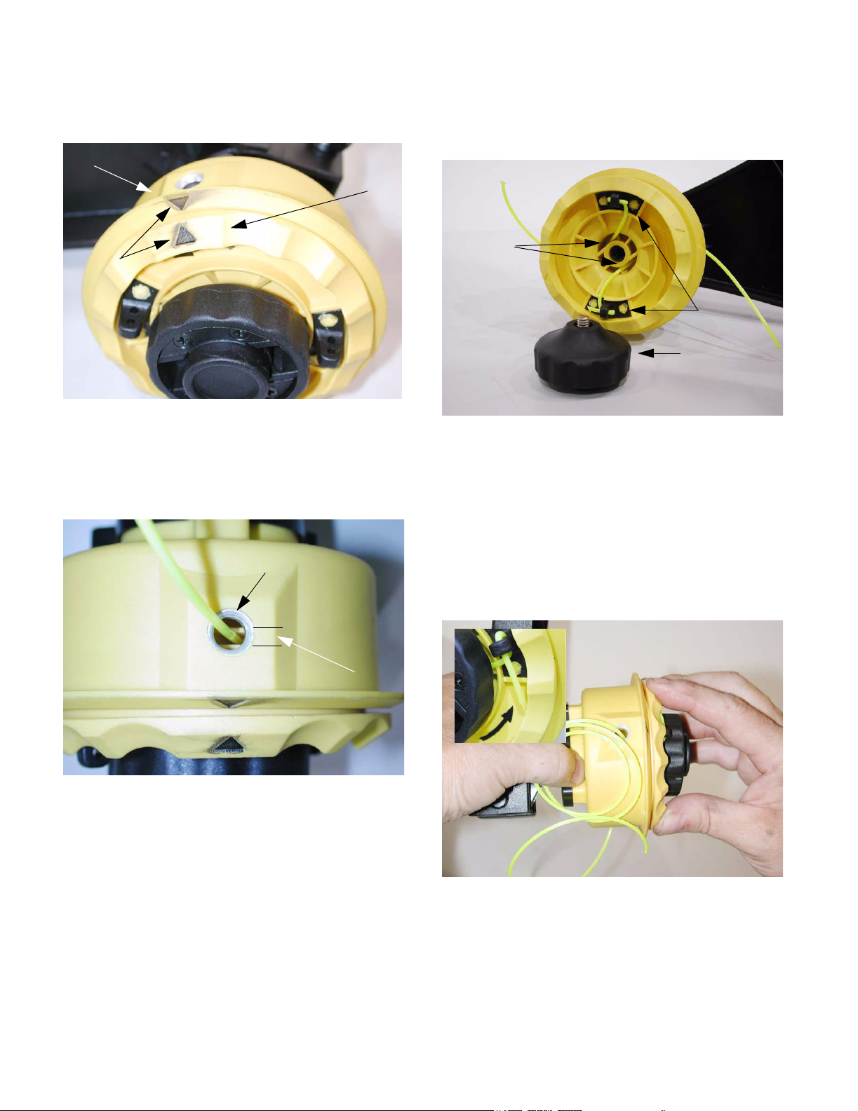
2.6. Align the arrows on the spool with the arrows on
the housing. See Figure 2.6.
Housing
Spool
Arrows
(marked for
clarity)
Figure 2.6
2.7. Insert a length of trimmer line through each eyelet. There are two sheaves for line in the spool,
separated by a narrow groove. The line must
enter the narrow groove. See Figure 2.7.
2.8. From the eyelet, the line will be channeled up
under the bump knob by a set of ramps in the
spool. See Figure 2.8.
Ramps
Bump knob
removed for
clarity
Figure 2.8
2.9. The ends of the line are looped-through the
anchors to hold them in place, then pulled-tight.
NOTE: With the arrows aligned, the line can also
be installed from the inside-out, by removing the
bump knob.
Anchors
Bump knob
Eyelet
Center
groove
Figure 2.7
2.10. The final step is to rotate the spool in the direction indicated by the arrows, drawing the line into
the head. See Figure 2.10.
Inset: arrow on spool, marked
for clarity
Figure 2.10
2.11. Stop winding when each end of the line is about
6” long.
2.12. Press the bump knob and pull on the line to
manually test the trimmer head. Do not push the
housing off it’s seat while testing.
2
McCulloch 32cc Trimmer
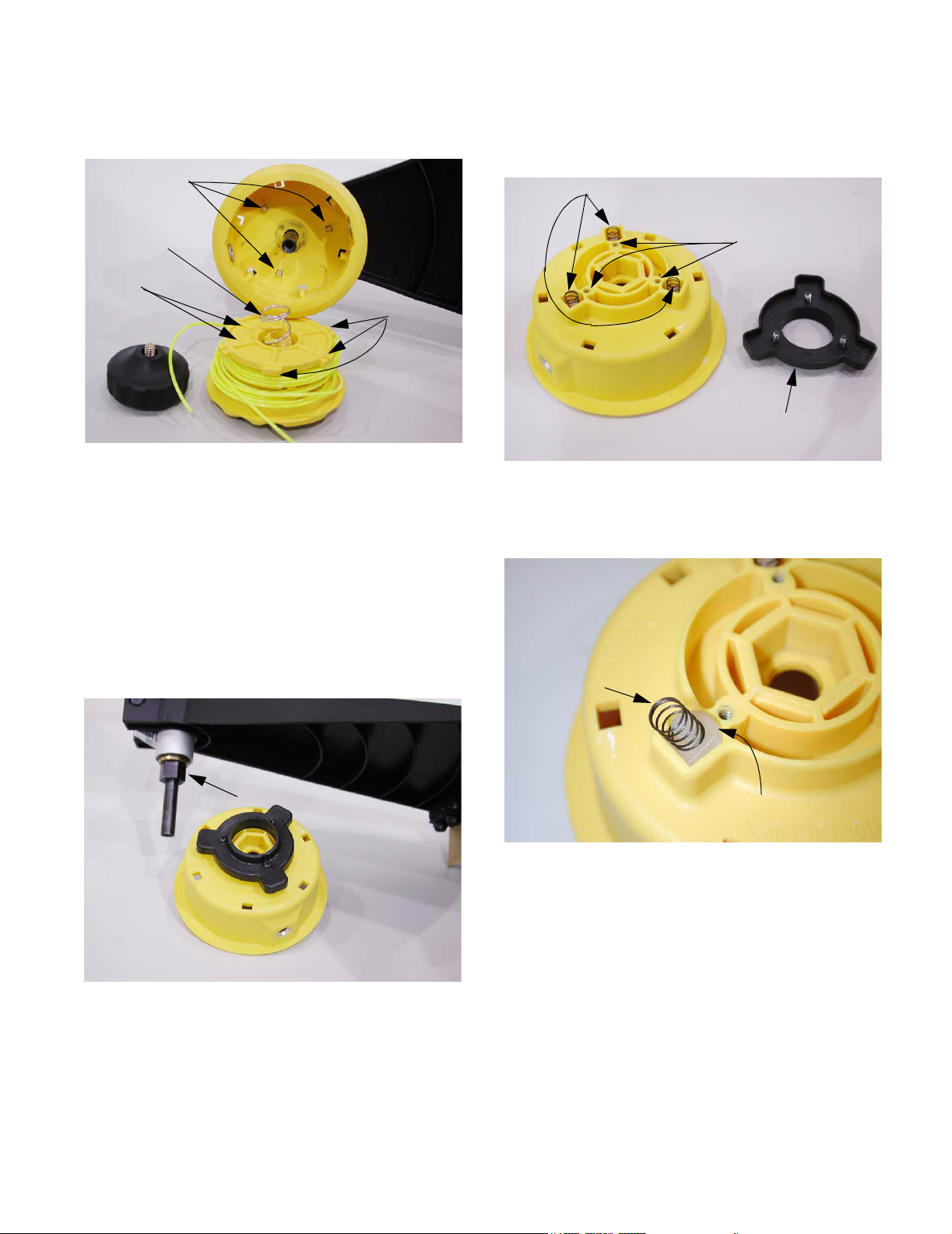
2.13. If repair is required, remove the bump knob, and
withdraw the spool. See Figure 2.13.
Ratchet wedges
Spring
Ribs
Tab s
Figure 2.13
2.14. Check for: tangled line, damaged tabs on the
spool, worn ribs on the spool, missing spring,
broken ratchet wedges.
2.15. Replace the spool if it is worn or damaged.
2.17. The ratchet wedges can be serviced by removing the three screws holding the black cover to
the top of the housing. See Figure 2.17.
Small springs behind
Holes for screws
Cover
Figure 2.17
2.18. Carefully remove the springs, and pull out the
wedges. See Figure 2.18.
NOTE: Bump knobs are a wearable item, and
are replaced in the course of normal use.
2.16. The housing is not fastened to the boom. It simply rests over a hexagonal drive collar.
See Figure 2.16.
Drive collar
Figure 2.16
Spring seats over
post on back of wedge
One rounded side,
insures correct orientation
Figure 2.18
3
McCulloch 32cc Trimmer
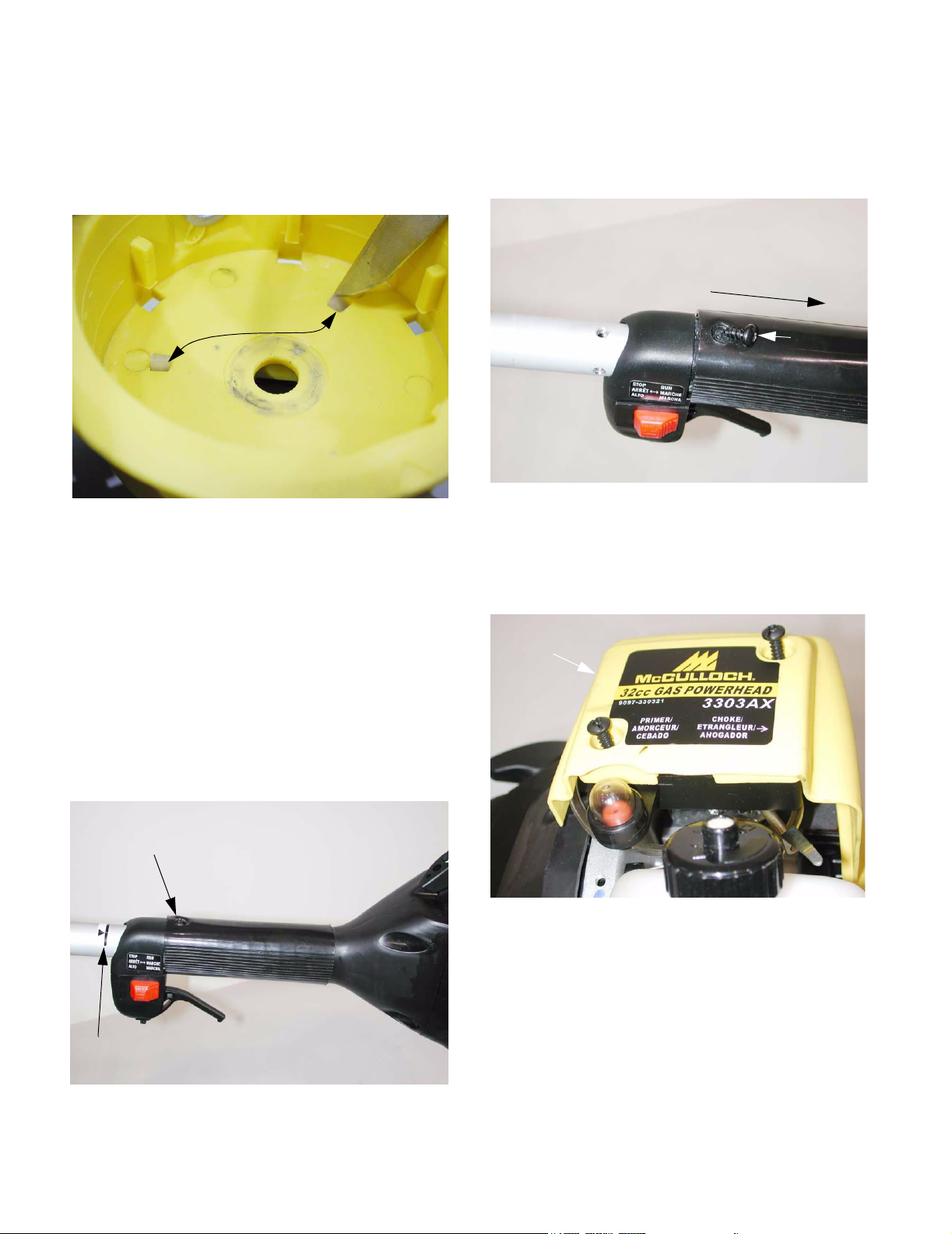
2.19. When properly installed, the wedges should be
spring loaded. They retract when the ribs on the
back of the spool pass them, then extend to
keep the spool from rotating backwards.
See Figure 2.19.
Spring loaded
ratchet wedges
Figure 2.19
3. RECOIL STARTER
3.3. To separate the powerhead from the boom,
remove the screw at the top of the grip using a T25 driver, then withdraw the boom.
See Figure 3.3.
Trigger housing and
grip slip off of boom
Screw
removed
Figure 3.3
3.4. Remove the air filter cover using a T-25 driver to
gain access to the connection between the throttle cable and the throttle arm on the carburetor.
See Figure 3.4.
3.1. Next to the cutting head, this is probably the
most common service item on the trimmer. It is
similar in principle to the MTDSW starter, but the
routing of the throttle and stop switch cables
necessitates a slightly different approach.
3.2. The throttle trigger, stop switch, and grip can all
be removed from the boom in unit with the
power-head. See Figure 3.2.
Screw holds grip
and Throttle housing
to boom
Positioning mark
Air filter
cover
Figure 3.4
Figure 3.2
4
 Loading...