

Page 1

REPAIR PARTS MANUAL
MODEL NO. 17107 (BA17107C)
Lawn Tractor
532 19 19-88 Rev. 1 12.10.04 RD/TR
Printed in U.S.A.
Page 2

HOW TO USE THIS MANUAL
This manual is designed to provide the customer with a means to identify the parts on his/her tractor
when ordering repair parts. The illustrations may or may not represent the actual assemblies; therefore,
it is not recommended to use this manual as a guide to assemble or disassemble the tractor. Some
hardware and parts are drawn larger in order to more readily identify them.
Each tractor has its own model number.
The model number for your tractor can be found on the fender under the seat.
When ordering parts, always give the following information:
• Product - “Tractor”
• Model Number -
• Part Number
• Part Description
17107 (BA17107C)
TABLE OF CONTENTS
SCHEMATIC ................................................................................................................3
ELECTRICAL............................................................................................................4-5
CHASSIS...................................................................................................................6-7
DRIVE........................................................................................................................8-9
STEERING ............................................................................................................10-11
ENGINE.................................................................................................................12-13
SEAT ..........................................................................................................................14
DECALS.....................................................................................................................15
MOWER LIFT........................................................................................................16-17
MOWER DECK .....................................................................................................18-19
2
Page 3
TRACTOR - - MODEL NO. 17107 (BA17107C), PRODUCT NO. 964 77 33-02
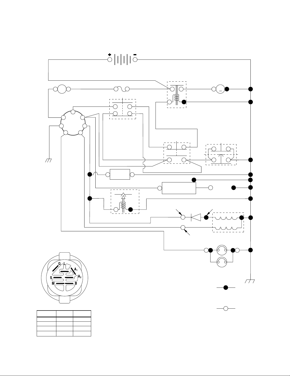
SCHEMATIC
A
AMMETER
(OPTIONAL)
RED
B
G
L
IGNITION
SWITCH
BLACK
RED
BLACK
BATTERY
RED
FUSE
WHITE
RED
M
STARTER
BLACK
SOLENOID
S
M
A1
CLUTCH / BRAKE
(PEDAL UP)
WHITE
A2
SEAT SWITCH
(NOT OCCUPIED)
BLACK
GROUNDING
CONNECTOR
SPARK
PLUG
GAP
(2 PLUGS ON
TWIN CYL. ENGINES)
28 VOLTS AC MIN. @ 3600 RPM
(CHARGING SYSTEM DISCONNECTED)
ALTERNATOR
BLACK
BLACK
BLACK
HOUR
METER
(OPTIONAL)
FUEL
BLUE
FUEL SHUT-OFF SOLENOID
(IF SO EQUIPPED)
LINE
ORANGE
WHITE
ATT'MENT CLUTCH
(CLUTCH OFF)
BLACK
BLACK
CHARGING SYSTEM OUTPUT
3 AMP DC @ 3600 RPM
RED
LIGHTING SYSTEM OUTPUT
5 AMP AC @ 3600 RPM
IGNITION
UNIT
DIODE
IGNITION SWITCH
CIRCUITPOSITION
OFF
M+G+A1
B+A1RUN/LIGHT
B+A1RUN
B+S+A1START
“MAKE”
NONE
A2+L
NONE
NONE
14 VOLTS AC MIN. @ 3600 RPM (LIGHTS OFF)
NOTE
YOUR TRACTOR IS
EQUIPPED WITH A SPECIAL
BROWN
ALTERNATOR SYSTEM.
THE LIGHTS ARE NOT
CONNECTED TO THE
BATTERY, BUT HAVE THEIR
OWN ELECTRICAL SOURCE.
BECAUSE OF THIS, THE
BRIGHTNESS OF THE LIGHTS
WILL CHANGE WITH ENGINE
SPEED. AT IDLE THE LIGHTS
WILL DIM. AS THE ENGINE IS
SPEEDED UP, THE LIGHTS
WILL BECOME THEIR BRIGHTEST.
WIRING INSULATED CLIPS
NOTE: IF WIRING INSULATED CLIPS WERE REMOVED FOR
SERVICING OF UNIT, THEY SHOULD BE REPLACED TO
PROPERLY SECURE YOUR WIRING.
02363
3
BLACK
HEADLIGHTS
NON-REMOVABLE
CONNECTIONS
REMOVABLE
CONNECTIONS
Page 4
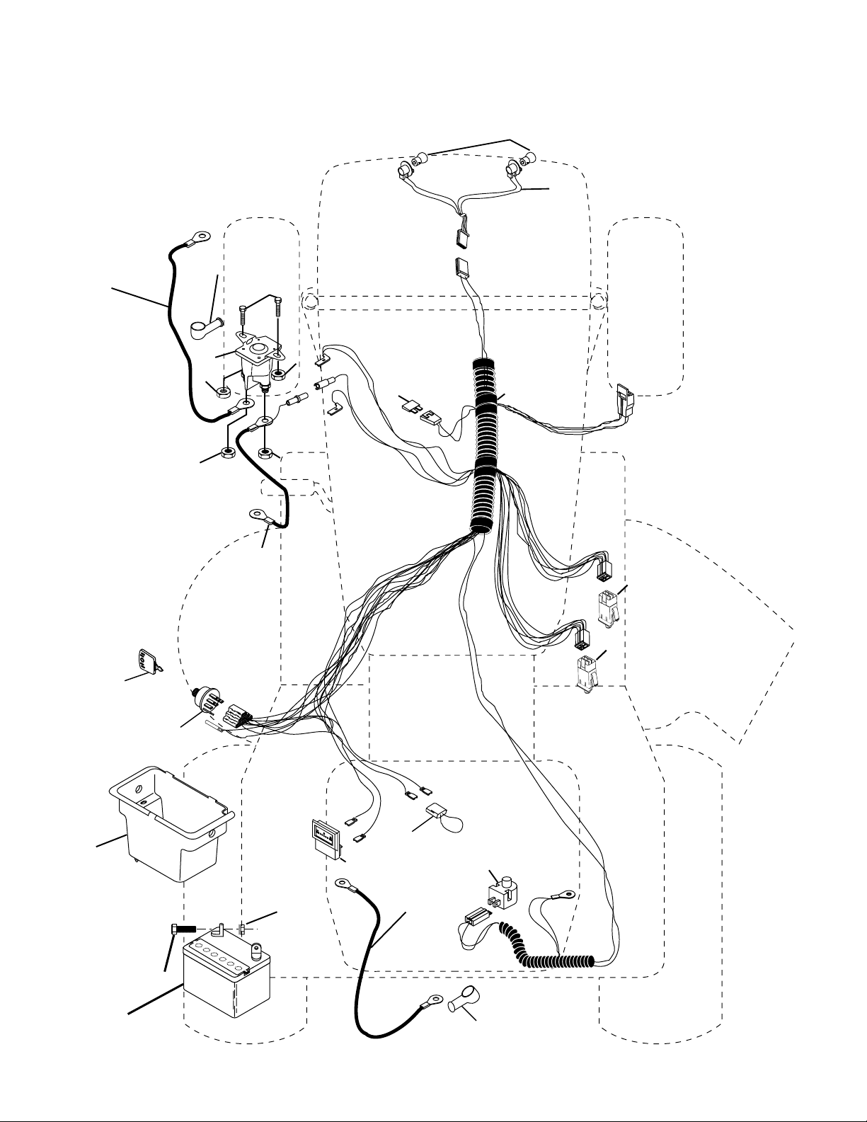
REPAIR PARTS
TRACTOR - - MODEL NO. 17107 (BA17107C), PRODUCT NO. 964 77 33-02
ELECTRICAL
22
21
42
24
41
33
30
27
43
27
25
27
27
26
40
16
16
D
.
C
.
A
M
P
E
R
E
8
S
45
27
52
29
28
2
1
90
4
Page 5

REPAIR PARTS
TRACTOR - - MODEL NO. 17107 (BA17107C), PRODUCT NO. 964 77 33-02
ELECTRICAL
KEY PART
NO. NO. DESCRIPTION
1 532 16 34-65 Battery 12 Volt 25 Amp
2 874 76 04-12 Bolt Hex Hd 1/4-20 unc x 3/4
8 532 17 66-89 Case Battery Mech Hinge
16 532 17 61-38 Switch Interlock Push-In
21 532 18 37-59 Harness Asm Light W/4152j
22 532 00 41-52 Bulb Light #1156
24 532 12 47-80 Cable Battery 6 Ga. 11"red
25 532 14 61-47 Cable Battery
26 532 17 51-58 Fuse
27 873 51 04-00 Nut Keps Hex 1/4-20 unc
28 532 12 47-73 Cable Ground 6 Ga. 12"black
29 532 12 13-05 Switch Plunger Nc Gray
30 532 17 55-66 Switch Ign
33 532 14 04-01 Key Ign
40 532 17 97-20 Harness Ign
41 871 11 04-08 Bolt Blk Fin Hex 1/4-20
42 532 13 15-63 Cover Terminal Red
43 532 17 88-61 Solenoid
45 532 12 14-33 Ammeter
52 532 14 19-40 Protection Wire Loop
90 532 18 04-49 Cover Terminal Battery
NOTE: All component dimensions given in U. S.
inches 1 inch = 25.4 mm.
5
Page 6
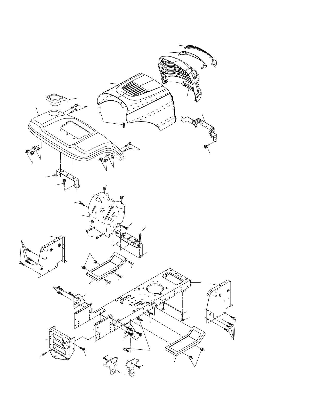
REPAIR PARTS
TRACTOR - - MODEL NO. 17107 (BA17107C), PRODUCT NO. 964 77 33-02
CHASSIS
29
212
17
208
26
30
25
31
11
209
209
159
9
207
24
18
26
28
39
24
278
25
5
5
209
208
206
26
209
209
2
33
142
209
35
10
142
14
38
209
14
64
209
35
37
34
145
37
26
1
13
208
chassis_elite value_stlt_3
6
Page 7

REPAIR PARTS
TRACTOR - - MODEL NO. 17107 (BA17107C), PRODUCT NO. 964 77 33-02
CHASSIS
KEY PART
NO. NO. DESCRIPTION
1 532 17 46-19 Chassis
2 532 17 65-54 Drawbar
5 532 15 52-72 Bumper Hood Dash
9 532 19 11-16 Dash
10 872 14 06-08 Bolt Rdhd Sqnk 3/8-16 unc x 1
11 532 17 49-96 Panel Dash LH
13 532 18 69-52 Panel Dash RH
14 817 49 06-08 Screw Thdrol 3/8-16 x 1/2
17 532 18 65-80 Hood
18 532 12 69-38 Bumper Hood
24 874 78 06-16 Bolt Fin Hex 3/8-16 unc x 1 Gr. 5
25 819 13 13-12 Washer 13/32 x 13/16 x 12 Ga.
26 873 80 06-00 Nut Lock Hex w/Ins 3/8-16 unc
28 532 18 35-52 Grille/Lens Asm (Includes Key Nos. 29 and 212)
29 532 18 58-46 Lens Grille
30 532 18 56-34 Fender
31 532 13 66-19 Bracket Fender Repl 109873X
33 532 18 25-07 Footrest Pnt LH
34 532 18 25-08 Footrest Pnt RH
35 872 11 06-06 Bolt Rdhd Sht Sqnk 3/8-16 x 3/4
37 817 49 05-08 Screw Thdrol 5/16-18 x 1/2 Tyt
38 532 17 57-10 Bracket Asm Pivot Mower Rear
39 532 17 47-14 Bracket, Pivot
64 532 15 47-98 Dash Lower STLT
142 532 17 57-02 Plate Reinforcement STLT
145 532 15 65-24 Rod Pivot Chassis/Hood
159 532 18 56-35 Cupholder
206 532 17 01-65 Bolt Shoulder 5/16-18
207 817 67 05-08 Screw Thdrol 5/16-18 x 1/2
208 817 67 06-08 Screw Thdrol 3/8-16 x 1/2
209 817 00 06-12 Screw 3/8-16 x 3/4
212 532 18 35-50 Insert Lens Refl ective
278 532 19 16-11 Screw 10 x 3/4 Single Lead-Hex
- - 532 00 54-79 Plug
NOTE: All component dimensions given in U.S. inches
1 inch = 25.4 mm.
7
Page 8

REPAIR PARTS
TRACTOR - - MODEL NO. 17107 (BA17107C), PRODUCT NO. 964 77 33-02
DRIVE
84
13
16
77
14
112
85
197
11
52
69
80
85
30
81
32
10
8
170
89
21
57
120
59
159
52
14
51
82
158
162
83
165
156
5
18
6
62
161
198
169
18
4
3
6
79
6
112
163
113
32
30
25
168
166
35
61
36
56
41
38
39
37
34
268
63
212
66
65
64
50
27
49
47
120
263
275
70
116
55
202
150
48
151
51
15
96
26
29
28
22
26
27
36
35
53
drive-fender.stlt_30
24
19
26
2
77
1
75
74
78
76
8
Page 9

REPAIR PARTS
TRACTOR - - MODEL NO. 17107 (BA17107C), PRODUCT NO. 964 77 33-02
DRIVE
KEY PART
NO. NO. DESCRIPTION
1 - - - - - - - - - Transaxle, Peerless 206-545C
(Order parts from transaxle manu-
facturer)
2 532 14 66-82 Spring Return Brake T/a Zinc
3 532 12 36-66 Pulley Transaxle 18" tires
4 812 00 00-28 Ring Retainer # 5100-62
5 532 12 15-20 Strap Torque 30 Degrees
6 817 06 05-12 Screw 5/16-18 x 3/4
8 532 16 56-19 Rod Shifter Fender Adj Lt
10 876 02 04-16 Pin Cotter 1/8 x 1 Cad
11 532 10 57-01 Washer Plate Shf 388 Sq Hole
13 874 55 04-12 Bolt 1/4-28 unf Gr. 8 W/Patch
14 810 04 04-00 Washer Lock Hvy Helical 1/4
15 874 49 05-44 Bolt Hex Flg Hd. 5/16-18 Gr. 5
16 873 80 05-00 Nut Lock
18 874 78 06-16 Bolt, Fin Hex 3/8-16 unc x 1 Gr. 5
19 873 80 06-00 Nut Lock 3/8-16 unc
21 532 10 69-33 Knob
22 532 13 08-04 Rod Brake Blk Zinc 26 840
24 873 35 06-00 Nut Hex Jam 3/8-16 unc
25 532 10 68-88 Spring Rod Brake 2 00 Zinc
26 819 13 13-16 Washer 13/32 x 13/16 x 16 Ga.
27 876 02 04-12 Pin Cotter 1/8 x 3/4 Cad
28 532 17 57-65 Rod Brake Parking
29 532 07 16-73 Cap Brake Parking
30 532 17 49-73 Bracket Mtg Tran sax le
32 874 76 05-12 Bolt Hex Hd 5/16-18 unc x 3/4
34 532 17 55-78 Shaft Asm Pedal Foot
35 532 12 01-83 Bearing Nylon Blk 629 Id
36 819 21 16-16 Washer 21/32 x 1 x 16 Ga.
37 532 12 49-63 Pin Roll 3/16 x 1"
38 532 17 91-14 Pulley Idler Composite
39 872 11 06-22 Bolt Rdhd 3/8-16 x 2-3/4 Gr. 5
41 532 17 55-56 Keeper Belt Re tain er Idler
47 532 12 77-83 Pulley Idler V Groove Plastic
48 532 15 44-07 Bellcrank Asm
49 532 12 32-05 Retainer Belt Style Spring
50 872 11 06-12 Bolt Hex 3/8-16 x 1-1/2 Gr. 5
51 873 68 06-00 Nut Crownlock 3/8-16 unc
52 873 68 05-00 Nut Crownlock 5/16-18 unc
53 532 10 57-10 Link Clutch
55 532 10 57-09 Spring Return Clutch 6 75
56 817 06 06-20 Screw 3/8-16 x 1-1/4
57 532 13 08-01 V-Belt Ground Drive
59 532 16 96-91 Keeper Belt Span Ctr
61 817 12 06-14 Screw 3/8-16 x .875
62 532 12 48-72 Cover Pedal Blk Round
KEY PART
NO. NO. DESCRIPTION
63 532 18 02-19 Engine Pulley
64 532 17 39-37 Bolt Hex 7/16-20 x 4 x Gr. 5
65 810 04 07-00 Washer Lock Hvy Hlcl Spr 7/16
66 532 15 47-78 Keeper Belt Engine Foolproof
69 532 14 24-32 Screw Hex Wsh Hi-Lo 1/4-1/2 unc
70 532 18 02-18 Guide Belt Mower Drive RH
74 532 13 70-57 Spacer Axle
75 532 12 17-49 Washer 25/32 x 1 1/4 x 16 Ga.
76 812 00 00-01 E-ring #5133-75
77 532 12 35-83 Key Square 2 0 x 1845/ 1865
78 532 12 17-48 Washer 25/32 x 1-5/8 x 16 Ga.
79 532 12 50-96 Key Woodruff
80 532 13 14-86 Arm Shift
81 532 16 55-94 Shaft Asm Cross Tapered 20"t
82 532 12 37-82 Spring Torsion T/a
83 819 17 12-16 Washer 17/32 x 3/4 x 16 Ga.
84 532 16 62-28 Link Transaxle
85 532 15 03-60 Nut Lock Center 1/4 - 28 FNTHD
89 532 18 30-43 Console Shift STLT
96 532 18 30-43 Retainer Spring
112 819 09 12-10 Washer 9/32 x 3/4 x 10 Ga.
113 532 12 72-85 Strap Torque Lh
116 872 14 06-08 Bolt Rdhd Sq Neck 3/8-16 x 1.00
120 873 90 06-00 Nut Lock Flg 3/8-16
150 532 17 54-56 Spacer Retainer
151 819 13 32-10 Washer 13/32 x 2 x 10
156 532 16 60-02 Washer Srrted 5/16 ID x 1.125
158 532 16 55-89 Bracket Shift Mount
159 532 18 39-00 Hub Shift
161 872 14 04-06 Bolt Rdhd Sqnk 1/4-20 x 3/4 Gr. 5
162 873 68 04-00 Nut Crownlock 1/4-20 unc
163 874 78 04-16 Bolt Hex Fin 1/4-20 unc x 1 Gr. 5
165 532 16 56-23 Bracket Pivot Lever
166 817 49 05-10 Screw 5/16-18 x 5/8
168 532 16 54-92 Bolt Shoulder 5/16-18 x .561
169 532 16 55-80 Plate Fastening Lt
170 532 18 74-14 Keeper Belt T/A
197 532 16 96-13 Nyliner, Snap - in
198 532 16 95-93 Washer, Nyl.
202 872 11 06-14 Bolt, Carriage 3/8 - 16 x 1-3/4
212 532 14 52-12 Nut Flange Hex Lock
263 817 00 06-12 Screw 3/8-16 x 3/4
268 532 18 24-02 Guard Muffl er RH
275 819 13 16-14 Washer 13/32 x 1 x 14 Ga.
NOTE: All component dimensions given in U.S. inches
1 inch = 25.4 mm
9
Page 10

REPAIR PARTS
TRACTOR - - MODEL NO. 17107 (BA17107C), PRODUCT NO. 964 77 33-02
STEERING
38
12
39
1
41
42
37
37
36
steering_pl.lt_42
44
51
91
43
68
29
15
15
54
88
71
68
29
17
82
29
15
46
8
6
9
2
7
9
5
3
40
47
13
65
46
8
6
9
32
11
26
28
10
30
67
67
67
47
7
9
5
4
43
43
95
8
10
Page 11

REPAIR PARTS
TRACTOR - - MODEL NO. 17107 (BA17107C), PRODUCT NO. 964 77 33-02
STEERING
KEY PART
NO. NO. DESCRIPTION
1 532 13 97-68 Wheel Steering Opp. Sears Blk
2 532 17 51-31 Axle Asm Fr
3 532 16 98-40 Spindle Asm LH
4 532 16 98-39 Spindle Asm RH
5 532 12 49-31 Bearing Race Thrust Harden
6 532 12 17-48 Washer 25/32 x 1-5/8 x 16 Ga.
7 819 27 20-16 Washer 27/32 x 1-1/4 x 16 Ga.
8 812 00 00-29 Ring Klip #t5304-75
9 532 12 49-37 Bearing Col Strg Blk
10 532 17 51-21 Link Drag
11 810 04 06-00 Washer Lock Hvy Hlcl Spr 3/8
12 873 94 08-00 Nut Hex Jam Toplock 1/2-20 unf
13 532 13 65-18 Spacer Brace Axle
15 532 14 52-12 Nut Hexfl ange Lock
17 532 18 06-41 Shaft Asm Strg
26 532 12 68-47 Bushing Link Drag Blk LR
28 819 13 14-16 Washer 13/32 x 7/8 x 16 Ga.
29 817 00 06-12 Screw 3/8-16 x .75
30 876 02 04-12 Pin Cotter 1/8 x 3/4 Cad
32 532 13 04-65 Rod Tie Wire Form 19 75 Mech
36 532 15 50-99 Bushing Strg Nat .623/.618Id
37 532 15 29-27 Screw TT #10-32 x 5 x 3/8 Flange
38 532 14 01-75 Cap Wheel Steer P/L
39 819 18 38-12 Washer 19/16 ID x 2-3/8 OD 12 Ga.
40 873 54 06-00 Nut Lock Crown 3/8-24
41 532 18 67-37 Adaptor Wheel Strg
42 532 16 96-33 Boot Shaft Steering
43 532 12 17-49 Washer 25/32 x 1 1/4 x 16 Ga.
44 532 18 06-40 Extension Steering
46 532 12 12-32 Cap Spindle Fr Top Blk
47 532 18 32-26 Fitting Grease
51 873 54 04-00 Nut Crownlock 1/4-28
54 871 13 04-20 Bolt Hex 1/4-28 unf x 1-1/4 Gr. 8
65 532 16 03-67 Spacer Brace Axle
67 872 14 06-18 Bolt RDHD SQ 3/8-16 unc x 2-1/4
68 532 16 98-27 Brace Axle
71 532 17 51-46 Steering Asm.
82 532 16 98-35 Bracket Susp. Chassis Front
88 532 17 51-18 Bolt Shoulder 7/16-20
91 532 17 55-53 Clip Steering
95 532 18 89-67 Washer Harden
NOTE: All component dimensions given in U.S. inches
1 inch = 25.4 mm.
11
Page 12

REPAIR PARTS
TRACTOR - - MODEL NO. 17107 (BA17107C), PRODUCT NO. 964 77 33-02
ENGINE
2
32
3
72
1
25
78
44
81
38
14
78
13
4
31
46
37
33
40
29
OPTIONAL EQUIPMENT
Spark Arrester
33
45
23
engine-bs.1cyl_38
12
Page 13

REPAIR PARTS
TRACTOR - - MODEL NO. 17107 (BA17107C), PRODUCT NO. 964 77 33-02
ENGINE
KEY PART
NO. NO. DESCRIPTION
1 532 17 05-51 Control Throttle
2 817 72 04-08 Screw Hex Thd Cut 1/4-20 x 1/2
3 - - - - - - - - - Engine Briggs & Stratton 31C707
(Order parts from engine manufacturer)
4 532 13 73-52 Muffl er
13 532 16 52-91 Gasket Eng
14 532 14 84-56 Tube Drain Oil Easy
23 532 16 98-37 Shield Brn/Dbr Guard
25 532 19 06-95 Control Choke
29 532 13 71-80 Kit Spark Arrecter
31 532 18 49-00 Tank Fuel Front 1.25
32 532 14 05-27 Cap Asm Fuel W/sym Vented
33 532 12 34-87 Clamp Hose Blk
37 532 13 70-40 Line Fuel 20"
38 532 18 16-54 Plug Drain Oil Easy
40 532 12 40-28 Bushing Snap Nyl Blk Fuel Line
44 817 67 04-12 Screw Hexwsh Thdrol 1/4-20 x 3/4
45 817 00 06-12 Screw Hexwsh Thdrol 3/8-16 x 3/4
46 819 09 14-16 Washer 9/32 x 7/8 x 16 Ga.
72 532 18 39-06 Screw Socket Head 5/16-18 x 1
78 817 06 06-20 Screw 3/8-16 x 1-1/4
81 873 51 04-00 Nut Keps Hex 1/4-20 unc
NOTE: All component dimensions given in U.S. inches
1 inch = 25.4 mm
13
Page 14

REPAIR PARTS
TRACTOR - - MODEL NO. 17107 (BA17107C), PRODUCT NO. 964 77 33-02
SEAT
1
8
9
14
7
10
8
9
7
5
6
22
24
5
16
15
11
13
17
seat_lt.knob_9
KEY PART
NO. NO. DESCRIPTION
1 532 18 87-05 Seat
2 532 18 01-66 Bracket Pivot
3 871 11 06-16 Bolt Fin Hex 3/8-16 unc x 1
4 819 13 16-10 Washer 13/32 x 1 x 10 Ga.
5 532 14 50-06 Clip Push-In
6 873 80 06-00 Nut Lock Hex w/Wsh 3/8-16 unc
7 532 12 41-81 Spring Seat Cprsn 2 250 Blk Zi
8 817 00 06-16 Screw 3/8-16 x 1.5
9 819 13 16-14 Washer 13/32 x 1 x 14 Ga.
10 532 18 01-86 Pan Seat
11 532 16 63-69 Knob Seat
12 532 12 12-46 Bracket Mounting Switch
12
2
21
4
3
KEY PART
NO. NO. DESCRIPTION
13 532 12 12-48 Bushing Snap Blk Nyl 50 Id
14 872 05 04-12 Bolt Rdhd Sht Nk 1/4-20 x 1-1/2
15 532 13 43-00 Spacer Split 28 x 96 Yel Zinc
16 532 12 12-50 Spring Cprsn 1 27 Blk Pnt
17 532 12 39-76 Nut Lock 1/4 Lge Flg Gr. 5 Zinc
21 532 17 18-52 Bolt Shoulder 5/16-18 unc -2A
22 873 80 05-00 Nut Lock Hex W/Insert
5/16-18 unc
24 819 17 19-12 Washer 17/32 x 1-3/16 x 12 Ga.
NOTE: All component dimensions given in U.S. inches.
1 inch = 25.4 mm
14
Page 15

REPAIR PARTS
TRACTOR - - MODEL NO. 17107 (BA17107C), PRODUCT NO. 964 77 33-02
DECALS
8
KEY PART
NO. NO. DESCRIPTION
2 532 14 50-05 Decal Bat Dan/Poi P/L Symbols
3 532 18 96-91 Decal Hood
5 532 18 48-51 Decal Engine
7 532 14 08-37 Decal Saddle Brake Parking
8 532 18 96-93 Decal Fender
9 532 14 54-98 Decal Read Owners Manual Syms
10 532 15 97-36 Decal Chassis Hot Muffl er
11 532 18 21-66 Decal Mower Cut fi nger Symbol
12 532 18 04-32 Decal 100 Dba
13 532 18 96-99 Decal Steering Wheel
15 532 15 97-37 Decal Brake/Clutch
13
7
10
5
19
3
3
17
11
12
KEY PART
NO. NO. DESCRIPTION
17 532 17 91-28 Decal Deck "B"
19 532 16 03-96 Decal V-Belt Sch
- - 532 16 25-98 Decal Drawbar Load Limit
- - 532 13 83-11 Decal Lift Handle (Lift Handle)
- - 532 18 10-90 Pad, Footrest RH
- - 532 18 10-91 Pad, Footrest LH
- - 532 18 52-39 Manual Operator's Euro
- - 532 18 52-40 Manual Operator's Scan
- - 532 18 52-41 Manual E-Bloc
- - 532 19 19-88 Manual Parts
9
15
2
10
WHEELS & TIRES
1
2
6
5,8
KEY PART
NO. NO. DESCRIPTION
1 532 05 91-92 Cap Valve Tire
2 532 06 51-39 Stem Valve
3 532 10 62-22 Tire F Ts 15 x 6 0 - 6 Service
4,10
7
3,9
11
wheel_1
4 532 05 99-04 Tube Front (Service Item Only)
5 532 18 33-37 Rim Asm 6" front Service
6 532 12 49-57 Fitting Grease (Front Wheel Only)
7 532 12 49-59 Bearing Flange (Front Wheel
Only)
8 532 18 33-38 Rim Asm 8" rear Service
9 532 10 62-68 Tire R Ts 18 x 9.5-8 C. Service
10 532 12 49-26 Tube Rear (Service Item Only)
11 532 17 50-39 Cap Axle Blk 1 50 x 1 00
NOTE: All component dimensions given in U.S. inches
1 inch = 25.4 mm
15
Page 16

REPAIR PARTS
TRACTOR - - MODEL NO. 17107 (BA17107C), PRODUCT NO. 964 77 33-02
MOWER LIFT
5
7
8
13
13
11
19
31
32
31
32
13
4
12
19
20
5
20
1
4
17
16
15
lift-rh.1piece_3
18
20
3
2
6
6
13
20
15
16
Page 17

REPAIR PARTS
TRACTOR - - MODEL NO. 17107 (BA17107C), PRODUCT NO. 964 77 33-02
MOWER LIFT
KEY PART
NO. NO. DESCRIPTION
1 532 15 94-61 Wire Asm Inner W/Plunger
2 532 15 94-76 Shaft Asm Lift
3 532 17 89-81 Pin Groove
4 812 00 00-02 E Ring #5133-62
5 819 21 16-21 Washer PLTD 21/32 x 1 x 21 Ga.
6 532 12 01-83 Bearing Nylon Blk 629 Id
7 532 10 94-13 Grip Han dle Bicycle Matte Blk
8 532 12 45-26 Button Plunger Black
11 532 13 98-65 Link Lift LH
12 532 13 98-66 Link Lift RH
13 532 12 46-70 Retainer Spring
15 532 17 32-88 Link Front
16 873 35 08-00 Nut Jam Hex 1/2-13 unc
17 532 17 56-89 Trunnion
18 873 80 08-00 Nut Lock w/wsh 1/2-13 unc
19 532 13 98-68 Arm Sus pen sion Rear
20 532 16 35-52 Retainer Spring
31 532 16 98-65 Bearing Pvt Lift
32 873 54 06-00 Nut Crownlock 3/8-24
NOTE: All component dimensions given in U.S. inches
1 inch = 25.4 mm
17
Page 18

REPAIR PARTS
102
102
104
103
105
106
104
105
106
103
101
42
_mulch_p
l
at
e
TRACTOR - - MODEL NO. 17107 (BA17107C), PRODUCT NO. 964 77 33-02
MOWER DECK
67
152
158
42_clutch_mod_7
185
44
159
46
53
48
147
52
142
40
36
144
40
56
55
54
40
143
150
184
59
146
32
31
30
68
45
145
148
33
5
42_deck_man-t-path_3
34
21
21
1
147
142
21
2
21
23
24
25
2
26
16
29
28
27
15
14
20
18
3
149
4
18
13
6
11
19
21
10
9
8
18
Page 19

REPAIR PARTS
TRACTOR - - MODEL NO. 17107 (BA17107C), PRODUCT NO. 964 77 33-02
MOWER DECK
KEY PART
NO. NO. DESCRIPTION
1 532 16 58-92 Housing Asm Mower 42" T-Path
2 872 14 05-06 Bolt Rdhd Sqnk 5/16-18 unc x 3/4
3 532 13 80-17 Bracket Asm Fr Sway Bar 38/42
4 532 16 54-60 Bracket Asm Deck 42" sway Bar
5 532 12 46-70 Retainer Spring
6 532 17 80-24 Bar Sway Deck
8 532 85 08-57 Bolt 3/8 - 24 x 1.25 Gr. 8
9 810 03 06-00 Washer Lock Hvy 3/8 Unplated
10 532 14 02-96 Washer Hard Blade Mower
11 532 13 41-49 Blade Mower Mulch
13 532 13 76-45 Shaft Asm W/Lower Bearing
14 532 12 87-74 Housing Mandrel Vented (Machd)
15 532 11 04-85 Bearing Ball Mandrel
16 532 17 44-93 Stripper Round Mower
18 872 14 05-05 Bolt Carr 5/16-18 x 5/8
19 532 13 28-27 Bolt Shoulder
20 532 15 97-70 Baffl e Vortex 42"
21 873 68 05-00 Nut Crown Lock 5/16-18
23 532 17 75-63 Bracket Defl ector Mower 42"
24 532 10 53-04 Cap Sleeve 80x 112 Blk Mower
25 532 12 37-13 Spring Torsion Defl ector 2 52
26 532 11 04-52 Nut Push Phos & Oil
27 532 17 18-59 Shield Defl ector Mower 42"
28 819 11 10-16 Washer 11/32 x 5/8 x 16 Ga.
29 532 13 14-91 Rod Hinge 42" 6 75 Wlg
30 532 17 39-84 Screw Thdrol
31 532 18 76-90 Washer Spacer Mower Vented
32 532 15 35-35 Pulley Mandrel 42/44/50
33 532 17 83-42 Nut Top Lock Flng
34 872 11 06-12 Bolt Rdhd 3/8-16 unc x 1-3/4 Gr. 5
36 532 13 14-94 Pulley Idler Flat 3 060
40 873 90 06-00 Nut, Crownlock 3/8-16 unc
44 532 14 00-88 Guard Mandrel LH Black
45 532 12 47-88 Spring Retainer 1" Zinc/cad
46 532 13 77-29 Screw Hex Thd Cut 1/4-20 x 5/8 T
48 532 13 39-44 Washer Hardened Smaller
52 532 13 98-88 Bolt Shoulder 5/16-18 unc Blkz
KEY PART
NO. NO. DESCRIPTION
53 532 18 49-07 Arm Asm Pad Brake
54 532 17 85-15 Washer Hardened
55 532 15 50-46 Arm Idler 42" mower LT/YT
56 532 16 57-23 Spacer Retainer Pm Mower
59 532 14 10-43 Guard TUV Idler
67 532 10 69-32 Knob Rd 3/8-16 Plstc Thds Blk
68 532 18 02-15 V-Belt Mower
101 532 13 64-20 Mulcher Cover
102 871 08 10-10 Screw 10-24 x 5/8
103 819 06 12-16 Washer # 10
104 810 07 10-00 Washer, Lock #10
105 532 16 07-93 Latch Assembly
106 532 12 40-05 Nut, Weld
142 532 16 58-90 Arm Spring Brake Mower
143 532 15 71-09 Bracket Arm Idler 42"
144 532 15 86-34 Keeper Belt 42" Clutch Cable
145 532 16 58-88 Pulley Idler Flat
146 532 17 19-77 Bolt Carriage Idler
147 532 17 97-48 Spring Extension
148 532 16 90-22 Spring Return Idler
149 532 16 58-98 Retainer Spring Yellow
150 819 09 12-16 Washer 9/32 x 3/4 x 16 Ga.
152 532 18 15-55 Clutch Cable 42"
158 817 72 04-08 Screw Hex Thd Cut 1/4-20 x 1/2
159 872 14 06-14 Bolt Rdhd Sqn 3/8-16 unc x 1-3/4
184 819 13 14-10 Washer 13/32 x 7/8 x 10 Ga.
185 532 18 82-34 Head Asm Cable Clutch
-- 532 13 07-94 Mandrel Asm. (Includes Housing,
Shaft and Shaft Hardware Only
- Pulley Not Included)
-- 532 18 12-68 Replacement Mower, Complete
(Std. Deck - Order separately
mulcher cover components key
nos. 101-106)
NOTE: All component dimensions given in U.S. inches
1 inch = 25.4 mm
19
Page 20

Electrolux Outdoor Products Service Con tacts
BELGIQUE/BELGIË
Electrolux Outdoor Products
Tel: 02 363 0311, Fax: 02 363 0391
CESKÁ REPUBLIKA
Electrolux, spol. S.r.o., oz Electrolux Outdoor Products,
Na Krecku 365 Praha 10 - Horn
Tel: 02/7487 0164, Info-linka: 0800/110 220
Internet: www.partner-fl ymo.cz E-mail: info@husqvarna.cz
DANMARK
Electrolux Outdoor Products, Flymo/Partner A/S,
Lundtoftegaardsvej 93A, DK 2800 Kgs.Lyngby
Tel: 45 87 75 77, Fax: 45 93 33 08 www.fl ymo-partner.dk
DEUTSCHLAND
Electrolux Outdoor Products
Tel: 097 21 7640, Fax: 097 21 764202
ESTONIA
Electrolux Estonia Ltd (Electrolux Eesti AS)
Tel: (372) 6650010
FRANCE
Electrolux Outdoor Products
Tel 01 46 67 8141, Fax 01 43 34 2491
FINLAND SUOMI
Electrolux Outdoor Products Finland
Tel: 00 39611, Fax: 00 39 612632
ITALIA
McCulloch Italiana s.r.l. - Via Como 72, 23868 Valmadrera
(LECCO) - ITALIA, Tel: 800 017829, Fax: 0341 581671
IRELAND
Electrolux Outdoor Products
Tel: 01 4565222, Fax: 01 4568551
MAGYARORSZÁG
Electrolux Lehel Kft
Tel: 00 36 1 251 41 47
NORGE
Electrolux Outdoor Products
Tel: 69 10 47 90
NEDERLAND
Electrolux Outdoor Products BV
Tel: 0172-468322, Fax: 0172-468219
ÖSTERREICH
HUSQVARNA Zentralwerksttte, Industriezeile 36, 4020 LINZ,
Tel: 0732 770101-60, Fax: 0732 795922
POLSKA
Electrolux Poland Sp. z.o.o. Husqvarna, 01-612 Warszawa
Myslowicka 10/2
Tel:- (22) 8332949
SLOVENIJA
HUSQVARNA-Ges.m.b.H. Nfg. KG, Industriezeile 36, 4020 LINZ,
Tel: 0732 77 01 01-0, Fax: 0732 77 01 01.40
Internet: www.husqvarna.at E-mail: offi ce@husqvarna.co.at
SLOVENSKA
Electrolux Slovakia s.r.o., Borova Sihot 211, 033 01 Lipt. Hradok
Tel: 044 522 14 19, Fax: 044 522 14 18, www.fl ymo-partner.sk
SCHWEIZ/SUISSE/SUIZZERA
Electrolux Outdoor Products
Tel 062 889 93 50 / 889 94 25, Fax 062 889 93 60 / 889 94 35
SVERIGE
Electrolux Outdoor Products, Sverige
Tel: 036 û 14 67 00, Fax: 036 û 14 60 70
UNITED KINGDOM
Electrolux Outdoor Products, United Kingdom
Tel: 01325 300303, Fax: 01325 310339
í Mecholupy
www.electrolux.com/mcculloch
 Loading...