


REPAIR PARTS MANUAL
MODEL NO. 165H107RB (BA165H107RBD)
Lawn Tractor
532 18 94-04 Rev. 2 3.31.04 TR/MH
PRINTED IN U.S.A.

HOW TO USE THIS MANUAL
This manual is designed to provide the customer with a means to identify the parts on his/her tractor
when ordering repair parts. The illustrations may or may not represent the actual assemblies; therefore,
it is not recommended to use this manual as a guide to assemble or disassemble the tractor. Some
hardware and parts are drawn larger in order to more readily identify them.
Each tractor has its own model number.
The model number for your tractor can be found on the fender under the seat.
When ordering parts, always give the following information:
• Product - “Tractor”
• Model Number - “165H107RB” (BA165H107RBD)
• Part Number
• Part Description
TABLE OF CONTENTS
SCHEMATIC ................................................................................................................3
ELECTRICAL............................................................................................................4-5
CHASSIS...................................................................................................................6-7
DRIVE........................................................................................................................8-9
STEERING ............................................................................................................10-11
SEAT ..........................................................................................................................12
DECALS.....................................................................................................................13
ENGINE.................................................................................................................14-15
MOWER LIFT........................................................................................................16-17
MOWER DECK .....................................................................................................18-19
BAGGER...............................................................................................................20-21
WARRANTY...............................................................................................................23
2
TRACTOR- -MODEL NO. 165H107RB (BA165H107RBD), PROD UCT 964 77 27-02
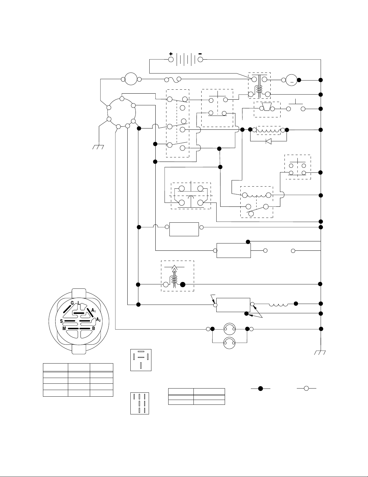
SCHEMATIC
AMMETER
BLACK
RED
B
G
L
(OPTIONAL)
A
WHITE
S
M
AI
A2
ORANGE
RED
FUSE
PTO (DISENGAGED)
RED
BLACK
BATTERY
RED
CG
F
H
B
E
A
D
SEAT SWITCH
(NOT OCCUPIED)
CLUTCH / BRAKE
(PEDAL UP)
SOLENOID
WHITE
RED
FBI BUZZER
ELECTRIC CLUTCH
BLACK
DIODE
STARTER
M
BLACK
FBI
SWITCH
BAG
INTERLOCK
BLACK
BLACK
IGNITION SWITCH
CIRCUITPOSITION
OFF
M+G+A1
B+A1RUN/LIGHT
B+A1RUN
B+S+A1START
WIRING INSULATED CLIPS
NOTE: IF WIRING INSULATED
CLIPS WERE REMOVED FOR
SERVICING OF UNIT, THEY
SHOULD BE REPLACED TO
PROPERLY SECURE YOUR
WIRING.
“MAKE”
NONE
A2+L
NONE
NONE
H
GROUNDING
CONNECTOR
BLUE
HOUR
METER
(OPTIONAL)
BLUE RED
CARBURATOR SOLENOID
RED
87
87A
8586
30
RELAY
FC
G
E
B
A
D
OFF
BLACK
FUEL
LINE
BROWN
PTO SWITCH
C+F,B+E,A+DON
BLACK
CHARGING SYSTEM OUTPUT
9 AMP DC @ 3600 RPM
HEADLIGHTS
CIRCUITPOSITION
C+G,B+H
85 86
IGNITION
UNIT
87
30
87A
RELAY
SPARK
PLUGS GAP
(2 PLUGS ON
TWIN CYL. ENGINES)
ALTERNATOR
REGULATOR
28 VOLTS AC @ 3600 RPM (REGULATOR DISCONNECTED)
BLACK
NON-REMOVABLE
CONNECTIONS
BLACK
REMOVABLE
CONNECTIONS
3
REPAIR PARTS
TRACTOR- -MODEL NO. 165H107RB (BA165H107RBD), PROD UCT 964 77 27-02
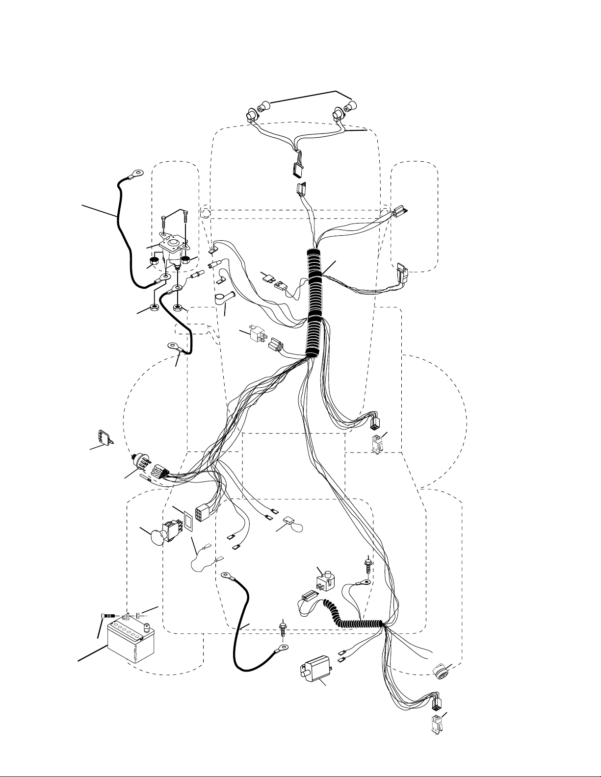
ELECTRICAL
22
21
24
33
30
27
43
27
25
41
27
27
40
26
42
81
16
51
50
48
27
2
1
28
52
66
29
66
58
59
16
4

REPAIR PARTS
TRACTOR- -MODEL NO. 165H107RB (BA165H107RBD), PROD UCT 964 77 27-02
ELECTRICAL
KEY PART
NO. NO. DESCRIPTION
1 532 16 34-65 Battery
2 874 76 04-12 Bolt Hex Hd 1/4-20 unc x 3/4
16 532 17 61-38 Switch Interlock
21 532 18 37-59 Harness Asm Light W/4152J
22 532 00 41-52 Bulb Light #1156
24 532 12 47-80 Cable Starter 6 Ga. 11" Red
25 532 16 59-87 Cable Battery Crd 56" Red
26 532 17 51-58 Fuse
27 873 51 04-00 Nut Keps Hex 1/4-20 unc
28 532 12 77-25 Cable Ground 6 Ga. 18" Black
29 532 12 13-05 Switch Plunger Normal N Gray
30 532 17 55-66 Switch Ignition
33 532 14 04-01 Key Ign
40 532 18 80-35 Harness Ign
41 871 11 04-08 Bolt Flk Fin Hex 1/4-20 unc x 1/2
42 532 13 15-63 Cover Terminal Red
43 532 17 88-61 Solenoid
48 532 14 08-44 Adapter Ammeter Rectangular
50 532 17 46-51 Switch PTO
51 532 14 04-05 Ring Retainer PTO
52 532 14 19-40 Protection Wire Loop
58 532 16 94-19 Buzzer Crd
59 532 18 03-79 Switch FBI CRD
66 817 49 06-08 Screw Thdrol 3/8-16 x 1/2 Ty-Tt
81 532 10 97-48 Relay Asm
NOTE: All component dimensions given in U.S. inches.
1 inch = 25.4 mm.
5
REPAIR PARTS
TRACTOR- -MODEL NO. 165H107RB (BA165H107RBD), PROD UCT 964 77 27-02
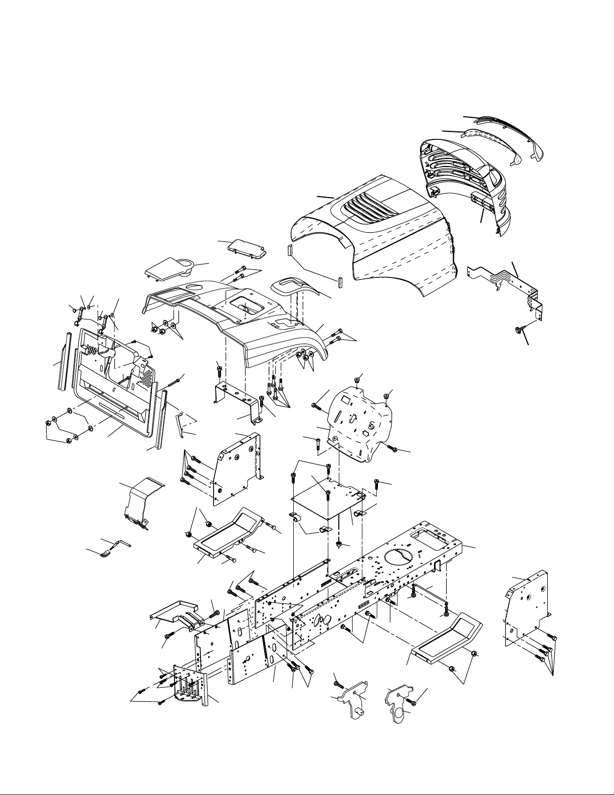
CHASSIS AND ENCLOSURES
29
212
17
28
256
39
166
266
187
189
188
186
187
188
171
189
26
190
25
171
165
209
24
18
89
30
24
26
25
209
5
5
173
172
185
198
179
170
175
209
265
164
207
209
31
184
208
26
33
3
11
10
209
209
162
2
209
209
35
24
26
163
209
15
209
9
209
3
209
8
8
26
24
6
16
145
37
209
35
205
38
37
34
205
38
1
13
208
26
chassis_Elite Value_CRD_6
69
6

REPAIR PARTS
TRACTOR- -MODEL NO. 165H107RB (BA165H107RBD), PROD UCT 964 77 27-02
CHASSIS AND ENCLOSURES
KEY PART
NO. NO. DESCRIPTION
1 532 17 46-20 Chassis Assembly
2 532 18 03-84 Drawbar
3 817 06 06-12 Screw 3/8-16 x .75 smqml Tap/R.Z
5 532 15 52-72 Bumper Hood/Dash
6 532 18 44-19 Saddle
8 532 12 64-71 Clip Insulator 13/32 Mtg. Hole
9 532 18 56-23 Dash
10 872 14 06-08 Bolt, Carriage 3/8-16 x 3/4
11 532 17 49-96 Panel, Dash, L.H.
13 532 17 52-55 Panel, Asm. Dash R.H.
15 874 18 05-12 Screw, Machine, Truss Head
5/16-18 unc x 3/4
16 873 51 05-00 Nut
17 532 18 65-80 Hood Assembly
18 532 12 69-38 Bumper Hood
24 874 78 06-16 Bolt
25 819 13 13-12 Washer 13/32 x 13/16 x 12 Ga.
26 873 80 06-00 Nut
28 532 18 35-52 Grille/Lens Asm
(Includes Nos. 29 & 212)
29 532 18 58-46 Lens, Grille
30 532 18 25-06 Fender
31 532 16 51-56 Bracket, Fender Support
33 532 18 25-07 Footrest, L.H.
34 532 18 25-08 Footrest, R.H.
35 872 11 06-06 Bolt
37 817 49 05-08 Screw Thdrol 5/16-18 x 1/2 TYT
38 532 18 17-48 Pivot Bracket Assembly
39 532 17 47-14 Bracket Pivot
69 532 14 24-32 Screw Hex Wsh Hi-Lo 1/4-1/2
89 532 18 13-60 Console CRD
KEY PART
NO. NO. DESCRIPTION
145 532 15 65-24 Rod Pivot Chassis/Hood
162 532 18 03-82 Bracket Exten Chassis Lh CRD
163 532 18 03-83 Bracket Exten Chassis Rh CRD
164 532 16 56-05 Support Battery CRD
165 532 18 13-56 Cover Battery CRD
166 532 17 18-75 Screw
170 532 17 88-62 Backplate Asm. CRD
171 872 14 06-20 Bolt Hex 3/8-16 x 2-1/2 Gr. 5
172 819 13 20-16 Washer 13/32 x 1-1/4 x 16 Ga.
173 873 51 06-00 Nut, Keps Hex 3/8-16 unc
175 532 18 82-03 Guard Door Rear CRD
179 532 18 82-02 Rod Pivot FBI CRD
184 532 17 46-62 Bracket Actuator Bagger CRD
185 532 18 11-01 Knob Rod Brake Parking
186 532 16 07-93 Latch Asm Mulch/Bagger
187 532 12 50-04 Nut Weld
188 819 06 12-16 Washer #10
189 810 07 10-00 Washer Lock #10
190 871 08 10-10 Screw Pan Hd Phillip 10-24 x 5/8
198 532 16 89-37 Nut Push
205 817 49 06-08 Screw
207 817 67 05-08 Screw 5/16-18 x 1/2
208 817 67 06-08 Screw Thdrol 3/8-16 x 1/2
209 817 00 06-12 Screw Hex Wsh Thdrol 3/8-16
212 532 18 35-50 Insert Lens Refl ective
256 532 18 13-61 Cover Fender Rack
265 532 18 57-04 Seal RH Side Bagger
266 532 18 57-03 Seal LH Side Bagger
NOTE: All component dimensions given in U.S. inches.
1 inch = 25.4 mm.
7
REPAIR PARTS
TRACTOR- -MODEL NO. 165H107RB (BA165H107RBD), PROD UCT 964 77 27-02
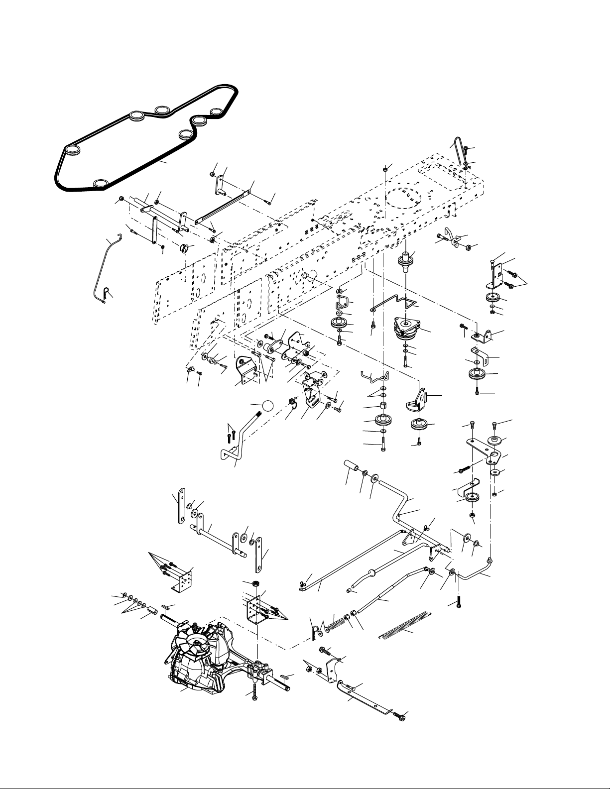
DRIVE
183
183
180
183
183
57
16
81
16
199
95
96
84
199
16
169
255
35
38
197
171
47
269
52
172
185
199
199
51
179
178
179
168
166
180
26
184
42
40
38
42
207
186
163
14
167
10
159
160
161
171
112
14
163
158
162
83
21
82
165
156
39
8
62
36
214
36
35
35
56
177
36
51
116
63
66
9
65
17
20
259
183
187
27
49
34
37
258
263
275
243
212
202
260
171
261
26
51
181
250
43
50
182
183
187
50
150
48
151
51
47
120
250
30
16
76
78
75
74
77
255
28
36
35
258
53
30
250
22
96
26
29
25
24
51
215
26
26
27
55
263
71
73
200
263
16
77
1
145
drive-hydro_CRD_Laser_13
8

REPAIR PARTS
TRACTOR- -MODEL NO. 165H107RB (BA165H107RBD), PROD UCT 964 77 27-02
DRIVE
KEY PART
NO. NO. DESCRIPTION
1 - - - - - - - Transaxle Hydro Gear 321-0510
(Order parts from transaxle manu-
facturer)
8 532 16 56-19 Rod, Shift Fender Adjust Lt
9 532 18 02-20 Clutch Elec.
10 876 02 04-16 Pin, Cotter 1/8 x 1
14 810 04 04-00 Washer, Lock Hvy Helical
16 873 80 05-00 Nut, Lock Hex w/Ins 5/16-18 unc
17 532 12 61-97 Washer 1 1/2 x 15/32 x 1/4
20 871 17 07-64 Bolt Hex 7/16-20 x 4 x Gr. 5
21 532 14 08-45 Knob
22 532 17 56-07 Rod, Brake
24 873 35 06-00 Nut
25 532 10 68-88 Spring, Rod, Brake
26 819 13 13-16 Washer 13/32 x 13/16 x 16 Ga.
27 876 02 04-12 Pin, Cotter 1/8 x 3/4
28 532 17 57-65 Rod, Parking Brake
29 532 07 16-73 Cap, Parking Brake
30 532 16 95-92 Bracket, Mfg. Transaxle
34 532 17 55-78 Shaft, Asm Pedal Foot CRD
35 532 12 01-83 Bearing, Nylon
36 819 21 16-16 Washer 21/32 x 1 x 16 Ga.
37 532 12 49-63 Pin, Roll 3/16 x 1"
38 532 16 59-36 Pulley Flat Composite 3.06"
39 532 17 39-37 Bolt
40 532 12 49-65 Spacer, Split 395 x 59 Bzp
42 819 13 13-12 Washer 13/32 x 13/16 x 12 Ga.
43 819 11 10-12 Washer 11/32 x 5/8 x 12 Ga
47 532 12 77-83 Pulley, Idler, V Groove Plasitc
48 532 15 44-07 Bellcrank Clutch Grnd Drv
49 532 12 32-05 Retainer, Belt Style Spring
50 872 11 06-12 Bolt Carr SH 3/8-16 x 1-1/2 Gr.5
51 873 80 06-00 Nut, Crownlock 3/8-16 unc
52 873 6805-00 Nut Crownlock 5/16-18
53 532 10 57-10 Link, Clutch 7.66
55 532 10 57-09 Spring, Return, Clutch
56 817 06 06-20 Screw 3/8-16 x 1-1/4
57 532 17 01-40 V-Belt Kev 112" 0650 CRD
62 532 12 48-72 Cover, Pedal
63 532 18 03-97 Pulley Engine
65 810 04 07-00 Washer
66 532 15 47-78 Keeper, Belt Engine F-Proof
71 532 16 91-83 Strap, Torque, Lh
73 532 16 91-82 Strap, Torque, Rh
74 532 13 70-57 Spacer, Split
75 532 12 17-49 Washer 25/32 x 1-1/4 x 16 Ga.
76 812 00 00-01 Ring, E
77 532 12 35-83 Key, Square
78 532 12 17-48 Washer 25/32 x 1-5/8 x 16 Ga.
81 532 17 00-06 Asm, Shaft
82 532 16 57-11 Spring, Torsion
83 819 17 12-16 Washer 17/32 x 3/4 x 16 Ga.
84 532 17 00-07 Link, Transaxle
95 532 17 00-15 Control Asm Bypass Hydro
KEY PART
NO. NO. DESCRIPTION
96 532 12 47-88 Spring, Retainer 1”
112 819 09 12-10 Washer 9/32 x 3/4 x 10 Ga.
116 872 14 06-08 Bolt RDHD Spnk 3/8-16 x 1
120 873 90 06-00 Nut Lock Flg. 3/8-16 unc
145 874 49 05-44 Bolt Hex FGHD 5/16-18 x Gr 5
150 532 16 58-50 Bushing, Bellcrank Grnd Dr
151 819 13 32-10 Washer 13/32 x 2 x 10 Ga.
156 532 16 60-02 Washer Srrted 5/16 ID x 1.125
158 532 16 55-89 Bracket Shift Mount
159 532 18 39-00 Hub Shift
160 532 16 98-45 Washer Nylon
161 872 14 04-06 Bolt Rdhd Sqnk 1/4-20 x 3/4 Gr 5
162 873 68 04-00 Nut Crownlock 1/4-20 unc
163 874 78 04-16 Bolt Hex Fin 1/4-20 unc x 1 Gr 5
165 532 16 56-23 Bracket Pivot Lever
166 817 49 05-10 Screw 5/16-18 x 5/8
167 532 16 55-88 Bracket Support Shift CRD
168 532 16 54-92 Bolt Shoulder 5/16-18 x .561
169 532 16 55-80 Plate Fastening Lt
171 817 49 06-08 Screw Thdrol 3/8-16 x 1/2 Ty-Tt
172 532 17 02-71 Shaft Asm Shifter Frt CRD
177 532 16 59-32 Keeper Flat Idler 3.06" CRD
178 532 16 59-33 Keeper Belt Idler 1.88" CRD
179 532 12 09-58 Washer Sintered
180 532 16 56-30 Pulley, Idler, Flat 1.88"CRD
181 532 18 02-11 Bracket Idler Ground Drive CRD
182 532 18 26-82 Keeper Belt 2.5" Od V-Idler CRD
183 532 18 60-07 Pulley V-Idler 2.50" Od CRD
184 817 49 06-44 Screw Hexwsh Thdrol
3/8-16 x 2-3/4
185 532 17 00-08 Link Shift
186 532 16 56-14 Hub Tapered Round CRD
187 817 58 05-20 Screw Thdrol 5/16-18 x 1.25
197 532 16 96-13 Nyliner Snap-In 5/8
199 532 16 96-12 Bolt Shoulder 5/16-18 unc
200 872 14 05-08 Bolt RDHD SQNK 5/16-18 x 1
202 872 11 06-14 Bolt Carr. Sh. 3/8-16 x 1-3/4 Gr. 5
207 532 16 98-45 Washer Nylon Rear
212 532 14 52-12 Nut Hex Flange Lock
214 532 17 56-09 Shaft Asm. Brake
215 532 17 56-52 Rod Brake Hydro
243 532 17 82-89 Bracket Anti-Rotate
250 817 06 06-12 Screw 3/8-16 x .75
255 532 17 56-08 Brace Shaft Brake Mtg.
258 532 17 80-62 Clip Retainer
259 532 18 02-12 Bracket Pulley
260 532 18 17-81 Bracket Idler Chassis
261 532 13 14-94 Pulley Idler Flat
263 817 00 06-12 Screw 3/8-16 x 3-4
269 532 18 24-02 Guard Muffl er OHV B & S RH
275 819 13 16-14 Washer 13/32 x 1 x 14 Ga.
NOTE: All component dimensions given in U.S. inches
1 inch = 25.4 mm
9

REPAIR PARTS
TRACTOR- -MODEL NO. 165H107RB (BA165H107RBD), PROD UCT 964 77 27-02
STEERING ASSEMBLY
38
12
39
1
41
42
37
37
36
44
51
91
43
29
15
steering_pl.lt_49
54
88
71
68
29
17
68
82
15
15
29
46
8
6
2
87
5
3
11
40
10
13
65
32
33
34
35
67
46
8
6
67
67
87
5
4
43
43
95
8
10

REPAIR PARTS
TRACTOR- -MODEL NO. 165H107RB (BA165H107RBD), PROD UCT 964 77 27-02
STEERING ASSEMBLY
KEY PART
NO. NO. DESCRIPTION
1 532 17 20-92 Steering Wheel
2 532 18 47-06 Axle Assembly
3 532 16 98-40 Spindle Assembly, L.H.
4 532 16 98-39 Spindle Assembly, R.H.
5 532 12 49-31 Bearing, Race, Thrust, Hardened
6 532 12 17-48 Washer 25/32 x 1-5/8 x 16 Ga.
8 812 00 00-29 Ring, Klip
10 532 17 51-21 Link, Drag
11 810 04 06-00 Washer, Lock
12 873 94 08-00 Nut Hex Jam Toplock 1/4-20 unf
13 532 13 65-18 Spacer Brg Axle Front
15 532 14 52-12 Nut, Hexfl ange Lock
17 532 18 06-41 Shaft Assembly, Steering
29 817 00 06-12 Screw, 3/8-16 x 3/4
32 532 17 18-88 Rod, Tie
33 819 11 12-16 Washer 11/32 x 3/4 x 16 Ga.
34 810 04 05-00 Washer Lock Hvy Hlcl Spr 5/16
35 873 54 05-00 Nut Crownlock 5/16-24 unf
36 532 15 50-99 Bushing, Steering
37 532 15 29-27 Screw TT #I0-32 x 5 x 3/8 Flange
38 532 17 20-93 Cap Wheel Steer
39 819 18 24-11 Washer 9/16 x 1-1/20 x 11 Ga.
40 873 54 06-00 Nut 3/8-24
41 532 15 99-45 Adaptor, Steering Wheel
42 532 16 96-33 Boot, Steering Dash P/L Mtl
43 532 12 17-49 Washer 25/32 x 1-1/4 x 16 Ga.
44 532 18 06-40 Extension Steering Non-Adjust
46 532 12 12-32 Cap, Spindle
51 873 54 04-00 Nut Crownlock 1/4-28
54 871 13 04-20 Bolt Hex 1/4-28 unf x 1 1/4
65 532 16 03-67 Spacer Brace Axle
67 872 11 06-18 Bolt Rdhd Sq 3/8-16 unc x 2-1/4
71 532 17 51-46 Steering Asm.
68 532 16 98-27 Brace Axle
82 532 16 98-35 Bracket Susp Chassis Front
87 532 17 39-66 Washer Flat .781 x 1-1/2 x .14
88 532 17 51-18 Bolt Shoulder 7/16-20 unc
91 532 17 55-53 Clip Steering
95 532 18 89-67 Washer Hardened
NOTE: All component dimensions given in U.S. inches.
1 inch = 25.4 mm.
11

REPAIR PARTS
TRACTOR- -MODEL NO. 165H107RB (BA165H107RBD), PROD UCT 964 77 27-02
SEAT ASSEMBLY
1
8
8
9
7
5
6
22
14
9
7
10
24
16
15
13
17
seat_lt.knob_10(CRD)
KEY PART
NO. NO. DESCRIPTION
12
11
2
5
4
3
KEY PART
NO. NO. DESCRIPTION
21
1 532 18 87-05 Seat
2 532 18 01-66 Bracket Pivot Fender
3 871 11 06-16 Bolt Fin Hex 3/8-16 unc x 1
4 819 13 16-10 Washer Flat 13/32 x 1 x 10 Ga.
5 532 14 50-06 Clip Push In Hinged
6 873 80 06-00 Nut Lock Hex 3/8-16 unc
7 532 12 41-81 Spring Seat Cprsn 2 250 Blk Zi
8 817 00 06-16 Screw 3/8-16 x 1-1/2
9 819 13 16-14 Washer 13/32 x 1 x 14 Ga.
10 532 18 01-86 Pan Pnt Seat (blk )
11 532 16 63-69 Knob Seat Adj Wingnut
12 532 12 12-46 Bracket Pnt Mounting Switch
13 532 12 12-48 Bushing Snap Blk Nyl 50 Id
14 872 05 04-12 Bolt Rdhd Sht Nk 1/4-20 x 1-1/2
15 532 13 43-00 Spacer Split
16 532 12 12-50 Spring Cprsn Plate SW 1.310 Ga.
17 532 12 39-76 Nut Lock 1/4 Lge Flg Gr. 5 Zinc
21 532 17 18-52 Bolt Shoulder 5/16-18 unc-2A
22 873 80 05-00 Nut Hex Lock w/Ins 5/16-18
24 819 17 19-12 Washer 17/32 x 1-3/16 x 12 Ga.
NOTE: All component dimensions given in U.S. inches.
1 inch = 25.4 mm
12

REPAIR PARTS
TRACTOR- -MODEL NO. 165H107RB (BA165H107RBD), PROD UCT 964 77 27-02
DECALS
8
4
3
3
7
14
21
2
12
1
KEY PART
NO. NO. DESCRIPTION
1 532 14 54-98 Decal Read Owner’s Manual Sym
2 532 18 95-04 Decal Hp Engine
3 532 18 96-91 Decal Hood
4 532 18 95-75 Decal Fender
5 532 18 04-35 Decal Rear Plate CRD Symbols
6 532 18 04-32 Decal 100 DBA/CE
7 532 18 26-21 Decal Bagger
8 532 18 96-98 Decal Steering Wheel
10 532 14 50-05 Decal Bat Dan/Poi P/L Sym Wpn
11 532 18 21-66 Decal Mower Cut Finger Symbol
12 532 15 97-37 Decal Brake/Clutch Symbol Lt
17
6
20
14
11
+
+
_
_
90N
MAX
150N
MAX
5
10
KEY PART
NO. NO. DESCRIPTION
14 532 15 97-36 Decal Chassis Hot Muffl er
17 532 14 08-37 Decal Saddle Brake Parking
20 532 16 69-60 Decal Bypass Fender CRD
21 532 16 62-86 Decal Hex Belt Sch
— 532 13 83-11 Decal Lift Handle
— 532 18 10-90 Pad Footrest RH
— 532 18 10-91 Pad Footrest LH
— 532 18 26-21 Decal Bagger Frame
— 532 18 51 69 Manual Operator's (Scand)
— 532 18 52-03 Manual Operator's (Euro)
— 532 18 94-04 Manual Parts
WHEELS & TIRES
1
2
6
5,8
KEY PART
NO. NO. DESCRIPTION
1 532 05 91-92 Cap Value Tire
2 532 06 51-39 Stem Value
3 532 10 62-22 Tire F Ts 15 x 6 0 - 6 Service
4,10
7
3,9
11
4 532 05 99-04 Tube Inner Front #35060
5 532 18 33-37 Rim Asm 6" front Service
6 532 12 49-57 Fitting Grease
7 532 12 49-59 Bearing Flange
8 532 18 33-38 Rim Asm 8" rear Service
9 532 12 20-82 Tire R Ts 20 x 10-8 Service
10 532 12 49-26 Tube Rear 9 5 X 8 Service
11 532 17 50-39 Cap Axle Blk 1 50 x 1 00
- - 144334 Sealant, Tire (10 oz. tube)
NOTE: All component dimensions given in U.S. inches
1 inch = 25.4 mm
wheel_1
13

REPAIR PARTS
TRACTOR- -MODEL NO. 165H107RB (BA165H107RBD), PROD UCT 964 77 27-02
ENGINE
32
14
3
72
81
78
13
4
2
1
78
38
44
46
31
33
37
33
45
29
23
OPTIONAL EQUIPMENT
Spark Arrester
engine-bs.1cyl_48
14

REPAIR PARTS
TRACTOR- -MODEL NO. 165H107RB (BA165H107RBD), PROD UCT 964 77 27-02
ENGINE
KEY PART
NO. NO. DESCRIPTION
1 532 17 05-51 Control Throt/Ck
2 817 72 04-08 Screw Hex Thd Cut 1/4-20 x 1/2
3 - - - - - - - - Engine B&S Model 31G777
(Order parts from engine manufacturer)
4 532 13 73-52 Muffl er
13 532 16 52-91 Gasket Muffl er
14 532 14 84-56 Tube Drain Oil Easy
23 532 16 98-37 Shield Brn/Dbr Guard
25 532 18 09-45 Control Choke
26 873 92 06-00 Nut Keps 3/8-24 unf
29 532 13 71-80 Kit Spark Arrestor (Flat Scrn)
31 532 18 55-34 Tank Fuel 2.00
32 532 14 05-27 Cap Asm Fuel W/sym Vented
33 532 12 34-87 Clamp Hose Blk
37 532 13 70-40 Line Fuel
38 532 18 16-54 Plug Drain Oil Easy
44 817 67 04-12 Screw Hexwsh thdrol 1/4-20 x 3/4
45 817 00 06-12 Screw Hexwsh Thdr 3/8-16 x 3/4
46 819 09 14-16 Washer 9/32 x 7/8 x 16 Ga.
62 810 04 05-00 Washer, Lock Hvy. Hlcl Spr 5/16
72 532 18 39-06 Screw Socket Head 5/16-18 x 1
78 817 06 06-20 Screw 3/8-16 x 1/4
81 873 51 04-00 Nut Keps Hex 1/4-20 unc
NOTE: All component dimensions given in U.S. inches
1 inch = 25.4 mm
15

REPAIR PARTS
TRACTOR- -MODEL NO. 165H107RB (BA165H107RBD), PROD UCT 964 77 27-02
MOWER LIFT
37
38
29
40
41
36
28
13
27
25
24
23
7
8
5
49
30
50
1
3
13
13
11
19
31
32
31
32
4
12
19
26
6
2
13
20
15
6
5
4
20
18
17
16
20
20
15
lift-rh.1pc.stlt_10
16

REPAIR PARTS
TRACTOR- -MODEL NO. 165H107RB (BA165H107RBD), PROD UCT 964 77 27-02
MOWER LIFT
KEY PART
NO. NO. DESCRIPTION
1 532 15 94-61 Washer Asm Inner Spring W/Plunger
2 532 15 94-76 Shaft Asm. Lift
3 532 17 89-81 Pin Groove
4 812 00 00-02 E Ring #5133-62
5 819 21 16-21 Washer 21/32 x 1 x 21 Ga.
6 532 12 01-83 Bearing Nylong
7 532 12 56-31 Grip Handle Fluted
8 532 12 45-26 Button Plunger Black
11 532 16 58-29 Link Asm Lift L.H.
12 532 16 58-31 Link Asm Lift R.H.
13 532 12 46-70 Retainer Spring
15 532 17 32-88 Link Front
16 873 35 08-00 Nut Jam Hex 1/2-13 unc
17 532 17 56-89 Trunnion Blk Zinc
18 873 80 08-00 Nut Lock w/wsh 1/2-13 unc
19 532 13 98-68 Arm Suspension Mower
20 532 16 35-52 Retainer Spring
23 532 11 08-07 Nut Special
24 819 13 10-16 Washer 13/32 x 5/8 x 16 Ga.
25 532 12 48-74 Spring 2-1/8"
26 532 16 94-84 Retainer Clip
27 532 12 69-71 Rod Adj Lift Zinc 7.49 Wrk Lg
28 873 35 06-00 Nut Hex Jam 3/8-16 unc
29 532 13 80-57 Knob Inf 3/8-16 unc Blk w/sym
30 532 15 02-33 Trunnion Infi n Height
31 532 16 98-65 Bearing, Pvt. Lift.
32 873 54 06-00 Nut Crownlock 3/8-24
36 532 15 50-97 Pointer Height Indicator
37 532 12 39-35 Plug Hole Blk 1.485/1.515 Dia
38 817 06 05-16 Screw 5/16-18 x 1
40 819 11 24-10 Washer 11/32 x 1-1/2 x 10 Ga.
41 532 12 39-34 Scale Ind Height Blk
49 532 14 52-12 Nut hex Flange Lock
50 532 11 04-52 Nut Push Phos & Oil
NOTE: All component dimensions given in U.S. inches
1 inch = 25.4 mm
17

REPAIR PARTS
34
21
117
119
116
118
2
21
34
116
117
119
2
118
TRACTOR- -MODEL NO. 165H107RB (BA165H107RBD), PROD UCT 964 77 27-02
MOWER
116
32
117
68
119
124
33
31
23
32
40
124
41
36
21
41
36
84
18
26
2
25
21
118
21
35
21
119
117
116
40
164
38
55
164
36
32
36
5
19
21
36
46
3
21
6
4
1
41
35
36
22
44
33
32
31
30
27
39
30
28
61
30
21
24
21
30
118
107cm_deck-elect.(CRD)_1
21
2
2
131
124
11
161
130
162
13
46
2
15
46
2
9
8
20
14
69
163
16
162
9
45
18

REPAIR PARTS
TRACTOR- -MODEL NO. 165H107RB (BA165H107RBD), PROD UCT 964 77 27-02
MOWER
KEY PART
NO. NO. DESCRIPTION
1 532 16 91-60 Housing Asm. Mower 107 CRD
2 872 14 05-06 Bolt Rdhd Sqnk 5/16-18 unc x 3/4
3 532 16 55-69 Bracket Asm. S-Bar Chass 92 CRD
4 532 16 91-67 Bracket Bar Sway Deck 107 CRD
5 532 12 46-70 Retainer Spring
6 532 16 55-57 Bar Sway 92 CRD
8 532 18 17-12 Bolt 3/8-24 x 1.25 Gr. 8 Patched
9 810 03 06-00 Washer Lock Hvy 3/8 Unplated
11 532 18 05-83 Blade 3-1 Lh 107 CRD
13 532 13 76-45 Shaft Asm. W/Lower Bearing
14 532 12 87-74 Housing Mandrel Vented (Machd)
15 532 11 04-85 Bearing Ball Mandrel
16 532 18 05-84 Blade 3-1 Rh 107 CRD
18 872 11 06-06 Bolt RDHD SQNK 38/-16 x 3/4 Gr. 5
19 532 13 28-27 Bolt Shoulder 5/16-18 Thd Form
20 532 18 17-13 Bolt 3/8-24 x 1.25 Gr. 8 Ptch Lhthd
21 873 68 05-00 Nut Crown Lock 5/16-18
22 532 16 91-65 Bracket Idler Sprt RR 107 CRD
23 532 16 91-66 Bracket Idler Sprt RF 107 CRD
24 532 16 91-70 Bracket Suspension LF 107 CRD
25 532 16 91-71 Bracket Suspension RF 107 CRD
26 532 16 52-37 Brace Support Susp Frt CRD
27 532 16 91-72 Bracket Asm. Susp RR 107 CRD
28 532 16 91-68 Bracket Asm. Susp LR 107 CRD
30 532 17 39-84 Screw Thd Rolling D.D. PT
31 532 18 76-90 Washer Spacer Mower Vented
32 532 17 57-07 Mandrel Pulleys
33 532 17 83-42 Nut Flg Top Lock
34 532 17 95-09 Bracket Gauge Wheel Lf 107 CRD
35 532 17 62-92 Bracket Gauge Wheel Rf 107 CRD
36 532 14 67-63 Pulley Idler V-Groove Dim 4.25
KEY PART
NO. NO. DESCRIPTION
38 532 16 98-51 Spacer Hub Arm Idler 107 CRD
39 872 11 06-22 Bolt Rdhd 3/8-16 unc x 2-3/4 Gr. 5
40 873 90 06-00 Nut Lock 3/8-16 unc
44 532 17 55-38 Cover Mandrel Lh 107 CRD
45 532 17 55-39 Cover Mandrel Rh 107 CRD
46 532 13 77-29 Screw Thd Roll 1/4-20 x 5/8
55 532 16 98-49 Arm Idler 107 CRD
61 532 17 51-59 Spring Tension Belt
68 532 16 91-78 Hex-Belt 107 Mower
69 532 16 54-82 Shaft Asm W/Lwr Brg Rh Thd CRD
84 532 15 60-85 Keeper Belt Idler
116 532 18 42-19 Bolt Shoulder
117 532 13 39-57 Wheel Gauge Donut Wide
118 873 93 06-00 Nut Centerlock 3/8-16 unc
119 819 12 14-14 Washer 3/8 x 7/8 x 14 Ga.
124 872 11 06-12 Bolt Carr Sh 3/8-16 x 1-1/2 Gr. 5
130 872 11 05-06 Bolt Rdhdsqnk 5/16-18 unc x 3/4
131 532 16 56-61 Chute Bagger CRD 92 cm
161 532 18 04-24 Blade Cross LH 107
162 532 18 08-78 Adapter Weldnut Blade 107
163 532 18 04-25 Blade Cross Rh 107
164 532 12 49-37 Bearing
-- 532 18 18-57 Mandrel Assembly (Includes Housing, Shaft and Shaft Hardware Only
- Pulley Not Included)
-- 532 18 18-58 Mandrel Asm CRD Lh Threads SVC
-- 532 18 17-70 Replacement Mower Complete
-- 532 18 18-57 Mandrel Asm CRD Service
NOTE: All component dimensions given in U.S. inches
1 inch = 25.4 mm
19

REPAIR PARTS
TRACTOR- -MODEL NO. 165H107RB (BA165H107RBD), PROD UCT 964 77 27-02
BAGGER
39
16
28
5
5
4
8
1
32
24
31
6
4
6
43
23
22
3
7
3
13
11
16
19
9
7
7
25
7
17
12
17
38
41
19
37
36
14
2
9
2
19
3
3
14
36
22
20
41
37
2
38
16
10
13
11
16
Bagger Asy (CRD)_6
3
26
21
20

REPAIR PARTS
TRACTOR- -MODEL NO. 165H107RB (BA165H107RBD), PROD UCT 964 77 27-02
BAGGER
KEY PART
NO. NO. DESCRIPTION
1 532 16 52-49 Tube Handle Bagger CRD
2 872 14 04-16 Bolt Carriage 1/4-20 X 2.0 Gr. 5
3 532 12 39-76 Nut Lock 1/4 Lge Flg Gr. 5 Zinc
4 532 16 99-16 Handle Bagger w/Lvrs Gr. 5 Zinc
5 874 98 10-24 Screw Pan Head #10-24 x 1.50 Blk
6 874 98 10-32 Screw Pan Hd
7 873 40 10-00 Nut Wiz Lock Hex Serr/Hd #10-24
8 532 18 25-14 Cover Bagger
9 872 14 04-18 Bolt Carriage 1/4-20 x 2.25d x Gr. 5
10 532 18 12-82 Tube Support Bagger CRD
11 532 16 57-19 Bracket Support Upper Bag CRD
12 532 18 88-48 Bracket Pivot LH
13 872 11 06-06 Bolt Rdhd Sht Sqnk 3/8-16 x 3/4
14 874 52 06-36 Bolt Hex 3/8-16 x 2-1/4 Gr. 5
16 873 90 06-00 Nut Lock Flg 3/8-16 Unc
17 872 14 05-06 Bolt Rdhd Sht Sqnk 5/16-18 unc x 3/4
18 819 11 12-16 Washer 11/32 x 3/4 x 16
19 873 90 05-00 Nut Lock Hex Flange 5/16-18
20 532 18 88-47 Bracket Pivot RH
21 532 18 08-80 Bag Asm CRD
22 532 16 57-81 Bracket Side Bagger CRD
23 532 16 57-82 Tube Upper Bagger CRD
24 532 16 57-83 Tube Pivot Bagger CRD
25 532 18 01-24 Tube Front Bagger CRD
26 532 16 57-85 Tube Lower Bagger CRD
28 532 16 57-87 Grip Handle Black
31 532 16 94-84 Retainer
32 532 12 68-75 Rivet Rd Hd Drilled 3/8 Dia
36 819 13 20-16 Washer 13/32 x 1-1/4 x 16 Ga.
37 532 17 54-01 Plug Support Bagger CRD
38 872 01 05-20 Bolt 5/16-18 x 2-1/2
39 532 18 09-85 Seal
41 532 16 96-83 Bracket Vert Adj Bagger CRD
42 873 80 05-00 Nut Lock Hex W/Ins 5/16-18 unc
43 532 17 40-83 Plug Tubing end
NOTE: All component dimensions given in U.S. inches
1 inch = 25.4 mm
21

SERVICE NOTES
22

LIMITED WARRANTY
The Manufacturer warrants to the original consumer purchaser that this product as manufactured is free from defects in materials and work man ship. For a period of one (1) year from date of purchase by the original consumer purchaser, we will repair or
replace, at our option, without charge for parts or labor incurred in replacing parts, any part which we fi nd to be defective due
to materials or workmanship. This Warranty is subject to the following limitations and exclusions.
1. This warranty does not apply to the engine. Please contact your nearest dealer where they will send the machine to the
engine manufacturer.
2. Transportation charges for the movement of any power equipment unit or attachment are the responsibility of the pur chaser. Transportation charges for any parts submitted for replacement under this warranty must be paid by the purchaser
unless such return is requested by your dealer.
3. Battery Warranty: On products equipped with a Battery, we will replace, without charge to you, any battery which we fi nd
to be defective in manufacture, during the fi rst ninety (90) days of ownership. After ninety (90) days, we will exchange the
Battery, charging you 1/12 of the price of a new Battery for each full month from the date of the original sale. Battery must
be maintained in accordance with the instructions furnished.
4. The Warranty period for any products used for rental or commercial purposes is limited to 90 days from the date of original
purchase.
5. This Warranty applies only to products which have been properly assembled, adjusted, operated, and maintained in ac cor dance with the instructions furnished. This Warranty does not apply to any product which has been subjected to alteration,
misuse, abuse, improper assembly or installation, delivery damage, or to normal wear of the product.
6. Exclusions: Excluded from this Warranty are belts, blades, blade adapters, normal wear, normal adjustments, stan dard
hardware and normal maintenance.
7. In case of any problem within the boundaries of this warranty, contact the nearest department store, indicate the model
number, serial number and the date of purchase of your machine. This warranty does not apply to accidental damages. All
implicit warranties are limited to the same time frames. Or contact:
E.M. Services
54 Rue Lambrechts
92400 Courbevoie
France
Telephone: (1) 46678078
Fax: (1) 46678095
THIS WARRANTY DOES NOT APPLY TO INCIDENTAL OR CONSEQUENTIAL DAMAGES. ANY IMPLIED WAR RAN TIES
ARE LIMITED TO THE SAME TIME PERIODS STATED HEREIN.
23

Electrolux Outdoor Products Service Con tacts
BELGIQUE/BELGIË
Electrolux Outdoor Products
Tel: 02 363 0311, Fax: 02 363 0391
CESKÁ REPUBLIKA
Electrolux, spol. S.r.o., oz Electrolux Outdoor Products,
Na Krecku 365 Praha 10 - Horn
Tel: 02/7487 0164, Info-linka: 0800/110 220
Internet: www.partner-fl ymo.cz E-mail: info@husqvarna.cz
DANMARK
Electrolux Outdoor Products, Flymo/Partner A/S,
Lundtoftegaardsvej 93A, DK 2800 Kgs.Lyngby
Tel: 45 87 75 77, Fax: 45 93 33 08 www.fl ymo-partner.dk
DEUTSCHLAND
Electrolux Outdoor Products
Tel: 097 21 7640, Fax: 097 21 764202
ESTONIA
Electrolux Estonia Ltd (Electrolux Eesti AS)
Tel: (372) 6650010
FRANCE
Electrolux Outdoor Products
Tel 01 46 67 8141, Fax 01 43 34 2491
FINLAND SUOMI
Electrolux Outdoor Products Finland
Tel: 00 39611, Fax: 00 39 612632
ITALIA
McCulloch Italiana s.r.l. - Via Como 72, 23868 Valmadrera
(LECCO) - ITALIA, Tel: 800 017829, Fax: 0341 581671
IRELAND
Electrolux Outdoor Products
Tel: 01 4565222, Fax: 01 4568551
MAGYARORSZÁG
Electrolux Lehel Kft
Tel: 00 36 1 251 41 47
NORGE
Electrolux Outdoor Products
Tel: 69 10 47 90
NEDERLAND
Electrolux Outdoor Products BV
Tel: 0172-468322, Fax: 0172-468219
ÖSTERREICH
HUSQVARNA Zentralwerksttte, Industriezeile 36, 4020 LINZ,
Tel: 0732 770101-60, Fax: 0732 795922
POLSKA
Electrolux Poland Sp. z.o.o. Husqvarna, 01-612 Warszawa
Myslowicka 10/2
Tel:- (22) 8332949
SLOVENIJA
HUSQVARNA-Ges.m.b.H. Nfg. KG, Industriezeile 36, 4020 LINZ,
Tel: 0732 77 01 01-0, Fax: 0732 77 01 01.40
Internet: www.husqvarna.at E-mail: offi ce@husqvarna.co.at
SLOVENSKA
Electrolux Slovakia s.r.o., Borova Sihot 211, 033 01 Lipt. Hradok
Tel: 044 522 14 19, Fax: 044 522 14 18, www.fl ymo-partner.sk
SCHWEIZ/SUISSE/SUIZZERA
Electrolux Outdoor Products
Tel 062 889 93 50 / 889 94 25, Fax 062 889 93 60 / 889 94 35
SVERIGE
Electrolux Outdoor Products, Sverige
Tel: 036 û 14 67 00, Fax: 036 û 14 60 70
UNITED KINGDOM
Electrolux Outdoor Products, United Kingdom
Tel: 01325 300303, Fax: 01325 310339
í Mecholupy
www.electrolux.com/mcculloch
 Loading...