

Page 1
SENSOR INSERTION TOOL
CONTENTS
1 - SPI Mag Sensor
2 - Long threaded retaining rods
1 - Converter (M Series, L Series or ABB)
1 - Calibration Certicate
1 - SPI Mag Installation, Operation
and Maintenance Manual
1 - Converter Installation, Operation
and Maintenance Manual
SERIAL NUMBERS
SAFETY WARNINGS
!
!
!
!
!
2 - 3/4” reversible ratchet
wrenches
1 - Pipe thread sealant
1 - Compression Seal Assembly
4 - Hex nuts (3/8”)
2 - Locking cotter pins
1 - Power cord (8’, 115 VAC)
CONTACT INFORMATION
Copyright © 1997-2013 McCrometer, Inc. All printed material should not be changed or altered without permission of
McCrometer. Any published technical data and instructions are subject to change without notice. Contact your McCrometer
representative for current technical data and instructions. FPI-Mag™ is a trademark of McCrometer, Inc.
www.mccrometer.com
3255 WEST STETSON AVENUE • HEMET, CALIFORNIA 92545 USA
TEL: 951-652-6811 • 800-220-2279 • FAX: 951-652-3078 Printed In The U.S.A. Lit. 30120-66, Rev. 1.2 / 8-18-17
1
2
3
4
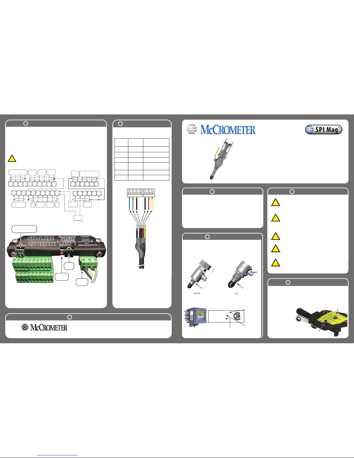
282L WIRING DIAGRAM
15
16
WARNING! Incorrect installation or removal of SPI
Mag meters can result in serious injury or death. Read
the instructions in this manual on the proper procedures
carefully.
WARNING! Never enter a conned space without
testing the air at the top, middle and bottom of the
space. The air may be toxic, oxygen decient or explosive.
Do not trust your senses to determine if the air is safe. You
cannot see or smell many toxic gases.
WARNING! Never enter a conned space without the
proper safety equipment. You may need a respirator, gas
detector, tripod lifeline and other safety equipment.
WARNING! Never enter a conned space without
standby/rescue personnel within earshot. Standby/
rescue personnel must know what action to take in case
of emergency.
WARNING! Carefully read all safety warning tags
attached to the meter.
Verify the system serial numbers on both the sensor and converter
match to ensure a properly calibrated system.
The Meter Serial Number is etched onto the sensor and can also be
located on a tag near the end of the sensor cable
The tag on the side of the converter has the Converter Model Number,
the Converter Serial Number and the Meter Serial Number.
All electrical cables enter the converter through compression ttings located on the side
of the converter. Ensure that all compression glands are properly tightened and all unused
ttings are plugged so the case remains sealed.
All connections are made on the terminal board. To access the terminal board, loosen the
four screws on the back of the converter to remove the rear cover.
TERMINAL BOARD (M-SERIES CONVERTER)
!
CAUTION! Always disconnect the power cord before attempting any
electrical connections.
14
Converter
Model Number
Meter Serial Number
Converter
Serial Number
Converter Model: 880003xxx
Converter SN: E12-34567
Meter Model: FPI 395L
Meter SN: MI12-0448
http://www.mccrometer.com
USC
®
Meter Serial Number Meter Serial Number
1 2 3 4 5 6 7 8 9
10
11 12 13 14 15 16 17 18 19 20
E1 E2 C SC + - B A + -
ELECTRODE INPUT RS485 4-20mA
-ECECE+SCB2B1SC
OUT2OUT124VCOILS 24V
21 22 23 24 25 26
27 28 29 30 31 32
OUT 3
E C
- +
INP2
E C
OUT 4
SC
- +
4..20mA
CTS RDTDSG
RS 232
Model 282L
Single Prole Insertion
Electromagnetic Flow Meter
Quick Start Guide
30120-66 Rev. 1.2
August 18, 2017
McCrometer recommends using a sensor insertion tool (P/N 75031) to
help with inserting the sensor and to avoid any damage to the sensor.
Place the proling
insertion tool over
the captive nuts and
lock it into place with
spring locks located
on the bottom of
the tool. Using the
provided wrench
rotate the high gear
shaft clockwise until
the bottom of the
sensor reaches the far
wall of the pipe.
Low Gear Shaft
High Gear Shaft
3/8” Insertion Tool (Part Number 75031) for
TSL < 72” and pressure < 200 psi
Terminal Block Assignments
Terminal Wire Color Connected To
#1 Blue Sensing electrode
#2 White Sensing electrode
#3 Black Reference ground
#11 Black
Magnet shield /
overall cable shield
#12 Red Coil
#13 Yellow Coil
Cable Diameter:
Single Cable (36002): 0.250”
DIP switch for block
levels enabling
Power
supply
Signaling
LED
IF2
socket
BLUE
WHITE
BLACK
BLACK
p/n 17177 Rev. 1.0 unreleased
YELLOW
RED
1 2 3 4 19 20 21
Note: M-Series wiring diagram is used in this
example. Additional wiring diagrams can
be found in the converter IOM or inside the
converter cover.
Page 2
RAW WATER SENSOR POSITION
The operation position for raw waste water and sludge is at sensor
location 0.00 to prevent debris from collecting on the sensor and
aecting velocity readings. To position the sensor at this location
follow the instructions below:
Calculate distance A by subtracting the pipe wall thickness
(WT) and ¾” from length C (Tube Length).
A = C - WT - ¾”
Using the captive nuts, position the top edge of the tube cap so
that its distance from the OD of the pipe is equal to “distance A”
calculated above. See diagram.
12
INSERTING THE SENSOR
!
WARNING! The compression seal/sensor assembly may be under
pressure. Serious injury may result if proper procedures are not
followed. Do not attempt to install the sensor without the retaining rods
fully assembled.
Ensure the compression seal is only hand tightened.
Barely crack open the valve and tighten the compression seal as required to minimize
leaks. A towel draped around the compression seal can reduce spray if necessary.
Open the valve completely. Failure to open the valve completely will cause the valve to
scrape the sensor during insertion and may result in permanent damage to the sensor.
Insert the sensor into the pipe by simultaneously
rotating clockwise the two captive nuts on the
top plate for the 2” sensor, and the single captive
nut on the 1” sensor. For the two captive nuts
on the 2” sensor use the two ratchet wrenches
provided. It is recommended that the Sensor
Insertion Tool be used to rotate the captive
nuts on the 2” sensor to ensure the top plate
compresses evenly.
IMPORTANT: If the captive
nuts are not tightened
simultaneously, the top
plate will become crooked
and cause the sensor to
be inser ted at an angle
and may cause permanent
damage.
i
11
CLEAN WATER SENSOR POSITION
13
If the ow is clean water, the sensor can be placed at 1/8 of the
inside diameter. To position the sensor at 1/8 of the ID, follow the
instructions below:
• Measure the tube from the top of the cap to the end of the
sensor to nd tube length (TL).
• Calculate (1/8 D): 1/8 D = 0.125 x Pipe ID
• Add wall thickness( WT) to 1/8 D.
• Calculate distance A: A = TL - (1/8 D + WT)
Using the captive nuts,
position the top edge of the
tube cap so that its distance
from the OD of the pipe is
equal to “distance A” calculated
above. See diagram.
If the ow is clean water, the sensor can be left at the 1/8D
position. Do not leave the sensor in this position for raw
waste water because debris could collect on the sensor and
aect the velocity readings. In waste water applications,
position the sensor at location 0.00.
0.00 Position
FULL PIPE SENSORS
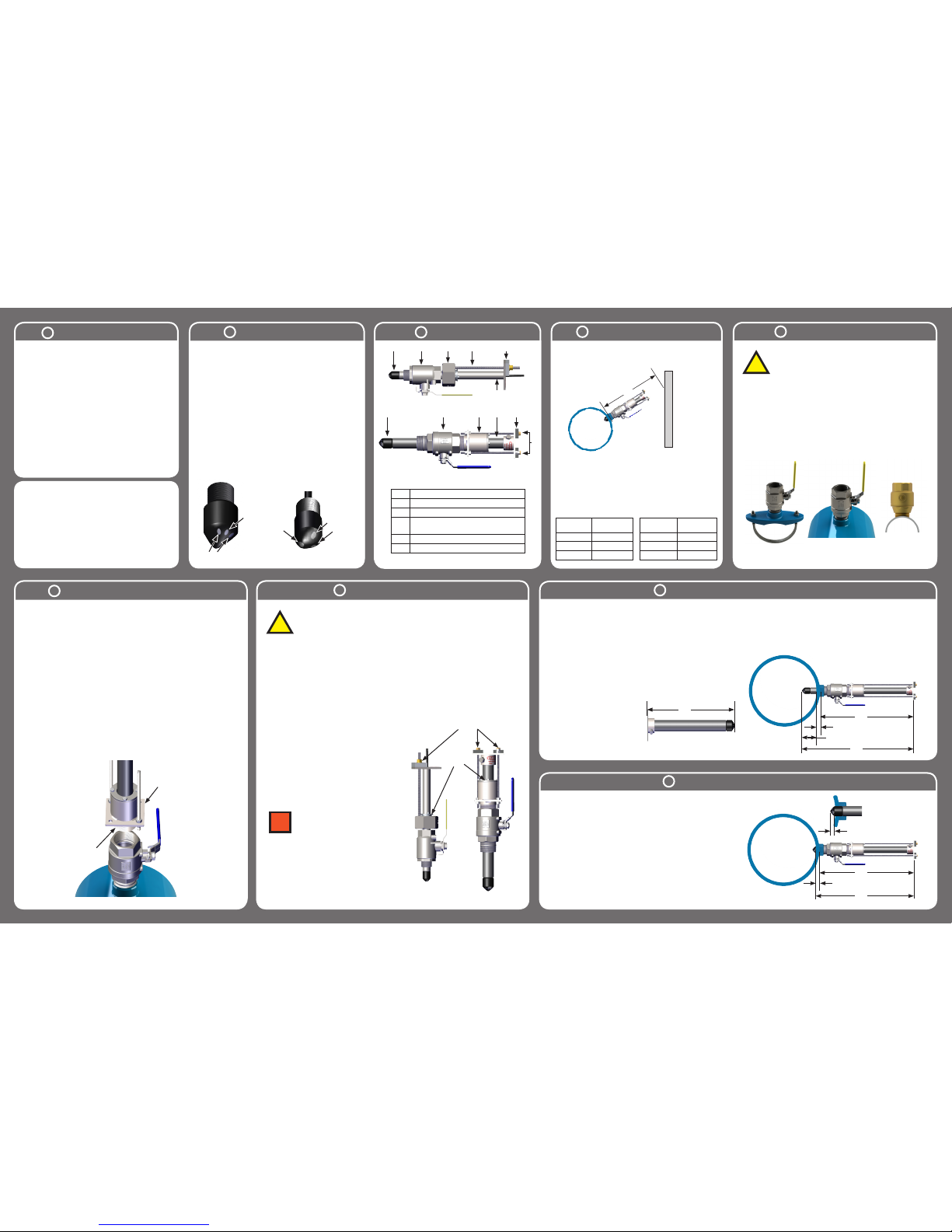
6
PARTS DIAGRAM
7
NOTE: Valves are optional or supplied by user.
1 Sensor Assembly
2 Bronze Ball Valve
3 Compression Seal Assembly
4
1" Insertion Tube with cap
2" Insertion Tube without cap
5 Insertion Tube Cap
6 3/8" SS Long Threaded Rod
Item No. Part Name
1 2 543
6
282L 1" Sensor
SENSOR ASSEMBLY INSTALLATION
The sensor assembly uses a compression seal, which keeps the sensor
watertight when the pipe is under pressure. Care must be taken when
installing the sensor, to avoid leaks.
Visually inspect all elements of the installation to ensure they are structurally
sound and of high quality materials, including all welds, couplings and
nipples.
Put a generous amount of the supplied pipe sealant on the compression
seal threads. Teon tape may also be used. NOTE: If pipe sealant gets on
the sensor electrodes the velocity signal may be lost.
Place the compression seal threads over the pipe valve. Turn the entire
sensor assembly clockwise to secure the assembly to the valve.
The seal is secure when a large amount of force is required to turn the
assembly. Line up the arrow (on the top plate) with the direction of the ow.
10
PIPE VALVE INSTALLATION
Install a 2” (50mm) full port valve or corporation stop with a 2”
(50mm) NPT female pipe thread output for the 2” sensor, or a
1” (25mm) full port valve or corporation stop with a 1” (25mm)
NPT female pipe thread output for the 1” sensor.. Follow any and
all installation instructions provided for the valve that you have
chosen. The valve or corporation stop can be installed onto a
welded coupling or pipe saddle
!
WARNING! Pressurized pipes should only be hot
tapped, cut, or drilled by qualied personnel
using high quality saddles, valves and stainless
steel nipples. If possible, depressurize the pipe
before attempting any installation.
9
SENSOR CLEARANCE
8
1. the height from the outer pipe wall to the
top of the installation valve
2. the length of the meter (see table)
3. additional 9” of working space
FLOW CALCULATION
5
The full pipe sensor makes use of Faraday’s Law of
Electromagnetic Induction to measure water velocity.
Faraday’s Law states: A conductor, moving through a
magnetic eld, produces a voltage.
Because water is a conductor, water moving through a
magnetic eld produces a voltage. The magnitude of
the voltage is directly proportional to the velocity of
the water. The sensor generates an electromagnetic
eld, creating a voltage in the water. The two velocity
electrodes, along with the ground electrode measure
this voltage. A faster water velocity produces a higher
voltage. By accurately measuring this voltage, the
velocity is determined.
Distance H is estimated by adding three measurements:
Insertion
Tube Length
Overall Sensor
Length
Insertion
Tube Length
Overall Sensor
Length
12” 18.25” 18” 24.25”
24” 30.25” 24” 30.25”
36” 42.25” 30” 36.25”
1” 282L 2” 282L
Pipe Saddle
With Ball Valve
Welded Pipe Nipple
With Ball Valve
Corporation
Stop
Velocity
Electrodes
Ground
Button
2” Sensor
1” Sensor
Velocity
Electrodes
Ground
Button
282L 2" Sensor
5321
6
4
The sensor will protrude from the pipe when
installed requiring sucient clearance from any
obstruction.
Obstruction
H
Compression
Seal Threads
Bottom Plate Compression
Seal Assembly
Compression
Seal
Captive Nuts
TL
Tube Length (TL)
1/8 D
TL
A
WT
1/8 D Position
C
A
WT
3/4”
If the engineering design for this installation
requires that ow in the line be proled, please
refer to the SPI Mag Proling Guides.
SPI Mag 1” Proling Guide: Lit# 24510-58
SPI Mag 2” Proling Guide: Lit# 24510-59
The Proling Guides can be downloaded at:
www.mccrometer.com/Library
To calculate the ow, two things are needed: The
cross-sectional area of the pipe and the average
velocity.
Cross-sectional area is found using the inside
diameter of the pipe. Average velocity is
found using the sensed velocity (measured by
the sensor). A site calibration is performed to
determine the velocity prole. This allows the
ow meter to calculate the average velocity from
the sensed velocity.
Flow is calculated by using the Continuity
Equation: Flow = Average Velocity x Area
 Loading...