

McCormick cx75, cx85, cx95, cx105 Service manual
INTERSTATER
Assembly Instruction
Manual
Published 07-05 Part No. 02982245
McCORMICK CX75 - CX85 - CX95 -CX105
(Cab - 2 & 4 WD)
INTERSTATER
Tractors equipped with additional options, special equipment, tractor manufacturer modifications, new tractor models, or Customer alterations may prevent this Mount Kit from
being properly mounted to the tractor. Alamo Group is not responsible for modifications to
the MountKit to accommodate these differences.
ALAMO INDUSTRIAL
1502 E. Walnut
Seguin, Texas 78155
210-379-1480
© 2005 Alamo Group Inc.


TO THE OWNER/OPERATOR/DEALER
All implements with moving parts are potentially hazardous. There is no substitute for a cautious, safe-minded operator
who recognizes the potential hazards and follows reasonable safety practices. The manufacturer has designed this
implement to be used with all its safety equipment properly attached to minimize the chance of accidents.
BEFORE YOU START!! Read the safety messages on the implement and shown in your manual. Observe
the rules of safety and common sense!
WARRANTY INFORMATION:
Read and understand the complete Warranty Statement found in this Manual. Fill out the Warranty Registration Form
in full and return it to Alamo within 30 Days. Make certain the Serial Number of the Machine is recorded on the Warranty
Card and on the Warranty Form that you retain.

INTRODUCTION
ABOUT THIS MANUAL:
The intent of this publication to provide the competent technician with the information necessary
to perform the CORRECT Assembly to the Alamo Industrial Product. This will, in turn provide for
complete customer satisfaction
It is hoped that the information contained in this and other Manuals will provide enough detail to
eliminate the need for contact of the Alamo Industrial Technical Service Dept. However, it should be
understood that many instances may arrive where correspondence with the Manufacturer is necessary.
CONTACTING MANUFACTURER: (Please help us Help You! Before You Call! )
Alamo Industrial Service Staff Members are dedicated to helping you solve your problem, or
your customer’s service problem as quickly and efficiently as possible. Unfortunately, we receive
entirely to many calls with only a minimum amount of information. In some cases, the correspondent
has never gone out to look at the equipment and merely calls inquiring of the problems described to him
by the operator or customer.
Most calls received by Alamo Industrial Service can be classified into approx. 6 general categories.
1. Hydraulic or Mechanical Trouble Shooting.
2. Request for Technical Information or Specifications.
3. Mounting or Fitting Problem.
4. Special Service Problem.
5. Equipment Application Problems.
6. Tractor Problem Inquiries.
HOW YOU CAN HELP:
Make sure the call is necessary! Most of the calls received may not be necessary if the Dealer
Service Technician would do the following.
1. Check the Service Information at your Dealership provided by Alamo Industrial, This
would include, Service Bulletins, Information Bulletins, Parts Manuals, Operators Manuals, Assembly
Manual or Service Manual, many of these are available via the Alamo Industrial Internet site (www.AlamoIndustrial.Com). Attempt to diagnose or repair problem before calling.
2. If a call to Alamo Industrial is needed, Certain Information should be available and ready
for the Alamo Industrial Service Staff. Such information as, Machine Model, Serial Number, Your Dealer
Name, Your Account Number and Any other information that will be useful. This information is vital for
the development of a prompt and correct solution to the problem. This will also help to develop a
database of problems and related solutions, which will expedite a solution to future problems of a similar
nature.
3. The technician may be asked to provide detailed information about the problem
including the results of any required trouble shooting techniques. If the information is not available, The
technician may be asked to get the information and call back. Most recommendations for repairs will
be based on the procedures listed in the Service Manual / Trouble Shooting Guide and Information
provided by customer.
CONTACT ALAMO INDUSTRIAL:
Alamo Industrial, 1502 E. Walnut St. Seguin TX. 78155, Technical Service Dept. PH: 830-379-1480
Interstater (McCormick CX-75, CX-85, CX-95 & CX-105 Asy. Man.) 07/05
© 2005 Alamo Group Inc.
0- 1

INDEX - INTERSTATER
ITEM PAGE NO.
INDEX INTERSTATER
Introduction (Index Section) ....................................................................0-1
General Information (Index Section)........................................................0-4 to 0-5
Index........................................................................................................ 0-2 to 0-3
SECTION 1
Safety Section......................................................................................... 1-1 to 1-6
SECTION 2
Pre-Delivery Inspection Checklist............................................................2-1 to 1-4
SECTION 3
Mainframe Installation..............................................................................3-1 to 3-6
Identify Main Frame................................................................................. 3-2 to 3-3
Remove Tractor Steps............................................................................3-2
Install Main Frame................................................................................... 3-2 to 3-4
Install Cylinder Support Weldment..........................................................3-4
Wing Lift Frame.......................................................................................3-4
Wing Lift & Tilt Cylinders......................................................................... 3-4
Hydraulic Shematic (Useing Tractor Hyd for Cylinders)......................... 3-5
SECTION 4
Driveshaft & Pump Installation................................................................ 4-1 to 4-11
Driveshaft & Pump Schematic............................................................... 4-2
Pulley Adapter......................................................................................... 4-2 to 4-3
Install Pump Driveshaft............................................................................4-3 to 4-4
Install Front Pump Mount Asy..................................................................4-4
Tank Mounting Brackets..........................................................................4-4 to 4-5
Tank Installation...................................................................................... 4-5
Tank Bumper Installation.........................................................................4-5
Install Pump (Motor Supply Pump)..........................................................4-5 to 4-6
Pump to Tank Hoses.............................................................................. 4-6 to 4-7
Oil Return Pressure Gauge.....................................................................4-7
Oil Temperature Gauge...........................................................................4-7
SECTION 5
Wing Mower Installation..........................................................................5-1 to 5-15
Wing Magnetic Cut Off Switches and Mounts.........................................5-2 to 5-5
Wing Mower Pivot Brackets.................................................................... 5-3 to 5-5
Cut Off Magnetic Pick-up Switch Wiring.................................................5-4 to 5-7
Wing Lift Cylinders.................................................................................. 5-10
Motor Cut Off Solenoid............................................................................ 5-5
Wing Hose Connections......................................................................... 5-10
Electrical Schematic............................................................................... 5-7 to 5-9
Motor Hose Schematic............................................................................5-10
Interstater (McCormick CX-75, CX-85, CX-95 & CX-105 Asy. Man.) 07/05
© 2005 Alamo Group Inc.
0- 2
Continued Next Page

INDEX - INTERSTATER
ITEM PAGE NO.
SECTION 6
Rear Mower Installation........................................................................... 6-1 to 6-8
Install Rear Lift Chains to Tractor............................................................6-2
Upper And Lower Hitch Pins....................................................................6-2 to 6-3
Driveline Connection................................................................................6-3
Leveling Rear Mower...............................................................................6-4
Driveline Slip Clutch Preparation.............................................................6-5
Shields and Guards.................................................................................6-5
Lubrication Chart.....................................................................................6-6
Initial Start Up Procedure.........................................................................6-7 to 6-8
Oil Tank Filling.........................................................................................6-7 to 6-8
SECTION 7
Mounting Specifications & Component ID...............................................7-1 to 7-4
tractor Specifications, 2 WD & 4 WD..................................................... 7-2 to 7-3
Bill of Materials Listing.............................................................................7-4 to 7-7
Component Identification.........................................................................7-8 to 7-14
Interstater (McCormick CX-75, CX-85, CX-95 & CX-105 Asy. Man.) 07/05
© 2005 Alamo Group Inc.
0- 3
GENERAL INFORMATION:
The tools you will need at the assembly site are as follows:
1. Impact wrench or socket and ratchet set.
2. Rubber mallet.
3. Box-end, Allen, and adjustable wrenches.
4. Alignment pins.
5. Forklift or hydraulic floor jacks with rolling back boards.
6. Small chain hoist or block-and-tackle.
7. Multidirectional Levels.
8. Hydraulic Filter Buggy or Cart.
9. Safety shoes, safety glasses, and gloves.
A hard hat should be worn by anyone working under any raised component.
Remember to follow each step closely and cautiously. Be aware of all support personnel at all times.
Keep the assembly area as clean as possible; clean up all spills when they occur. An uncluttered
assembly area and a crew that is sensitive to the hazards involved in putting this implement together
will help prevent accidents. Keep all unauthorized personnel from the area. Do not allow children near
the assembly site nor allow them on or near the tractor after assembly. There is no safe place for
anyone except the operator on the tractor and those assisting with the assembly.
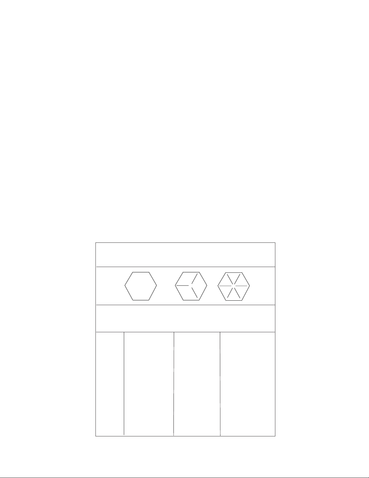
RECOMMENDED TORQUE VALUES CHART:
RECOMMENDED TORQUE IN FT.-LBS. (Nm)
COARSE AND FINE THREADS
2 (B)
Bolt Plain Three Six
Dia. Head Dashes Dashes
1/4" Not used 10 (14) 14 (19)
5/16" Not used 20 (27) 30 (41)
3/8" Not used 35 (47) 50 (68)
7/16" 35 (47) 55 (75) 80 (108)
1/2" 55 (75) 85 (115) 120 (163)
9/16" 75 (102) 130 (176) 175 (237)
5/8" 105 (142) 170 (230) 240 (325)
3/4" 185 (251) 300 (407) 425 (576)
7/8" 160 (217) 445 (603) 685 (929)
1" 250 (339) 670 (908) 1030 (1396)
1-1/8" 330 (447) 910 (1234) 1460 (1979)
1-1/4" 480 (651) 1250 (1695) 2060 (2793)
5 (D)
8 (F)
Interstater (McCormick CX-75, CX-85, CX-95 & CX-105 Asy. Man.) 07/05
© 2005 Alamo Group Inc.
0- 4
To help you assemble your new Brahma and mount it to your tractor, we provide you with
drawings, instructions, and general information. When needed, you can get information or
clarification from Your Dealer or Alamo Group Customer Service.
This publication provides general information not specifically for your case or tractor, but, in
connection with the drawings and Parts Section, this publication offers you some valuable
assistance - please read it thoroughly.
The mount kits are made for selected tractors with standard configurations. Only the noted
options and tire sizes listed in the model specifications will work with these mount kits. Other
options, front axles, or different tire sizes may prevent the mount kit from fitting your nonstandard
tractor. Alamo Group cannot take responsibility for these problems or any modifications made to
the unit.
Throughout these instructions, In the Parts Mnaual, Operators Manual and decals on unit you will
see the following symbles, pay close attenion to them. References are made to right or left
directions. Right and left are determined by sitting on the tractor seat and facing the direction of
travel.
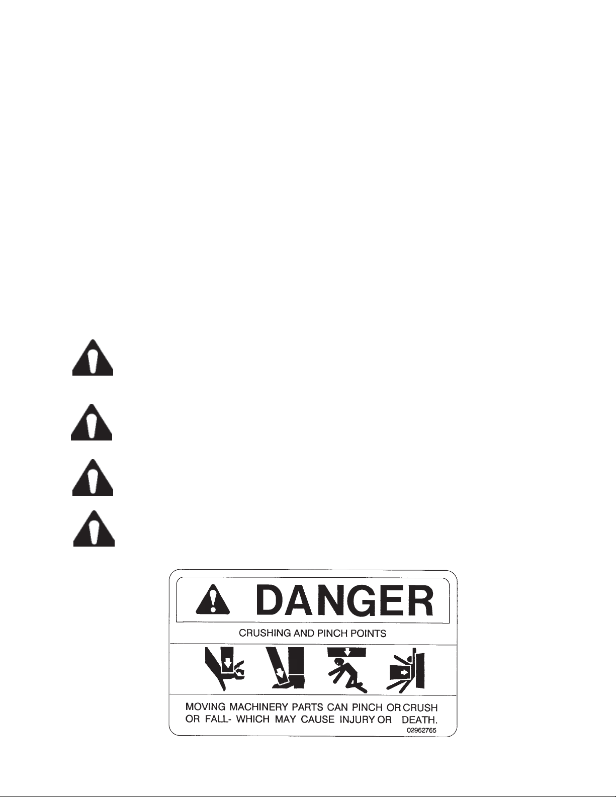
This is the Safety-Alert symbol. When you see this symbol on your machine
or in these instructions, be alert to the potential for personal injury. Follow
recommended precautions and safe operating practices.
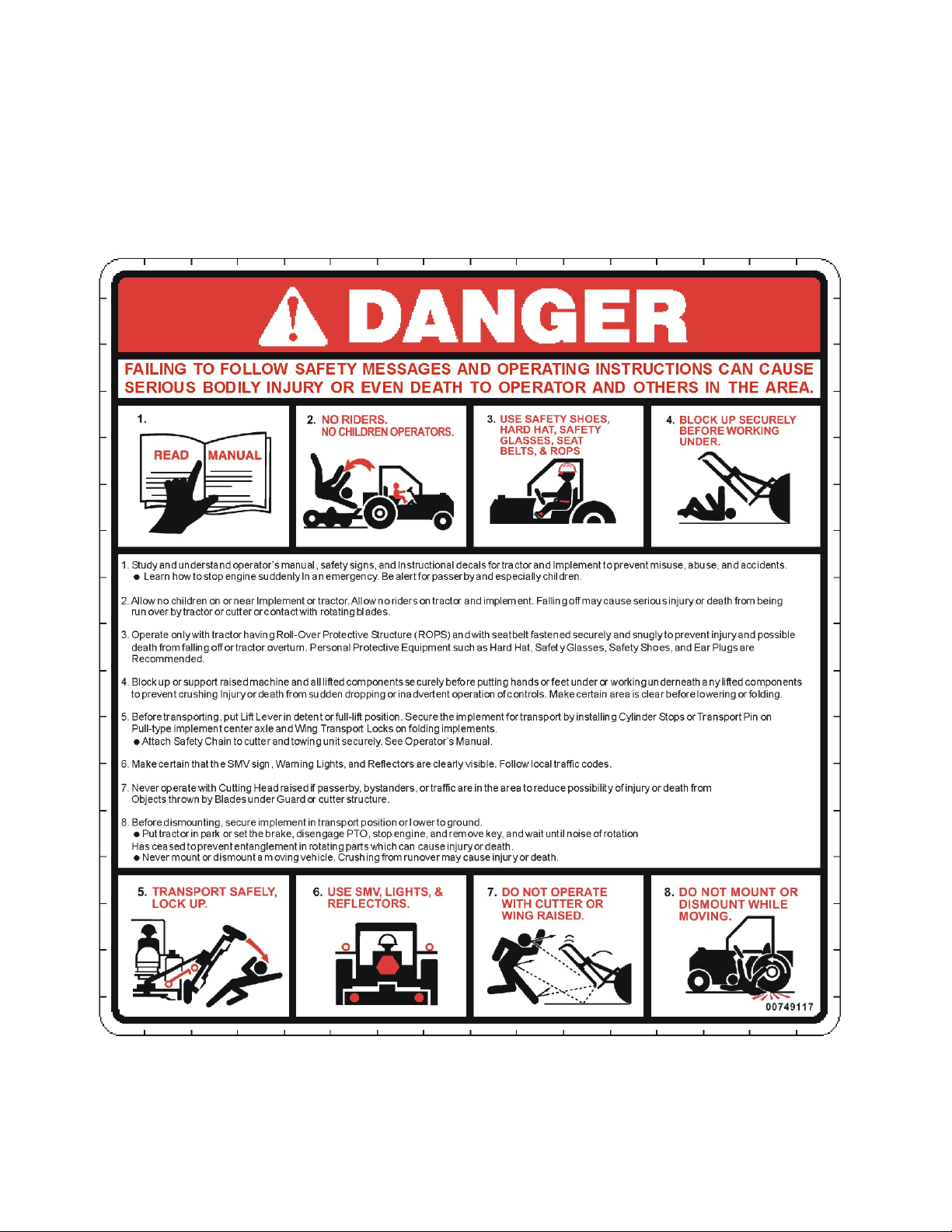
DANGER! A signal word - DANGER, WARNING, or CAUTION - is used with the Safety Alert
symbol. DANGER identifies the most serious hazards.
WARNING! Safety signs with signal word WARNING are typically used to point out
more serious hazards.
CAUTION! General precautions are listed on CAUTION safety sign. CAUTION also
calls attention to safety messages in these instructions.
Interstater (McCormick CX-75, CX-85, CX-95 & CX-105 Asy. Man.) 07/05
© 2005 Alamo Group Inc.
0- 5

NOTES
Interstater (McCormick CX-75, CX-85, CX-95 & CX-105 Asy. Man.) 07/05
© 2005 Alamo Group Inc.
0- 6

Section 1
INTERSTATER
McCormick
CX-75 / CX-85
CX-95 / CX-105
SAFETY
SECTION
Interstater (McCormick CX-75,CX85,CX95 & CX-105 Asy. Man.) 07/05
© 2005Alamo Group Inc.
Section 1 - 1
Tractor
Read these assembly instructions through completely and understand them
before proceeding with the assembly of the equipement.
A safe and careful operator is the best operator. Safety is of primary importance to the
manufacturer and should be to the owner/operator . Most accidents can be avoided by
being aware of your equipment, your surroundings, and observing certain precautions. The
first section of this manual includes a list of Safety Messages that, if followed, will help
protect the operator and bystanders from injury or death. Read and understand these
Safety Messages before assembling, operating or servicing this Implement. This equipment should only be operated by those persons who have read the Manual, who are re-
sponsible and trained, and who know how to do so safely and responsibly .
The Safety Alert Symbol combined with a Signal Word, as seen below, is used throughout
this manual and on decals which are attached to the equipment. The Safety Alert Symbol
means: “ATTENTION! BECOME ALERT! YOUR SAFETY IS INVOLVED!” The Symbol
and Signal Word are intended to warn the owner/operator of impending hazards and the
degree of possible injury faced when operating this equipment..
Practice all usual and customary safe working precautions and
above all---remember safety is up to YOU. Only YOU can prevent
serious injury or death from unsafe practices.
CAUTION! The lowest level of Safety Message; warns of possible injury. Decals
located on the Equipment with this Signal Word are Black and Yellow.
WARNING! Serious injury or possible death! Decals are Black and Orange.
DANGER! Imminent death/critical injury. Decals are Red and White. (SG-1)
Interstater (McCormick CX-75,CX85,CX95 & CX-105 Asy. Man.) 07/05
© 2005 Alamo Group Inc.
Section 1 - 2
PELIGRO!
Si no lee Ingles, pida ayuda a alguien que si lo lea para que le
traduzca las medidas de seguridad. (SG-3)
!LEA EL INSTRUCTIVO!
READ, UNDERSTAND, and FOLLOW the following Safety
Messages. Serious injury or death may occur unless care is
taken to follow the warnings and instructions stated in the Safety
Messages. Always use good common sense to avoid hazards.
(SG-2)
PELIGRO!
WARNING!
WARNING!
DANGER!
Si no lee Ingles, pida ayuda a alguien que
si lo lea para que le traduzca las medidas
de seguridad. (SG-3)
Perform service, repairs and lubrication according to the maintenance section. Ensure the unit
is properly lubricated as specified in the lubrication schedule and all bolts and nuts are properly
torqued. Failure to properly service, repair and maintain this Implement in good operating
condition could cause component failure and possible serious injury or even death. (SG-35)
Operate this Equipment only with a Tractor equipped with an
approved roll-over-protective system (ROPS). Always wear seat
belts. Serious injury or even death could result from falling off the
tractor--particularly during a turnover when the operator could be
pinned under the ROPS. (SG-7)
Never work under the Implement, the framework, or any lifted component unless the Implement is securely supported or blocked up to
prevent sudden or inadvertent falling which could cause serious injury
or even death. (SG-14)
INSTRUCTIVO!
!
LEA EL
WARNING!
Use caution and wear protective gloves when handling sharp objects such as blades, knives,
and other cutting edges. Be alert to worn component surfaces which have sharp edges. Sharp
surfaces can inflict severe laceration injuries if proper hand protection is not worn. (SG-37)
Interstater (McCormick CX-75,CX85,CX95 & CX-105 Asy. Man.) 07/05
© 2005Alamo Group Inc.
Section 1 - 3

WARNING!
Many of the parts are heavy and require lifting assistance. Do not try to
lift the heavy parts by yourself. Get help from another employee or from
an overhead crane.
WARNING!
WARNING!
WARNING!
The operator and all support personnel should wear hard hats,
safety shoes, safety glasses, and proper hearing protection at all
times for protection from injury including injury from items thrown by
the equipment. (SG-16)
Always wear safety shoes with steel toes when working on this equipment.
It is recommended that the safety shoes have metatarsal guards.
When welding use Welding hood with the appropriate OSHA required
protective lens, welding apron, and welding gloves.
DANGER!
DANGER!
Always disconnect the wire leads from the mower valve solenoid before
performing service on the Tractor or Mower. Use caution when working
on the Tractor or Mower. Tractor engine must be stopped before
working on Mower or Tractor. The Mower Blades could inadvertently be
turned on without warning and cause immediate dismemberment, injury
or death. (SBM-12)
Never run the tractor engine in a closed building or without adequate
ventilation. The exhaust fumes can be hazardous to your health.
(SG-23)
Interstater (McCormick CX-75,CX85,CX95 & CX-105 Asy. Man.) 07/05
© 2005 Alamo Group Inc.
Section 1 - 4

DANGER!
Before starting the mower make sure the area is clear and the floor has
been swept. The mower blade can throw objects several hundred feet.
Thrown objects could damge property or cause severe bodily injuries even
death.
WARNING!
DANGER!
DANGER!
Make certain that the “Slow Moving Vehicle” (SMV) sign is installed in
such a way as to be clearly visible and legible. When transporting the
Equipment use the Tractor flashing warning lights and follow all local traffic
regulations.
(SG-6)
Start tractor only when properly seated in the Tractor seat. Starting a
tractor in gear can result in injury or death. Read the Tractor operators
manual for proper starting instructions. (SG-13)
Do not operate this Equipment with hydraulic oil leaking. Oil is
expensive and its presence could present a hazard. Do not check for
leaks with your hand! Use a piece of heavy paper or cardboard. Highpressure oil streams from breaks in the line could penetrate the skin
and cause tissue damage including gangrene. If oil does penetrate the
skin, have the injury treated immediately by a physician knowledgeable and skilled in this procedure. (SG-15)
WARNING!
Always read carefully and comply fully with the manufacturers instructions when handling oil, solvents, cleansers, and any other chemical
agent. (SG-22)
DANGER!
All Safety Shields, Guards and Safety devices including
(but not limited to) - the Deflectors, Chain Guards, Steel
Guards, Gearbox Shields, PTO integral shields , and
Retractable Door Shields should be used and maintained in good working condition. All safety devices
should be inspected carefully at least daily for missing
or broken components. Missing, broken, or worn items
must be replaced at once to reduce the possibility of
injury or death from thrown objects, entanglement, or
blade contact. (SGM-3)
Interstater (McCormick CX-75,CX85,CX95 & CX-105 Asy. Man.) 07/05
© 2005Alamo Group Inc.
Section 1 - 5
DANGER!
NEVER use drugs or alcohol immediately before or while operating the
Tractor and Implement. Drugs and alcohol will affect an operator’s
alertness and coordination and therefore affect the operator’s ability to
operate the equipment safely. Before operating the Tractor or Implement, an operator on prescription or over-the-counter medication must
consult a medical professional regarding any side effects of the medication that would hinder their ability to operate the Equipment safely.
NEVER knowingly allow anyone to operate this equipment when their
alertness or coordination is impaired.
operator or others could result if the operator is under the influence of
drugs or alcohol. (SG-27)
Serious injury or death to the
DANGER!
WARNING!
WARNING!
WARNING!
Operate the Tractor and/or Implement controls only while properly seated
in the Tractor seat with the seat belt securely fastened around you.
Inadvertent movement of the Tractor or Implement may cause serious
injury or death. (SG-29)
Engine Exhaust, some of its constituents, and certain vehicle
components contain or emit chemicals known to the state of
California to cause cancer and birth defects or other
reproductive harm. (SG-30)
Battery posts, terminals and related accessories contain lead
and lead compounds, chemicals known to the state of California to cause cancer and birth defects or other reproductive
harm. W ash Hands after handling. (SG-31)
Use extreme caution when getting onto the Implement to perform repairs, maintenance and
when removing accumulated material. Only stand on solid flat surfaces to ensure good
footing. Use a ladder or raised stand to access high spots which cannot be reached from
gound level. Slipping and falling can cause serious injury or death. (SG-33)
WARNING!
WARNING!
Avoid contact with hot surfaces including hydraulic oil tanks, pumps, motors, valves and
hose connections. Relieve hydraulic pressure before performing maintenance or repairs.
Use gloves and eye protection when servicing hot components. Contact with a hot surface
or fluid can cause serious injury from burns or scalding. (SG-34)
Avoid contact with hot surfaces of the engine or muffler. Use gloves and eye protection
when servicing hot components. Contact with a hot surface or fluid can cause serious injury
from burns or scalding. (SG-38)
Interstater (McCormick CX-75,CX85,CX95 & CX-105 Asy. Man.) 07/05
© 2005 Alamo Group Inc.
Section 1 - 6

Section 2
INTERSTATER
McCormick
CX-75 / CX-85
CX-95 / CX-105
PRE-DELIVER Y INSPECTION
CHECKLIST
Interstater (McCormick CX-75,CX-85,CX-95 & CX-105 Asy. Man.) 07/05
Tractor
© 2005 Alamo Group Inc.
Section 2 - 1

INTERSTATER PRE-DELIVERY INSPECTION CHECKLIST
Pre-Operation Inspection: Check the following items before operating the unit to
assure that they are properly assembled. (See following page 1-4 for component location)
Saftey Equipment:
___ Operators Manual is with Unit.
___ The Safety Decals are installed as listed in the Assembly Manual.
___ Valve operation plate is installed.
___ Operators cage or Tractor Cab is in place
___ Deflectors are installed on the Mower Head
___ Tractor Rops or Cab with seatbels installed properly.
___ All Foot Guards and safety switch are installed and functional.
Frame:
___ Axle Plate Bolts are torqued.
___ Head Mounting Bolts tightened.
___ Frame attaching Bolts tightened.
___ Front Support Bolts are torqued.
___ Hydraulic Tank mounting Pins / Bolts in place correctly.
___ All Welds inspected toinsure proper welds and locations.
Hydraulic System:
___ Oil Level in Hydraulic Tank is within the sight gauge. (Item 5 page 1-4)
___ Hose connections are tight.
___ Hoses do not have any kinks or twist in them.
___ Front Pump Shaft adapter bolts are tight.
___ Front Pump Shaft Coupler / Drive Shaft is lubricated and has an anti-seize compound
on the Splines of Pump and Shafts.
___ The Pump Drive Shaft has correct alignment.
___ Suction Hose has no leaks or kinks.
Flail Mower Head:
___ Skid Shoe Bolts are torqued to 120 ft-lbs
___ Motor Bolts are torqued to 120 ft-lbs
___ Belt Alignment& tension adjustment is correct.
___ Cutter shaft bearings are properly lubricated
___ Roller bearings are properly lubricated
___ Blades swing freely.
___ All Pins and Clips for Rear Mower are installed
___ Clutch on Rear Mower has been checked for proper adjustment and conditions per
parts book reguirments.
___ All Belt guards are installed correctly.
Interstater (McCormick CX-75,CX-85,CX-95 & CX-105 Asy. Man.) 07/05
© 2005 Alamo Group Inc.
Section 2 - 2

INTERSTATER PRE-DELIVERY INSPECTION CHECKLIST
Pre-Operation Inspection: Check the following items before operating the unit to assure
that they are properly assembled. (See following page 1-4 for component location)
Tractor Mower Operation Inspection:
Using all Safety precautions, operate the Tractor and Mower unit for 30 minutes and
while the unit is running check the following items: Note! Only make adjustments after
the mower has been turned off and all motion has stopped and all hydraulic pressure
has been relieved.
___ Check for Hydraulic oil leaks at the hose connections
___ Operate the boom and mower head throughout its full range of motion and check
for hose's rubbing, pinching, or kinking.
___ Make sure the Return Filter Gauge is reading in the Green after Oil is warm.
___ Check the function of the Mower Head On-Off Valve and switch for proper function
___ Make sure that the tractor will not start with the mower on-off switch in the on
position.
___ Check the Blade Rotation for the Rotary Mower Head to make sure it is turning
Clockwise looking from the top of the mower deck.
___ Make sure the control valve boom movements agree with the valve operation decal.
___ Make Sure Boom Movement operates as expected and is smooth and under control
(no air in the control system)
___ Look for any unusual or excessive noise or vibrations.
___ Make sure the left rear wheel of the tractor stays on the ground when the boom is
fully extended horizontally with 200 lbs. placed on the outside of the mower head.
Post-Operation Inspection:
___ Check that the oil in the hydraulic tank has not turned milky in color or has foam on top.
___ Check that there are no loose fasteners or hardware.
Interstater (McCormick CX-75,CX-85,CX-95 & CX-105 Asy. Man.) 07/05
© 2005 Alamo Group Inc.
Section 2 - 3
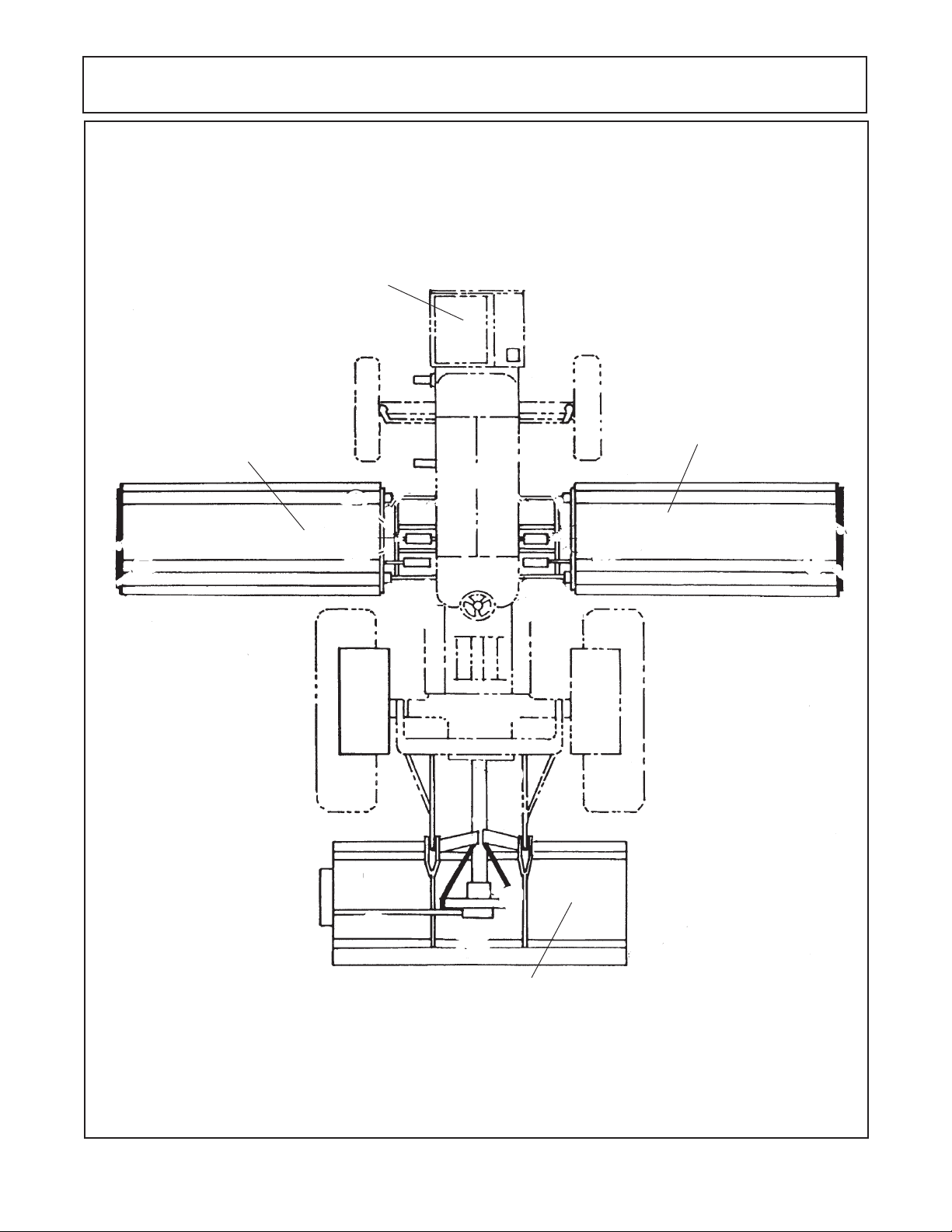
Tractor - Mower Component Location
For Check List
Pumps, Hyd.
Tank & Cover
Left Wing
Flail
LH SIDE OF
TRACTOR
Right Wing
Flail
RH SIDE OF
TRACTOR
Rear Center
Flail
Interstater (McCormick CX-75,CX-85,CX-95 & CX-105 Asy. Man.) 07/05
© 2005 Alamo Group Inc.
Section 2 - 4

Section 3
INTERSTATER
McCormick
CX-75 / CX-85
CX-95 / CX-105
Mainframe Installation
Interstater (McCormick CX-75, CX-85, CX-95 & CX-105 Asy. Man.) 07/05
Tractor
© 2005 Alamo Group Inc.
Section 3 - 1
Install Main Frame / RH Wing Only
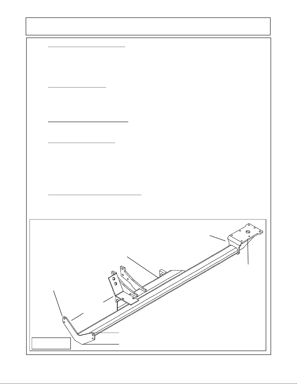
1. Identify and locate the frame rail It will be easier to install the sub-frame before the pump,
driveshaft and tank, it will be easier to align the front mounting bolts of the sub-frame. T wo Wheel Drive
Tractors use different sub-frame than the four wheel drive tractor, The sub-frame must match the
tractor as they will not interchange. To determine if you have the correct sub-frame check the measurement shown (See Figure 1 & 2)
2. Remove RH Side S teps. The steps on the RH side of the tractor will be removed and not used
so as not to interfere with the clearance of the mower head. The factory toolbox (if equipped) will need
to be removed also for clearance. It will be dealer and/or customers choice on where and wether the
toolbox can be remounted somewhere else for use, it is up to you..
3. Rear Draw Bar Bracket Removed The rear draw bar bracket will need to be removed as this
is where the rear section of the sub-frame will connect to the rear axle of the tractor.
4. Install Frame Rail to Tractor. The frame rail (Figure 1 or 2) will be slid under the tractor on the
RH side (See Figure 3). Make certain the plastic plugs have been removed from tractor frame, at the
front bolster and the center ones at the rear axle.. Do NOT tighten the frame mounting bolts until all the
bolts have been installed as frame will need to be moved slightly for alignment as the bolts are installed.
The frame can be installed by balancing the frame on a floor jack, if using this method it is recommended two people perform this to prevent the frame from falling. Raise the frame up to the tractor
frame (See Figure 3),
5. Raise the frame rail up under the tractor . Raise sub-frame under tractor until the rear mounting
plate is under the rear axle and aligned with the bolt holes that did mount the draw bar bracket to the
rear axle. Using the jack raise the frame up until it is against the rear axle housing. Install the new bolts,
nuts, lockwashers, flatwashers and the axle strap (See Figure 1, 2, 3 & 4).
P/N 02982467
6-3/16" Tall
Sub-Frame Asy. RH Wing Only
(2 WDTractors With Cab)
Rear Mounting
Front Support
Plates of Sub-Frame
35-9/16"
Plate of Sub-Frame
Figure 1
Interstater (McCormick CX-75, CX-85, CX-95 & CX-105 Asy. Man.) 07/05
© 2005 Alamo Group Inc.
9-1/2" Tall
Section 3 - 2
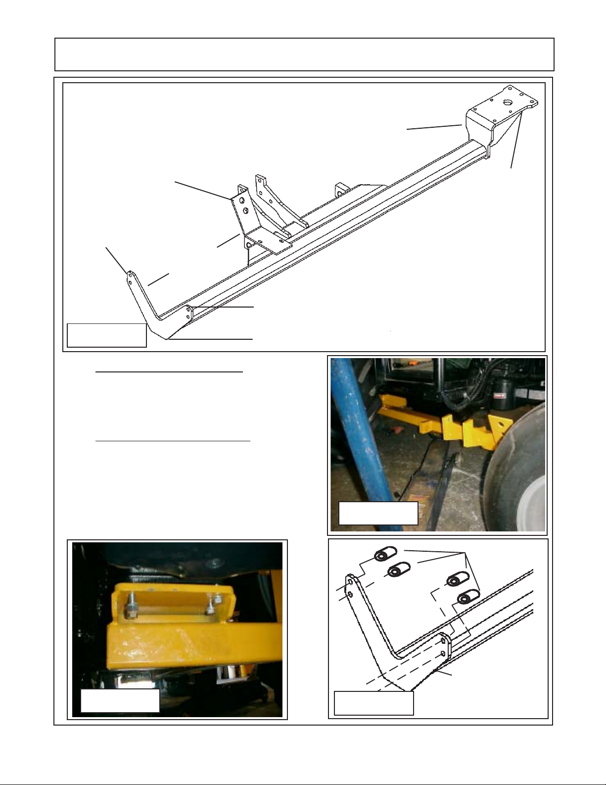
Install Main Frame / RH Wing Only
P/N 02982018
Sub-Frame Asy. RH Wing Only
(4 WD Tractors With Cab)
Front Support
Plates of Sub-Frame
38-9/16"
12-1/2" Tall
Figure 2
9-3/16" Tall
Rear Mounting
Plate of Sub-Frame
6. Start The Rear frame Rail Bolts. The bolts in the
rear of the sub-frame should be started but not tightened, this will allow the frame to be moved around to
align the front bolts (See Figure 4.
7. Frame Rail Front Mounting Bolts. Install the front
frame rail mounting bolts (See Figure 5). The front subframe bolts will bolt to the front bolster behind the tank.
There are 4 2" log spacers that are installed between
the frame and bolster. Do not tighten the bolts until all
the bolts are installed in frame rail. Leave floor jack and/
or stands under frame rail until completely mounted (See
Figure 5).
Figure 3
Spacers
Figure 4
Interstater (McCormick CX-75, CX-85, CX-95 & CX-105 Asy. Man.) 07/05
© 2005 Alamo Group Inc.
Section 3 - 3
Figure 5
Front Support
Plates of Sub-Frame
 Loading...