

Page 1
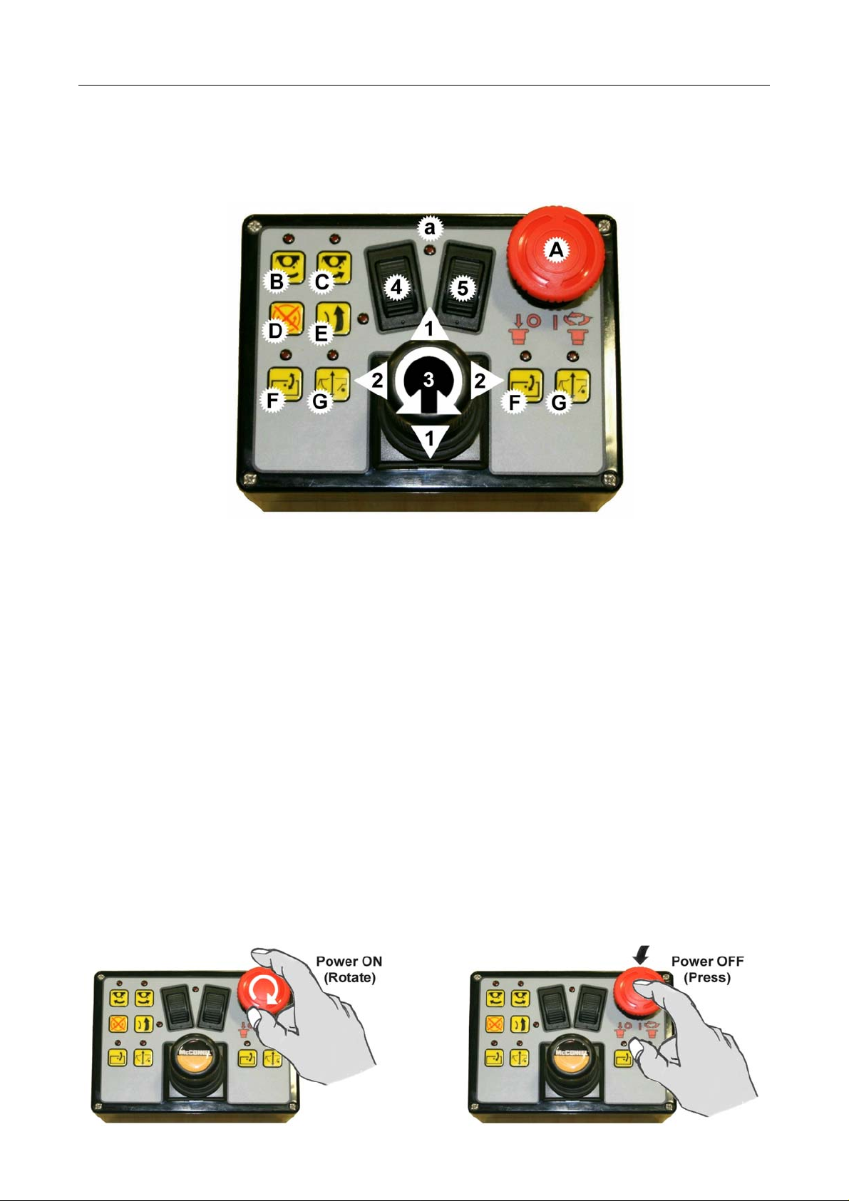
XTC (Mk2) PROPORTIONAL SWITCHBOX CONTROLS (5 Service Models)
(
Machines with XTC Mk2 Proportional Controls (5 service models) will be supplied with the
control unit shown below. The units for both electric and cable controlled rotor machines
are identical except that for cable versions the rotor control switches B, C & D (shown
below) will not provide a function as rotor operation will be controlled by a separate cable
lever unit (refer to specific cable rotor control page for operation details of that unit).
LOCATION & FUNCTION OF CONTROLS
1. Arm Lift Control
2. Arm Reach Control
3. Head Angle Control
4. Arm Slew Control (Default Mode)
5. Tele*/Midcut*/VFR* Control (Default Mode)
* Applies to the specific model only
A. Power On/Off (LED ‘a’ indicates status)
B. Rotor Start (Uphill Cutting Direction)
C. Rotor Start (Downhill Cutting Direction)
D. Rotor Stop
E. Auto Reset
F. Head Angle Float On/Off
G. Lift Float On/Off
Option)
Note: 2 sets of control buttons are installed on each side of the unit for operation of Angle Float &
Lift Float, both sets of buttons and their LED’s are linked and therefore perform exactly the same
function; they are installed to allow for operator preference.
LED Lights
An LED light adjacent to each control button reports the status of that particular function –
when the function is selected the LED light will illuminate to confirm the function is active;
the light will switch off on de-selection of that function.
Powering the Controls
Activation of power to the control unit is by operation of the red button switch ‘A’ as shown
below:
Rotate clockwise for Power ON (LED light on)
Press for Power OFF / Emergency Stop (LED light off)
Page 2
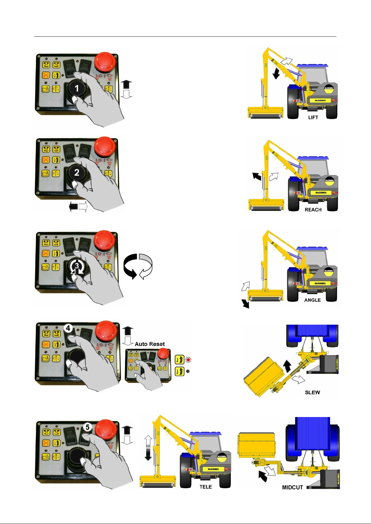
ARM OPERATION
Tele or Midcut/VFR Models only
Page 3
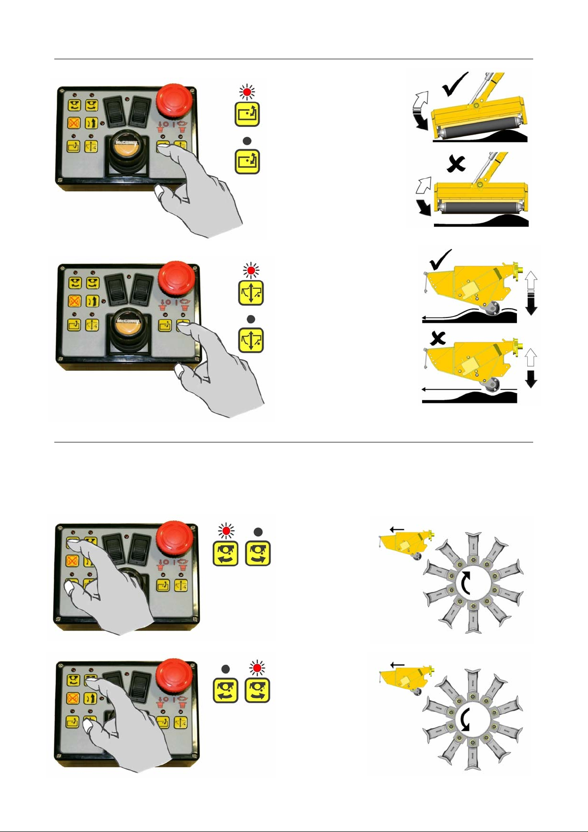
HEAD FLOAT OPERATION
Angle Float (Standard Feature)
Lift Float (Optional Feature)
ROTOR OPERATION – Electric Rotor Control Models only
NOTE: The following section relates to machines with electric rotor control only – for cable rotor
control models refer to the specific cable rotor control section.
Rotor Start (Selection of Rotor Cutting Direction)
Select rotor start for required direction (LED will light to indicate the active direction).
Uphill Cutting
Downhill Cutting
Page 4
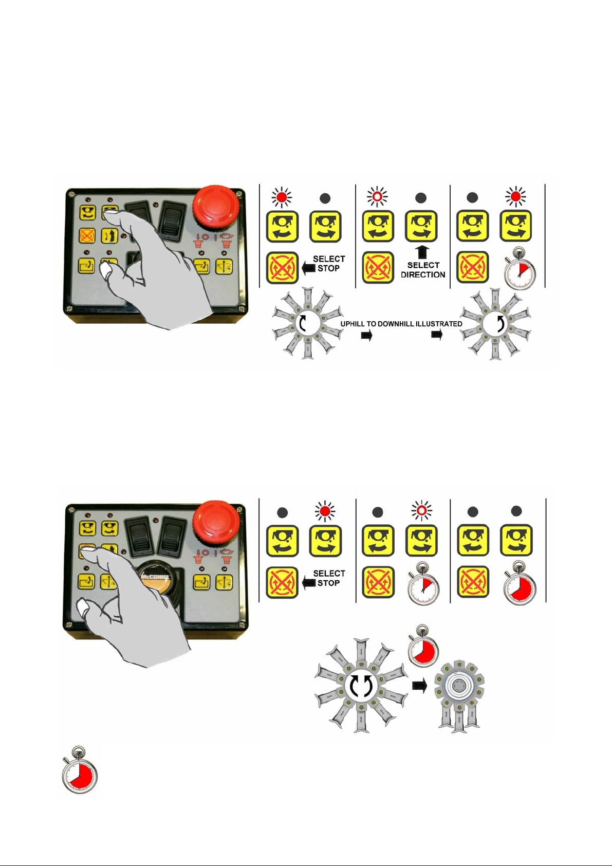
Switching Rotor Direction
With the rotor running, changing the rotor cutting direction can only be achieved after first
operating ‘rotor stop’, when stop has been selected the specific direction button can then
be operated to command the rotor to switch to the desired direction. NOTE: This function
has a built in time delay of approximately 8 seconds - this is a machine protection feature
that allows the rotor sufficient time to de-accelerate before restarting in the opposite
direction. The LED light of the active cutting direction will flash on and off during the
slowing down period, when the direction has changed the LED for the new direction will be
illuminated.
Switching the Rotor Off
Stopping the rotor is performed by operation of the rotor stop button as illustrated below.
When rotor off has been selected the LED light above the button of the active cutting
direction will flash on and off for approximately 8 seconds to signify that the rotor has been
switched off, after this 8 second period the light will go off completely. NOTE: The rotor will
continue to rotate under its own power until it finally comes to a standstill.
CAUTION: When the rotor is switched off it will continue to ‘freewheel’ under its own
momentum for up to 40 seconds before finally coming to a standstill – do not leave the
tractor cab or attempt to approach the flailhead until the rotor has stopped turning
completely.
 Loading...