

Page 1
Publication 679
August 2011
Part No. 22674.79
Revision: 30.06.17
McCONNEL
ROBOCUT
REMOTE CONTROLLED MOWER
Operator & Parts Manual
Machines from 07-13 / Serial No. 011400323 ►
Page 2
IMPORTANT
VERIFICATION OF WARRANTY REGISTRATION
DEALER WARRANTY INFORMATION & REGISTRATION VERIFICATION
It is imperative that the selling dealer registers this machine with McConnel Limited before
delivery to the end user – failure to do so may affect the validity of the machine warranty.
To register machines go to the McConnel Limited web site at www.mcconnel.com, log
onto ‘Dealer Inside’ and select the ‘Machine Registration button’ which can be found in
the Service Section of the site. Confirm to the customer that the machine has been
registered in the section below.
Should you experience any problems registering a machine in this manner please contact
the McConnel Service Department on 01584 875848.
Registration Verification
Dealer Name:
……………………..…………………………………………………………….
Dealer Address:
…….………………………………………………………………………….
Customer Name:
……………………..…………………………………………………………
Date of Warranty Registration:
……/……/...…… Dealer Signature: ………………..……
NOTE TO CUSTOMER / OWNER
Please ensure that the above section above has been completed and signed by the selling
dealer to verify that your machine has been registered with McConnel Limited.
IMPORTANT: During the initial ‘bedding in’ period of a new machine it is the customer’s responsibility
to regularly inspect all nuts, bolts and hose connections for tightness and re-tighten if required. New
hydraulic connections occasionally weep small amounts of oil as the seals and joints settle in – where
this occurs it can be cured by re-tightening the connection – refer to torque settings chart below. The
tasks stated above should be performed on an hourly basis during the first day of work and at least
daily thereafter as part of the machines general maintenance procedure.
CAUTION: DO NOT OVER TORQUE HYDRAULIC FITTING S AND HOSES
TORQUE SETTINGS FOR HYDRAULIC FITTINGS
HYDRAULIC HOSE ENDS PORT ADAPTORS WITH BONDED SEALS
BSP
Setting
Metric
BSP
Setting
Metric
1/4” 18 Nm 19 mm 1/4” 34 Nm
19 mm
3/8” 31 Nm 22 mm 3/8” 47 Nm
22 mm
1/2” 49 Nm 27 mm 1/2” 102 Nm
27 mm
5/8” 60 Nm 30 mm 5/8” 122 Nm
30 mm
3/4” 80 Nm 32 mm 3/4” 149 Nm
32 mm
1” 125 Nm 41 mm 1” 203 Nm
41 mm
1.1/4”
190 Nm
50 mm
1.1/4”
305 Nm
50 mm
1.1/2” 250 Nm 55 mm 1.1/2” 305 Nm
55 mm
2” 420 Nm 70 mm 2” 400 Nm
70 mm
Page 3

WARRANTY POLICY
WARRANTY REGISTRATION
All machines must be registered, by the selling dealer with McConnel Ltd, before delivery to the
end user. On receipt of the goods it is the buyer’s responsibility to check that the Verification of
Warranty Registration in the Operator’s Manual has been completed by the selling dealer.
1. LIMITED WARRANTIES
1.01. All machines supplied by McConnel Ltd are warranted to be free from defects in material and
workmanship from the date of sale to the original purchaser for a period of 12 months, unless
a different period is specified.
1.02. All spare parts supplied by McConnel Ltd and purchased by the end user are warranted to be
free from defects in material and workmanship from the date of sale to the original purchaser
for a period of 6 months. All parts warranty claims must be supported by a copy of the failed
part invoice to the end user. We cannot consider claims for which sales invoices are not
available.
1.03. The warranty offered by McConnel Ltd is limited to the making good by repair or replacement
for the purchaser any part or parts found, upon examination at its factory, to be defective
under normal use and service due to defects in material or workmanship. Returned parts
must be complete and unexamined. Pack the component(s) carefully so that any transit
damage is avoided. All ports on hydraulic items should be drained of oil and securely plugged
to prevent seepage and foreign body ingress. Certain other components, electrical items for
example, may require particular care when packing to avoid damage in transit.
1.04. This warranty does not extend to any product from which McConnel Ltd’s serial number plate
has been removed or altered.
1.05. This warranty does not apply to any part of the goods, which has been subjected to improper
or abnormal use, negligence, alteration, modification, fitment of non-genuine parts, accident
damage, or damage resulting from contact with overhead power lines, damage caused by
foreign objects (e.g. stones, iron, material other than vegetation), failure due to lack of
maintenance, use of incorrect oil or lubricants, contamination of the oil, or which has served
its normal life. This warranty does not apply to any expendable items such as blades, belts,
clutch linings, filter elements, flails, flap kits, skids, soil engaging parts, shields, guards, wear
pads, pneumatic tyres or tracks.
1.06. Temporary repairs and consequential loss - i.e. oil, downtime and associated parts are
specifically excluded from the warranty.
1.07. Warranty on hoses is limited to 12 months and does not include hoses which have suffered
external damage. Only complete hoses may be returned under warranty, any which have
been cut or repaired will be rejected.
1.08. Machines must be repaired immediately a problem arises. Continued use of the machine
after a problem has occurred can result in further component failures, for which McConnel Ltd
cannot be held liable, and may have safety implications.
1.09. If in exceptional circumstances a non McConnel Ltd part is used to effect a repair, warranty
reimbursement will be at no more than McConnel Ltd’s standard dealer cost for the genuine
part.
1.10. Except as provided herein, no employee, agent, dealer or other person is authorised to give
any warranties of any nature on behalf of McConnel Ltd.
1.11. For machine warranty periods in excess of 12 months the following additional exclusions
shall apply:
1.11.1. Hoses, exposed pipes and hydraulic tank breathers.
1.11.2. Filters.
1.11.3. Rubber mountings.
1.11.4. External electric wiring.
1.11.5. Bearings and seals.
Page 4

1.12. All service work, particularly filter changes, must be carried out in accordance with the
manufacturer’s service schedule. Failure to comply will invalidate the warranty. In the event of
a claim, proof of the service work being carried out may be required.
1.13. Repeat or additional repairs resulting from incorrect diagnosis or poor quality previous repair
work are excluded from warranty.
NB Warranty cover will be invalid if any non-genuine parts have been fitted or used. Use of non-
genuine parts may seriously affect the machine’s performance and safety. McConnel Ltd cannot be
held responsible for any failures or safety implications that arise due to the use of non-genuine parts.
2. REMEDIES AND PROCEDURES
2.01. The warranty is not effective unless the Selling Dealer registers the machine, via the
McConnel Ltd web site and confirms the registration to the purchaser by completing the
confirmation form in the operator’s manual.
2.02. Any fault must be reported to an authorised McConnel Ltd dealer as soon as it occurs.
Continued use of a machine, after a fault has occurred, can result in further component
failure for which McConnel Ltd cannot be held liable.
2.03. Repairs should be undertaken within two days of the failure. Claims submitted for repairs
undertaken more than 2 weeks after a failure has occurred, or 2 days after the parts were
supplied will be rejected, unless the delay has been authorised by McConnel Ltd. Please
note that failure by the customer to release the machine for repair will not be accepted as a
reason for delay in repair or submitting warranty claims.
2.04. All claims must be submitted, by an authorised McConnel Ltd Service Dealer, within 30 days
of the date of repair.
2.05. Following examination of the claim and parts, McConnel Ltd will pay, at their discretion, for
any valid claim the invoiced cost of any parts supplied by McConnel Ltd and appropriate
labour and mileage allowances if applicable.
2.06. The submission of a claim is not a guarantee of payment.
2.07. Any decision reached by McConnel Ltd is final.
3. LIMITATION OF LIABILITY
3.01. McConnel Ltd disclaims any express (except as set forth herein) and implied warranties with
respect to the goods including, but not limited to, merchantability and fitness for a particular
purpose.
3.02. McConnel Ltd makes no warranty as to the design, capability, capacity or suitability for use of
the goods.
3.03. Except as provided herein, McConnel Ltd shall have no liability or responsibility to the
purchaser or any other person or entity with respect to any liability, loss, or damage caused
or alleged to be caused directly or indirectly by the goods including, but not limited to, any
indirect, special, consequential, or incidental damages resulting from the use or operation of
the goods or any breach of this warranty. Notwithstanding the above limitations and
warranties, the manufacturer’s liability hereunder for damages incurred by the purchaser or
others shall not exceed the price of the goods.
3.04. No action arising out of any claimed breach of this warranty or transactions under this
warranty may be brought more than one (1) year after the cause of the action has occurred.
4. MISCELLANEOUS
4.01. McConnel Ltd may waive compliance with any of the terms of this limited warranty, but no
waiver of any terms shall be deemed to be a waiver of any other term.
4.02. If any provision of this limited warranty shall violate any applicable law and is held to be
unenforceable, then the invalidity of such provision shall not invalidate any other provisions
herein.
4.03. Applicable law may provide rights and benefits to the purchaser in addition to those provided
herein.
Page 5

DECLARATION OF CONFORMITY
Conforming to EU Machinery Directive 2006/42/EC
We,
McCONNEL LIMITED, Temeside Works, Ludlow, Shropshire SY8 1JL, UK
Hereby declare that:
The Product; Radio Controlled Tracked Mower
Product Code; RMOW
Serial No. & Date ………………………………… Type …………………………
Manufactured in; Italy
Complies with the required provisions of the Machinery Directive 2006/42/EC
The machinery directive is supported by the following harmonized standards;
BS EN ISO 12100 (2010) Safety of machinery – General principles for design – Risk
assessment and risk reduction.
BS EN 349 (1993) + A1 (2008) Safety of machinery - Minimum distances to avoid the
entrapment with human body parts.
BS EN 953 (1997) + A1 (2009) Safety of machinery - Guards general requirements for
the design and construction of fixed and movable guards.
BS EN 4413 (2010) Hydraulic fluid power. Safety requirements for systems and their
components.
McCONNEL LIMITED operates an ISO 9001:2008 quality management system,
certificate number: FM25970.
This system is continually assessed by the;
British Standards Institution (BSI), Beech House, Milton Keynes, MK14 6ES, UK
BSI is accredited by UK Accreditation Service, accreditation number: UKAS 003.
The EC declaration only applies if the machine stated above is used in
accordance with the operating instructions.
Signed …………………................ Responsible Person
CHRISTIAN DAVIES on behalf of McCONNEL LIMITED
Status: General Manager Date: September 2015
Page 6

For Safety and Performance…
ALWAYS READ THIS BOOK FIRST
McCONNEL LIMITED
Temeside Works
Ludlow
Shropshire
England
Telephone: 01584 873131
www.mcconnel.com
Page 7

Page 8

LIST OF CONTENTS
Page No.
Operator Section
General Information 1
Features & Specifications 2
Safety Information 3
Safety Decals & Warnings 6
Safety Devices & Emergency Stop 7
Machine Delivery 8
Machine Overview 9
Display LCD 11
Radio Control Unit 15
Starting the Engine 16
Driving & Manoeuvring 17
Emergency Manual Control Unit 22
Pre-Operation Checks 24
Operation 25
Operating Position & Distance 27
Maintenance 28
Undercarriage Specifications 40
Electrical System Fuses & Relays 41
Troubleshooting 42
Parts Section
Chassis Assembly 2
Track Roller Assemblies 4
Track Tensioner Assemblies 6
Rubber Tracks 8
Equipment Mounting Assembly 10
Engine Cover Assembly 12
Radiator Cover Assembly 14
Machine Cover Assembly 16
Roll bar Assembly 18
Diesel Engine 20
Diesel Engine Components 24
Pumps Assembly (Early Machines) 26
Pumps Assembly (Current Machines) 28
Actuator Assembly 30
Reversible Fan Assemblies 32
Diesel Fuel Circuit 38
Oil Tank Assembly 40
Electrical Components 42
Electrical Wiring 46
Control Transmitting / Receiving Units 48
Intake & Drain Pumps 50
Tracks Hydraulic Circuit 52
Hydraulic Rams Circuit 54
Hydraulic Equipment Circuit 56
Flailhead Assembly 58
Rotors & Flails 66
Flailhead Hydraulic Assembly 70
Decal Kit 74
Service Parts 75
Page 9

Page 10
1
GENERAL INFORMATION
Always read this manual before attempting to operate the machine – whenever any doubt exists
contact your dealer or the McConnel Service Department for advice and assistance.
Use only McConnel Genuine Service Parts on McConnel Equipment and Machines
DEFINITIONS – The following definitions apply throughout this manual:
WARNING
An operating procedure, technique etc., which –
can result in personal injury or loss of life if not observed carefully.
CAUTION
An operating procedure, technique etc., which –
can result in damage to either machine or equipment if not observed carefully.
NOTE
An operating procedure, technique etc., which is –
considered essential to emphasis.
LEFT AND RIGHT HAND
These terms are applicable to the machine when it is viewed from the rear facing forwards.
Note: The illustrations in this manual are for instructional purposes only and may on occasion not show
some components in their entirety. In some instances an illustration may appear slightly different to that of
your particular model but the general procedure will be the same. E&OA.
MACHINE & DEALER INFORMATION
Record the Serial Number of your machine on this page and always quote this number when
ordering parts. Whenever information concerning the machine is requested remember also
to state the make and model of tractor to which the machine is fitted.
Machine Serial Number: Installation Date:
Machine Model details:
Dealer Name:
Dealer Address:
Dealer Telephone No:
Dealer Email Address:
Page 11
2
FEATURES & SPECIFICATIONS
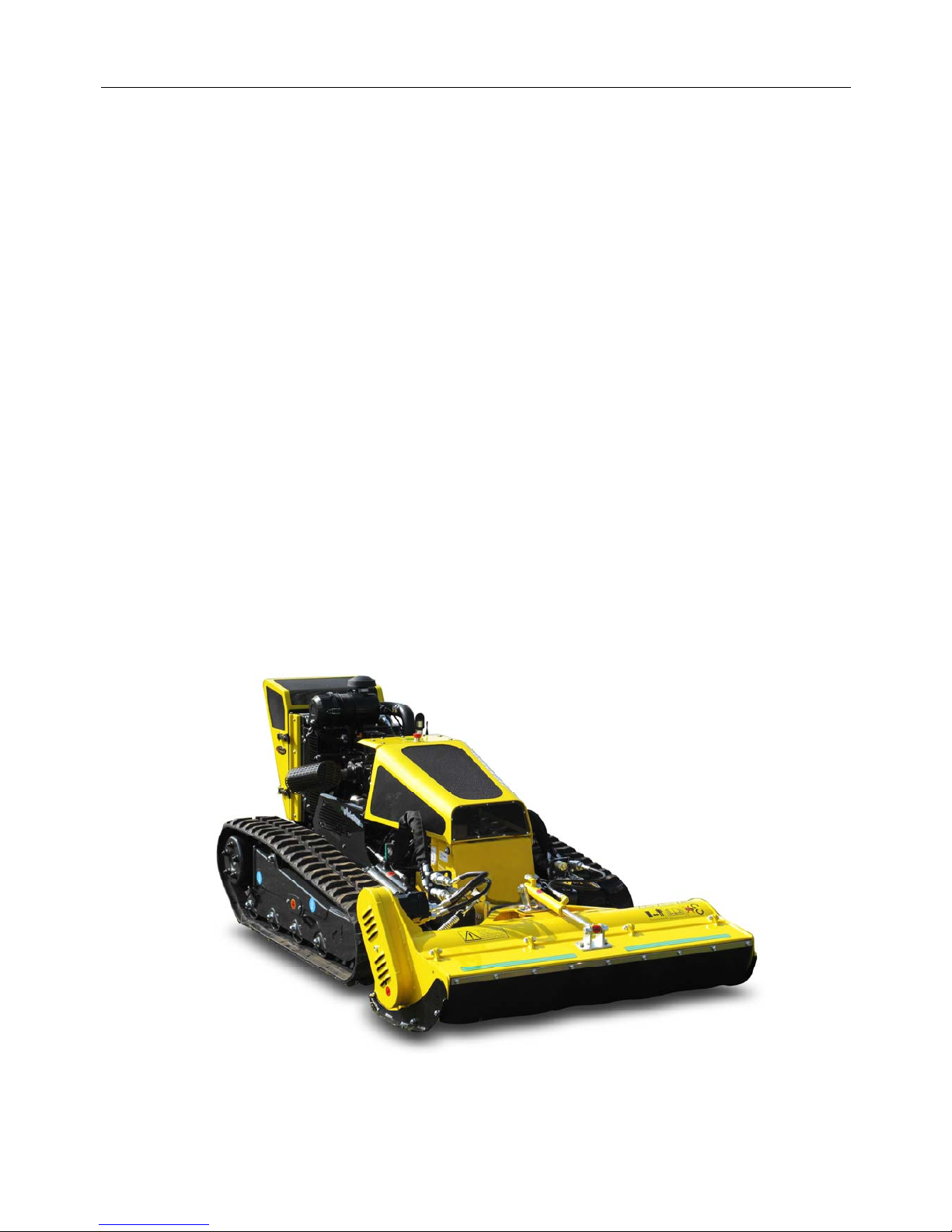
RoboCut
○ 40HP (29kW) 3 Cylinder ISUZU Diesel Engine
○ Tracked Carriage Hydraulically Driven via Piston Pumps
○ Self-Tightening Tracks
○ Remote Controlled Operation (up to 150m range)
○ Rubber Tracks with Removable Riveted Stirrups
○ Rubber Stopper Spike Protection for Transport
○ Potentiometer Speed Control from 0 to 100%
○ Independent Cooling System for Hydraulic Circuits
○ Self-Cleaning Reversible Fan
○ Electronically Controlled, Hydraulically Powered Flail Head
○ Proportional Joystick Speed Control – Forwards & Backwards 0 to 7km/h
○ 21 Litre Fuel Tank Capacity
○ 1280mm Carriage Width
○ 1.3m Flail Head capable of cutting materials up to 30mm diameter
○ Machine Weight 1000kg
Page 12
3
SAFETY INFORMATION
This machine has the potential to be extremely dangerous - in the wrong hands it can kill or
maim; It is therefore imperative that both owner and operator of the machine reads and
understands the following section to ensure they are fully aware of the dangers that do, or may
exist, and their responsibilities surrounding the use and operation of the machine.
The operator of this machine is responsible not only for their own safety but equally for the
safety of others who may come into the close proximity of the machine, as the owner you are
responsible for both.
When the machine is not in use it should be parked on a firm level site with the cutting head
resting on the ground and the starting key removed.
In the event of any fault being detected with the machine’s operation it must be stopped
immediately and not used again until the fault has been corrected by a qualified technician.
Before starting the machine the operator must read and understand all aspects of use and
maintenance of the machine as stated in this manual.
The machine must only be used by a responsible adult who is familiar with all aspects
relating to safe operation.
The machine must not be operated by children or non-authorised persons.
Operators must know the meaning of all operation and safety decals on both the machine
and the remote control unit.
Operators must know the procedure for switching the machine off normally and the correct
procedure for using the Emergency Stop.
Do not attempt to use the machine if the Emergency Stop switch is damaged or
malfunctioning.
Never use the machine with safety guarding removed or defective.
Page 13

4
Operators should practice operation on flat open ground to familiarise themselves with
driving and manoeuvring the machine before attempting to use it on sloping ground.
Operators should practice manoeuvring the machine around obstacles without the flail head
running before using the machine for work purposes.
Never operate the machine when your vision is blocked by obstacles such as vehicles,
buildings, hedges etc.; move to a position where you have an un-interrupted view of the
machine.
Never operate the machine standing directly in the line of travel.
Do not use the machine on sand piles, gravel, or similar materials.
Only operate the machine in good light conditions.
Never run the machine in an enclosed area or building.
Keep the machine clean to avoid build ups of dry materials that could ignite on hot
components.
Never stand directly below a machine that is operating or parked on a slope.
Always operate the joystick control slowly; rapid or jerky movements can cause the machine
to rear up causing loss of control.
When operating the machine with the flail head running the operator must remain at least 5
metres away from the machine; always switch the flail head off before approaching it.
When using the machine the operator should place themselves in a position that provides
optimum visibility over the work area.
Never leave a running machine unattended; always switch the engine off and remove the
ignition key.
Always stop and switch the machine off if persons or animals enter the work area, do not
restart the machine until they are at a safe distance.
Never use the machine to perform tasks it was not designed for.
Never ride, or allow others to ride on the machine.
Always inspect the work area prior to operation and remove stones, glass, metal, wire or any
other foreign objects that are hazardous. Immovable hazards should be ‘marked’ so they
can be avoided.
Take extra care when operating the machine on slopes or uneven ground, there is increased
risk of objects being thrown from the flail head when working in these conditions.
The machine can be used on slopes up to a maximum of 55° (track option dependant)
providing the surface is dry and firm.
Page 14

5
Should a machine overturn, a suitable crane or winch should be used to recover it, keep all
persons at a safe distance before and during recovery.
Do not operate the machine in foggy or frosty conditions as there is increased risk of
accidents.
Take extra care when working in close proximity to electrical cables; in some circumstances,
operating the machine under overhead power lines can result in loss of radio signal causing
the engine to deactivate.
Do not operate the machine close to vehicles or properties where there is risk of damage by
objects accidentally thrown from the flail head.
It is the user’s responsibility to protect persons in or near the work zone.
When servicing or maintaining the machine no one should be allowed beneath it when it is
raised unless it is securely supported on suitable ramps or stands.
Never attempt to service or maintain the machine whilst it is running; always switch off the
engine and remove the starting key.
When transporting the machine on another vehicle or trailer the engine must be switched off
and the machine chocked and secured using suitable ropes or chains.
Check the condition of the flails and fixings on a regular basis; never use the machine with
damaged/missing flails or loose fixings.
Always clean the machine after use; care must be taken if the machine is hot. Never use
solvent based chemicals for cleaning.
When operating in excessively dusty conditions work may need to be interrupted on a
regular basis to remove any build ups of dust on components that could cause overheating.
Ensure engine is switched off and Emergency Stop switch is in the ‘off’ position before
refuelling.
Wherever possible refuel the machine before work when the engine is cold. If refuelling
during work, switch off the engine and allow it to cool before adding fuel.
Test the Emergency Stop switch before each period of work to ensure it functions correctly.
Never leave the machine, ignition key and control unit unattended where it could be started
and used by un-authorised persons.
Any inspection, service or maintenance of the flail head must only be performed with
machine switched off and the starting key removed.
Always wear safety gloves and glasses when performing service or maintenance on the flail
head.
Flail head must always be switched off when manoeuvring outside of the work zone.
Page 15
6
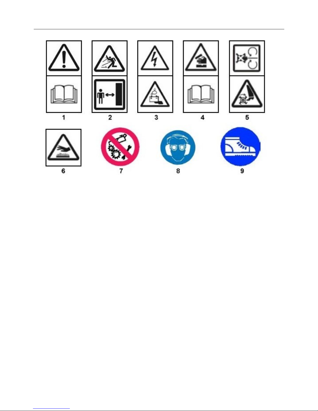
SAFETY & WARNING DECALS
1. WARNING: Read the manual first.
2. DANGER: Risk of thrown objects, keep your distance.
3. DANGER: Electrical voltage and harmful substances.
4. DANGER: Acid, read the user and maintenance manual.
5. DANGER: Rotating components, keep clear.
6. DANGER: Hot components, risk of burns.
7. WARNING: Do not lubricate or service moving components, stop the machine first.
8. ADVISORY: Always wear ear defenders and safety glasses when using the machine.
9. ADVISORY: Always wear safety footwear when using the machine.
Page 16

7
SAFETY DEVICES & EMERGENCY STOP
Automatic Emergency Safety Features
As the RoboCut is operated by remote control and the user is not directly operating the driving
elements of the machine specific safety features have been built in to protect the user, third
party persons and the machine itself; these are as follows
Danger / Risk Situation Automatic Safety Feature
Machine beyond signal reception area or radio signal blocked. EMERGENCY STOP will activate.
Radio signal failure. EMERGENCY STOP will activate.
Another machine on same frequency operating in the area. EMERGENCY STOP will activate.
Manual Emergency Safety Feature
In addition to the automatic safety features stated above the operator can immediately stop
machine movements / operations either by pressing the Emergency Stop button located on the
remote control unit or by pressing the Emergency Stop button located on the top panel of the
machine itself.
In all instances stated above, emergency stopping of the machine will take a maximum of 0.2
seconds from execution of the automatic or manual command and the following actions will
occur;
Machines to June 2015;
Machine movement / operations and functions will be halted.
Electrical voltage will be deactivated.
Entire electrical system will be disabled.
Engine will be switched off
Ignition will be turned off.
Machines June 2015 onward;
Machine movement / operations and functions will be halted.
Engine will remain running (Engine RPM is automatically reduced to idle speed).
Note; after using Emergency Stop the machine will cease to function completely, to regain
functions and continue operating the Connection/Horn button on the Remote Control Unit must
be operated or the engine manually switched off and a normal restart performed.
In the unlikely event of movement malfunction
If machine movements perform in an unexpected or incorrect manner follow the instructions
below;
1) Release the forwards/backwards movement joystick – the control is equipped with automatic
zero position; on release it will automatically return to the central (stop) position, this action
activates the track brakes.
2) Press the Emergency Stop button on the control unit.
DANGER! Do not approach the machine if it is moving.
3) Press the machine’s Emergency Stop button.
4) Turn the ignition key into the off position (anti-clockwise) and remove the key.
Contact your Authorised Dealer or McConnel Service – do not attempt to operate the
machine until advice has been sought.
Page 17
8
MACHINE DELIVERY
The machine will be delivered ready for use having been pre-filled with all necessary lubricants
and fluids other than fuel.
Before use all packaging must be removed and the transport fasteners loosened.
The reception antenna will be supplied as a loose item and must be screwed onto the machines
receiver prior to use.
The standard items supplied will be as follows:
Standard Equipment
Machine with Mounted Receiver
Transmitter and Battery Pack
Reserve Battery Pack
Battery Charger 12V CA
Antenna
Belt for the Radio Control
Ignition Key
Use and Maintenance Manual for Machine
Use and Maintenance Manual for Transmitter
Use and Maintenance Manual for Engine
Machine Lifting Points
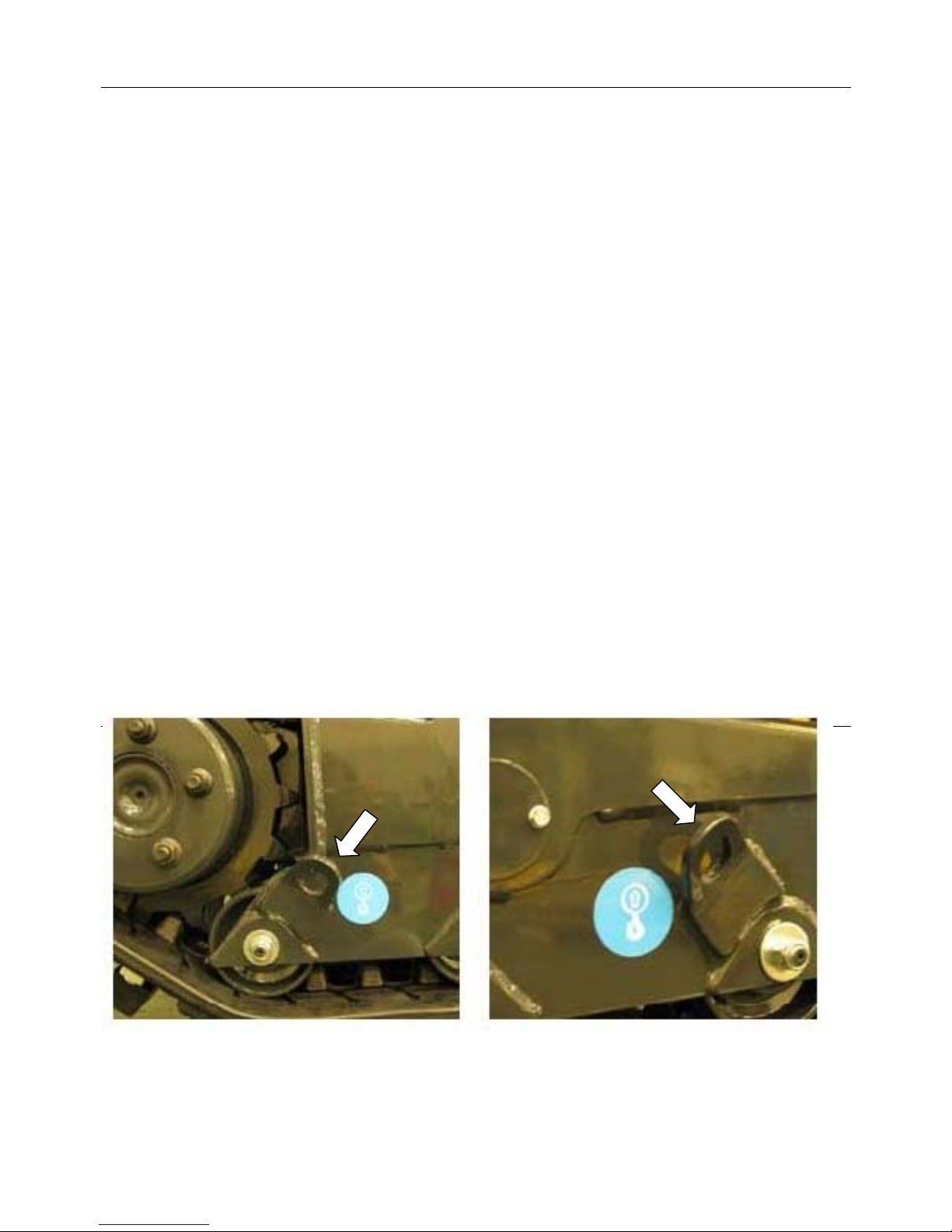
The photos below shown the machine’s lifting points; the lifting eyes are located at each end of
the track plates on both sides of the machine. The positions of the lifting points enable the
machine to be safely raised using suitable overhead lifting equipment.
Note: All equipment used to raise the machine must have a SWL in excess of the total weight of the
machine – keep all persons at a safe distance from the machine during the lifting procedure.
Page 18
9
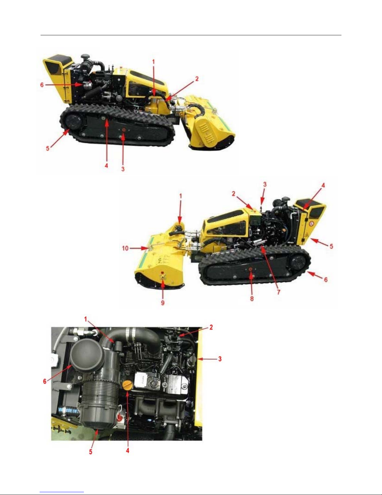
MACHINE OVERVIEW – Component Identification
◄ Right Side View
1. Oil Tank
2. Diesel Fuel Tank
3. Track Tensioner Access
4. Track Roller
5. Drive Wheel
6. Alternator (12V)
Left Side View ►
1. Hydraulic Motor
2. Electrics
3. Warning Beacon Mount
4. Water / Oil Radiator
5. Conveyor & Radiator Guard
6. Rubber Tracks
7. Electric Actuator
8. Track Tensioner Access
9. Lubrication Point
10. Hydraulic Ram (Front Hood)
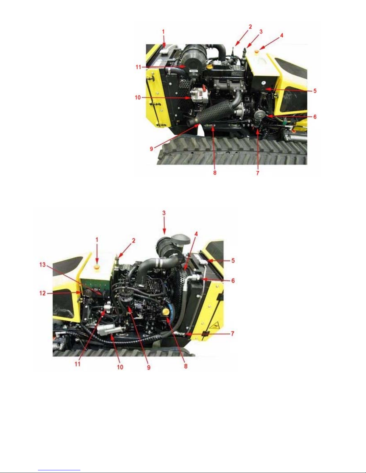
◄ Engine Top View
1. Air Filter Clogging Sensor
2. Radio Control Antenna
3. Warning Beacon Mount
4. Engine Oil Filler Plug
5. Air Filter
6. Air Filter Breather
Page 19
10
Engine Right Side View ►
1. Radiator Filler
2. Radio Control Antenna
3. Warning Beacon Mount
4. Emergency Stop Switch
5. Electric Plug for Services (12V)
6. Horn
7. Electric Compressor
(Self-Cleaning Radiator Fan)
8. Ant-vibration Engine Support
9. Exhaust Pipe
10. Alternator (12V)
11. Air Filter
◄ Engine Left Side View
1. Emergency Stop Switch
2. Warning Beacon Mount
3. Air Filter
4. Radiator Fan Guard
5. Radiator Filler
6. Oil Cooler Input
7. Oil Cooler Output
8. Engine Oil Filler Plug
9. Secondary Fuel Filter
10. Electric Actuator
11. Electric Pump
12. Temperature Gauge
(Engine Coolant)
13. Ignition Key
Page 20
11
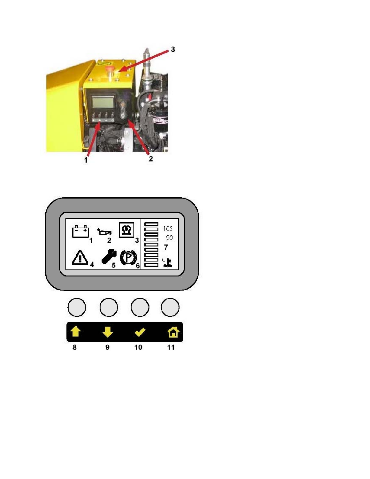
Ignition Panel Components
1. Display LCD
2. Ignition Switch
3. Emergency Stop Switch
Display LCD (CANBUS)
1. Alternator
2. Engine Oil Low Pressure
3. Pre-heater (optional feature)
4. Engine Stop
5. Service
6. Parking Brake
7. Water Temperature
8. Page Up
9. Page Down
10. Enter
11. Home Page (Screen)
Page 21
12
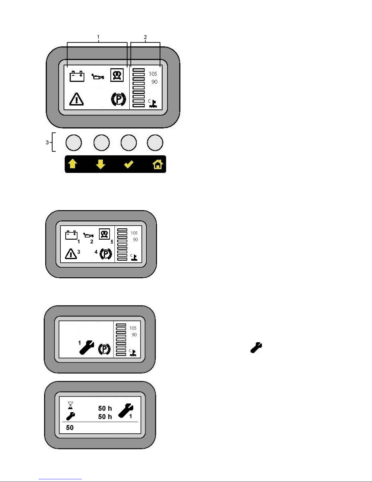
Display LCD - Features & Functions
Area 1. - Warning & Error Codes
Area 2. - Coolant Gauge
Area 3. - Menu Access Buttons
Home Screen
Insert ignition key and turn clockwise to the first position; the display will switch on showing the
‘home screen’. The features displayed will be as shown below;
1. – Battery / Alternator Warning
2. – Engine Oil Pressure warning
3. – Parking Brake Warning
4. – Engine Stop
5. – Pre-Heat Plugs (*)
(*) Only applicable to machines fitted with optional heater plugs.
Service Menu
The service screen displays the number of hours the
machine has been used and the number of hours
remaining before the next service is due.
The service warning symbol will be displayed when
the pre-set service interval has been reached, the
machine must now be serviced, (refer to maintenance
section for details), and the service counter reset.
When the correct service work has been performed
contact McConnel Service on +44 (0)1584 875 848 to
obtain a 4 digit code needed to reset the counter.
Note: the service warning symbol will continue to flash
each time the engine is started until the service
counter has been reset.
Page 22
13
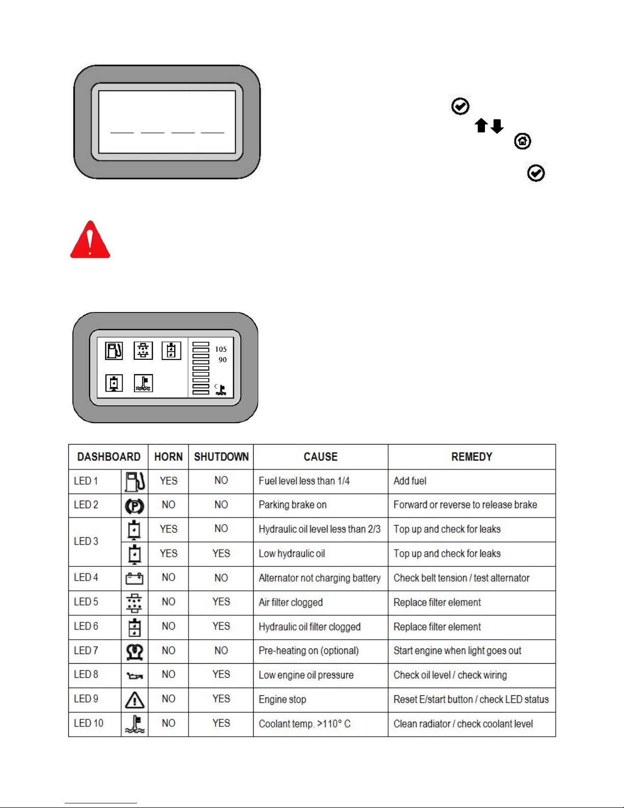
Service Code
Once the required service has been performed, the
procedure for resetting the counter is as follows;
1. Press and hold the enter button for 3 seconds.
2. Enter 4 digit Service Code using the buttons
to select the numbers, and the home button
to scroll from left to right.
3. Confirm the entry by pressing the enter button
The 4 digit service reset code is available from McConnel Service on: +44 (0)1584 875 848
CAUTION! Entering a service code without performing the correct scheduled
maintenance will void machine warranty.
Warning Symbols
Page 23
14
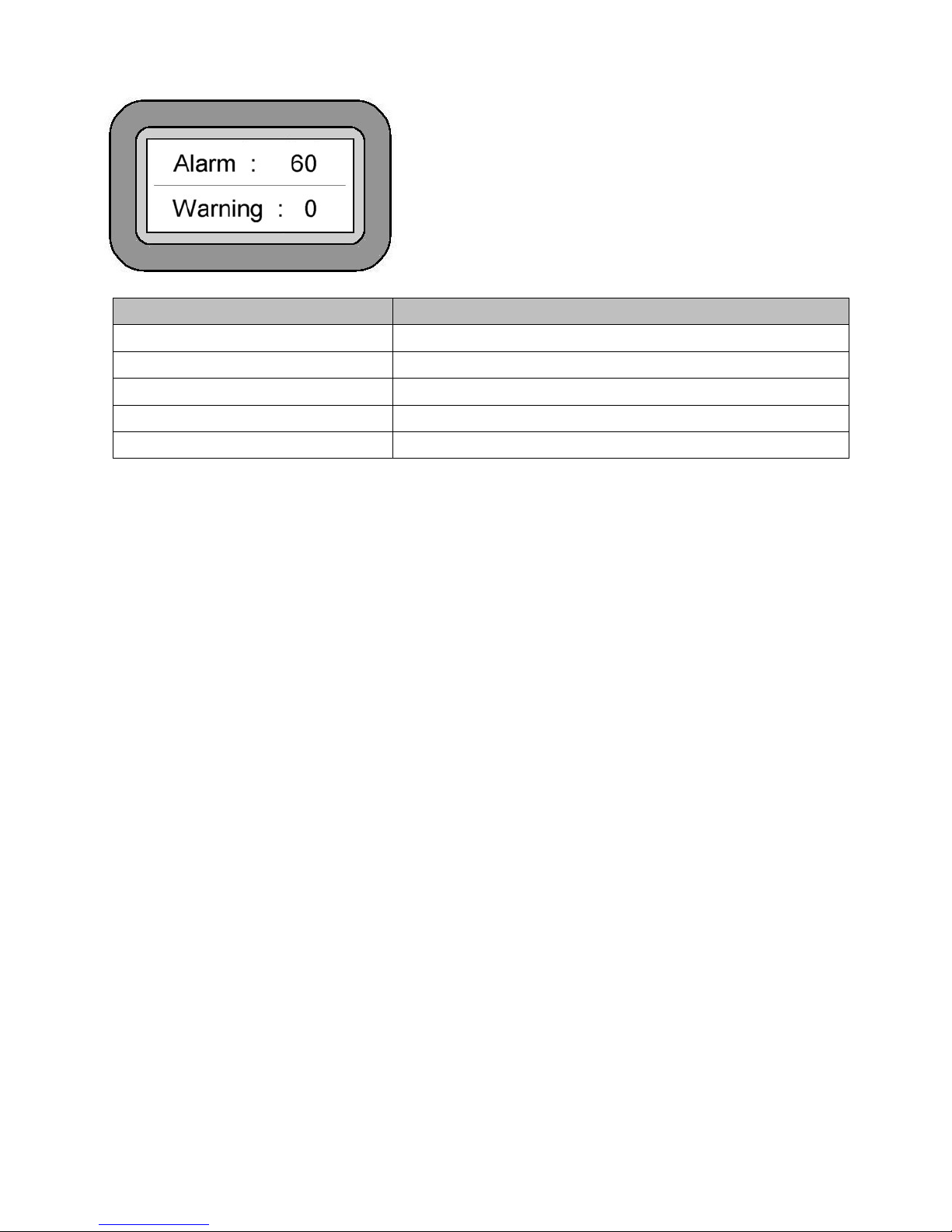
Alarm
In the case of a failure or malfunction the screen will
display ‘Alarm’ and a numeric error code to identify the
component that has malfunctioned.
Refer to the chart below for identification of the source
of the fault and report it to McConnel Service if the
problem persists.
Error Code Cause
Set 4 + number Error / Failure - Display
Set 6 + number Error / Failure - Remote Control Communication
Set 7 + number Error / Failure - Joystick
Set 9 + number Error / Failure - Level Sensor
Set 50 + number Error / Failure - Output CPU
Page 24
15
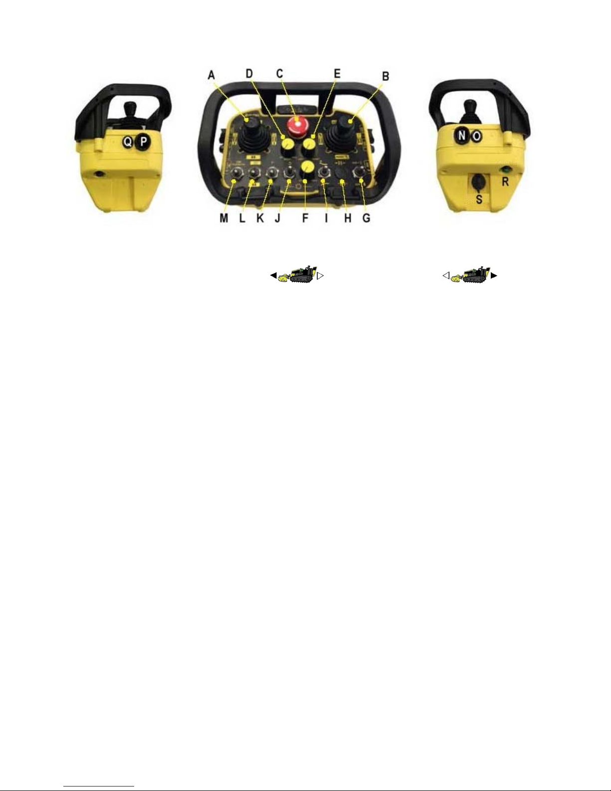
Radio Control Unit – Control Locations & Functions
A. Left Joystick
▲ ▲
Drive (Forward) O Default O Drive Swap Mode
Drive (Reverse) switch L activated
B. Right Joystick
Steering (Left / Right) ◄O►
Flail Head (Up / Down)
C. Power ON / Emergency Stop Button
D. Speed Control
E. Steering Bias
F. Flail Head Pump Control (Rotor Speed)
G. Auxiliary #1
H. Auxiliary #2
I. Front Hood
J. Rotor Direction Selector
K. Gear Selector
L. Direction Swap
M. Fan Reverse Control (Radiator Self-Clean)
N. Engine Stop
O. Engine Start
P. Engine Revs (+)
Q. Engine Revs (-)
R. Connection / Horn
S. S-Key (Codified Key)
Page 25
16
STARTING THE ENGINE
Before attempting to start the engine ensure you have read and understood the
manual and observe all safety instructions surrounding use of the engine and
machine.
WARNING!
Engine must only be started in open air, never in an enclosed environment.
Before Starting
Observe all Safety Instructions.
Ensure machine is in the open air and not in an enclosed environment.
Check fuel level and replenish if required.
Diesel Engine Starting
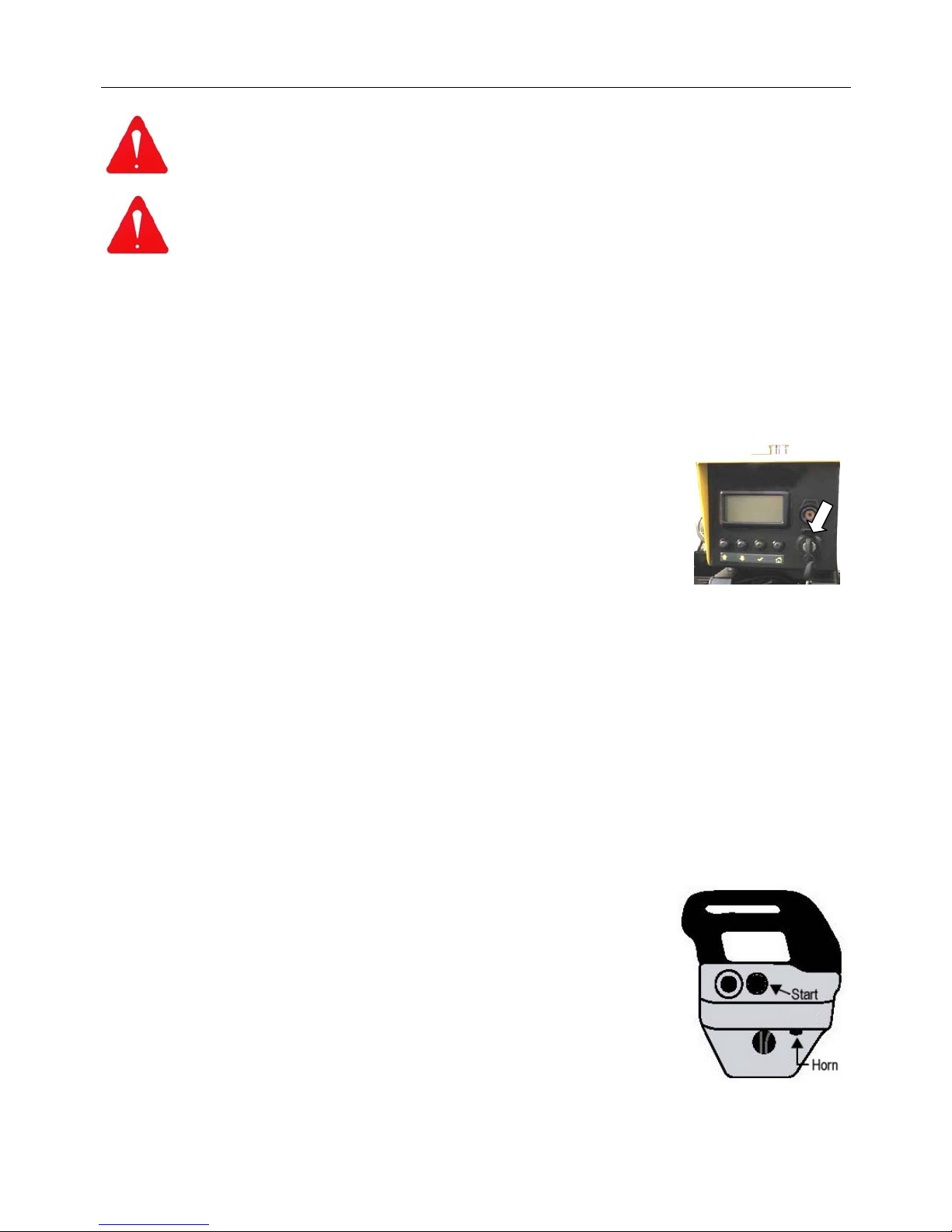
Turn ignition key on the machine clockwise to the first position.
NOTE: the machine will initially perform a sequence of system checks.
On machines equipped with the optional heater plugs, the pre-heat
plug light on the ignition panel will illuminate - wait for the light to go
out before continuing.
Start engine by a further turn of the ignition key or by using the remote control.
NOTE: When the engine is started using the key on the machine’s control panel it is not possible to link to or
operate with the Remote Control Unit. Starting the engine using this method is for running of the engine
and/or using the Emergency Manual Control Unit.
Diesel Engine Starting for Remote Operation
In order to operate the machine remotely the control unit and the machine must first be ‘linked’
so that command signals can be transmitted and received; the procedure is as follows;
NOTE: Ignition key on the machine must be turned to the pre-starting position.
Turn on the control unit by rotating the Emergency Stop Button clockwise – the button will
‘spring out’ to the ON position.
Press and hold the horn button – the unit will search for the
machine’s transmitter and lock onto the signal, the horn will
sound to confirm that the units have linked. Release the horn
button as soon as the confirmation sound is received.
The machine can now be started by operation of the start button
on the remote controls – release button as soon as the engine
starts.
NOTE: If the engine fails to start within 5 seconds release the
button and wait for a minute or so before trying again.
GENERAL CAUTION!
Never operate a starter for excessive uninterrupted periods attempting to start an engine as this can damage
or burn out the starter motor.
Page 26
17
DRIVING & MANOUEVERING THE MACHINE
Operation of the machine must only be performed by a responsible person who
has read the manual and is familiar with the machine controls and all aspects
relating to its safe use.
It is advisable that all new operators practice using the machine, without the
cutting head running, in a safe open area in order to familiarise themselves
with the controls and movements of the machine.
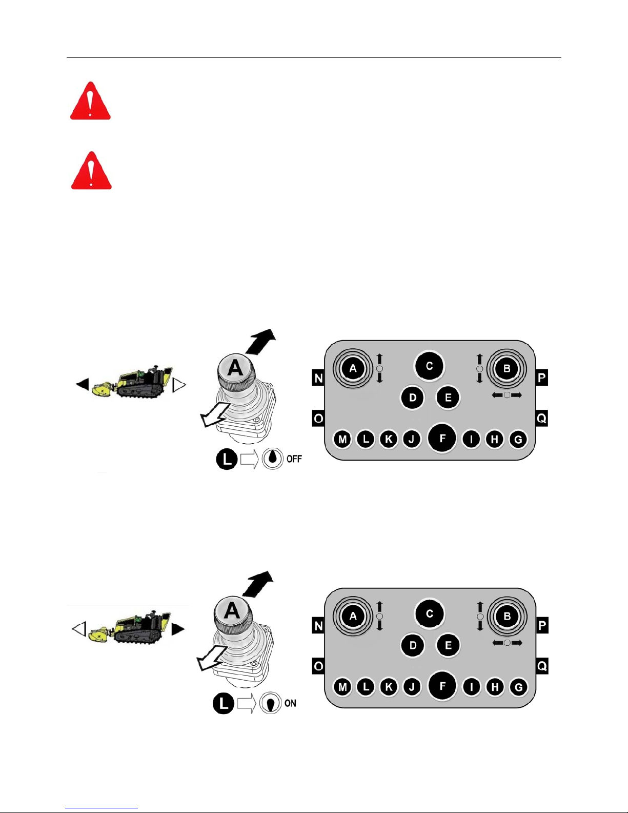
Forwards & Backwards Travel (Default Mode)
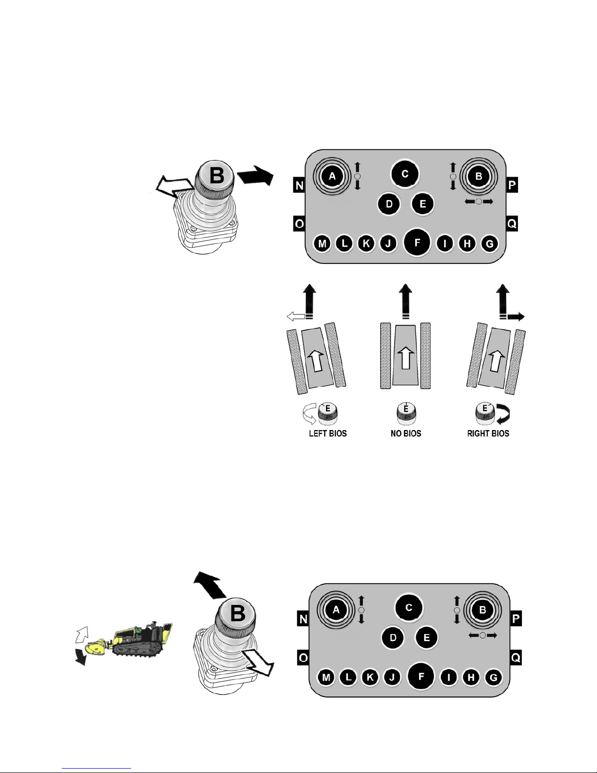
Operation of the machine’s forward and backwards movements are controlled by using the lefthand joystick (A) on the remote controls; push the lever forwards to move the machine forwards,
pull the lever backwards to move the machine backwards. The joystick operates proportionally,
therefore; the further the lever is moved the faster the machine travels. The maximum speed
available will be determined by gear and potentiometer settings, switch ‘K’ and dial switch ‘C’,
details of which are in the following pages.
Forwards & Backwards Travel (Direction Swap Mode)
Direction Swap Mode is selected by activation of switch ‘L’; this swaps the machines direction of
travel on operation of joystick ‘A’. The primary function of this feature is for ease of operation
when the machine’s particular work tool is ‘rear mounted’ type and requires the machine to be
operated in reverse.
Page 27
18
Steering Direction Control
The steering direction of the machine is controlled by sideways operation of the right-hand
joystick (B); moving the lever to the right will steer the machine to the right and moving the lever
to the left will steer the machine left.
Steering is achieved by adjusting the speed or the turning direction of the tracks in relation to
each other; depending on the intensity of the turn one or other track will decelerate, stop or
even reverse causing the machine to change direction, the sharpness of the turn is relative to
how far the operation lever is moved.
Steering Bias
The steering bias feature allows a degree
of ‘steer’ to be pre-set for operating the
machine across slopes, adjustment is
made using the dial switch ‘E’; rotate the
dial either clockwise or anti-clockwise for
right or left bias respectively, the further it
is rotated the greater the bias. Although
steering will still need to be monitored
and operated as normal it will be to a
much lesser degree.
NOTE: When the machine is operating in ‘direction swapped mode’ (refer to previous page),
steering direction control will be swapped so the steering direction lever continues to operate in
the same left and right manner to match the selected drive direction, the same will also apply to
the steering bias feature.
Flail Head (Tool) Height Control
The tool height is controlled by forward and backwards operation of the right-hand joystick (B);
pushing the lever forwards will lower the tool and pulling the lever backwards will raise the tool.
Page 28
19
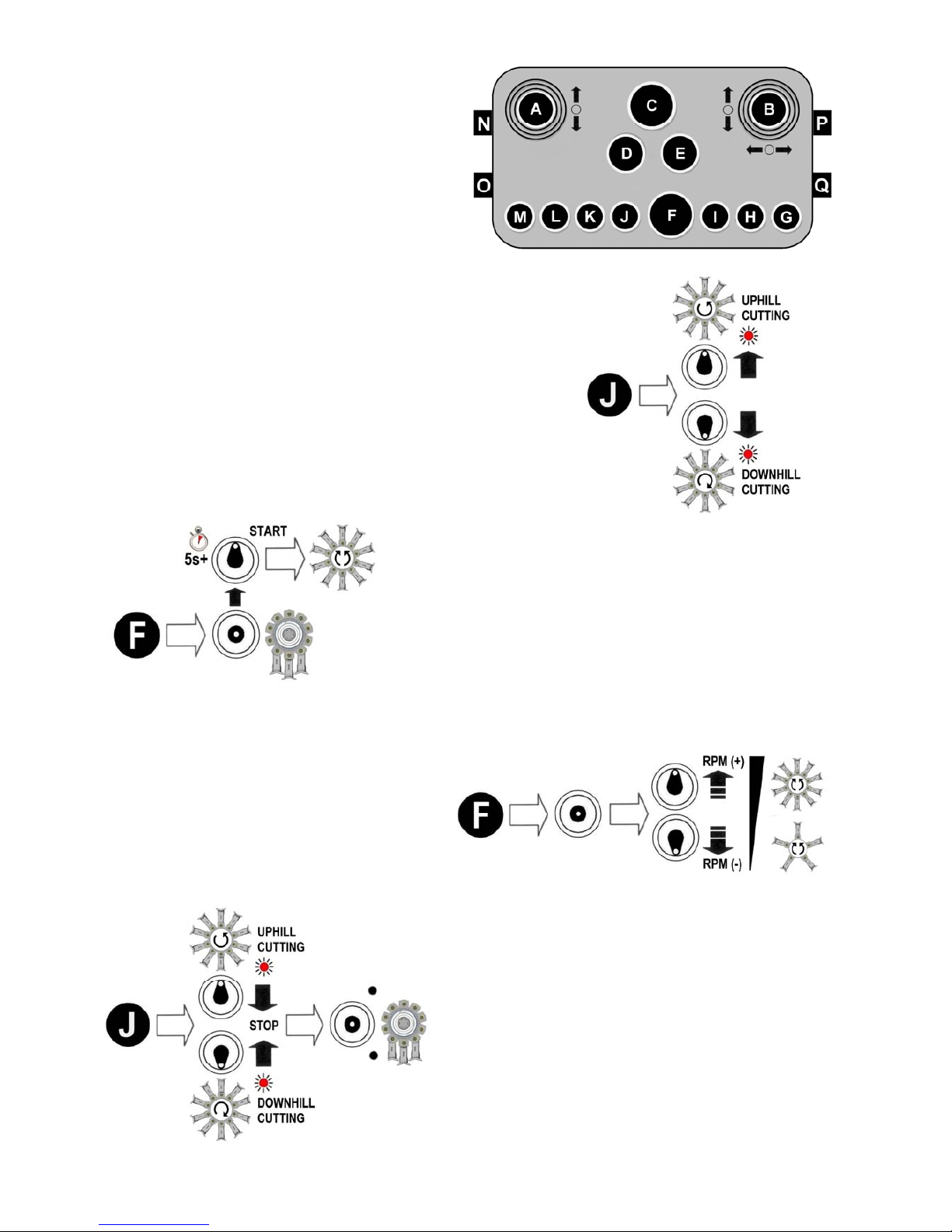
Flail Head Rotor Controls
Operation of the rotor is controlled by using
switches ‘J & ‘F ’. Each of the switch es
performs a dual function; switch ‘J’ is for presetting the rotor cutting direction and for
switching the rotor off, and switch ‘F’ is for
starting the rotor and adjusting its speed.
Refer below for specific details of each
function.
Selection of Rotor Cutting Direction ►
Switch ‘J ’ is for pre-selection of the rotor cutting direction;
move the switch to the up posit ion for uphill cutting or to the
down posit ion for downhill cutti ng - an led light will be
illuminated to indicate the di rection selected. Starting the
rotor is performed by operation of switch ‘F’ – see below.
◄ Rotor Start
Starting the rotor is by operatio n of switch ‘F’; set engine
speed to run at minimum revs before pressi ng the switch
upwards – the switch has a built in time delay to a void
unintentional rotor operation and must be held in pos ition
for at least 5 seconds ; release the switch as soon as the
rotor starts to run. Engine revs can now be increas ed
according to requirements.
Rotor Speed (RPM) ►
Once the rotor is running its speed can be
increased or decreased as required by
subsequent operations of switch ‘F’; eac h
upward or downwar d operation of the
switch will respective ly speed up or slow
down the rotor by a determined amount.
◄ Rotor Stop
To stop the rotor, first reduce the rotor speed to its
minimum using switch ‘F’ as des cribed above, then
move Switch ‘J’ into the central ‘off’ position.
Note (Pre-June 2015 machines only);
In an emergency situation the rotor can be stopped
by use of the Emergency Stop Button ‘C’; this will
immediately switch off and deactivate all machine
functions completely, including the engine.
This feature is not applicable to later machines.
Page 29
20
Flail Hood Control (Machines Operating with Flailhead Attachment)
The flail head is equipped with hydraulically operated front hood allowing the operator to
remotely adjust its opening position to suit differing materials and conditions. The hood, which is
powered by a hydraulic ram, is controlled by up and down operation of switch ‘I’; the switch is
self-centering so operation of the hood in either direction only occurs when the switch is held in
the up or down ‘on’ positions, on release of the switch hood operation stops.
Engine Speed Control (RPM)
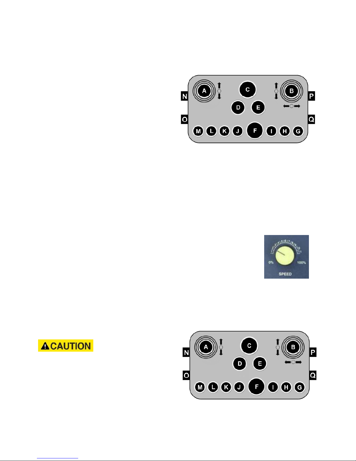
The speed of the engine is adjusted using control buttons ‘P’ and ‘Q’; pressing button ‘P’ will
increase engine revs and pressing button ‘Q’ will decrease the revs.
Gear Control
The machine has 2 gears to provide a choice of travel speeds; in addition to the gear selected
the travel speed will be managed by operation of the travel joystick which itself is directly
proportional to the speed setting of the potentiometer – see below.
When in work it is recommended that the machine is operated in gear 1 and speed limited
especially when working on steep slopes. Gear 2 is primarily for use when driving the machine
between work areas on smooth even terrain where it is safe to use higher speed.
Potentiometer
The potentiometer control (rotational switch ‘D’) determines the maximum
travel speed capability of the machine, from 0 – 100%, when operating the
travel joystick - it is in effect an adjustable speed governor.
Adjustment is by rotating the switch to the required speed (%) position; the
setting chosen will depend on numerous factors but should always be at a
setting that allows the operator optimum control of the machine in work.
Engine Shutdown
Before shutting down the engine all machine movements must be halted, engine revs reduced
to minimum and the rotor switched off. Allow the machine to run at this level for about 1 minute
to stabilize pressures and temperatures - shutting down the engine is then performed by
pressing button ‘N’ which will stall the engine. When the engine has stopped the procedure is
completed by switching off the ignition key on
the machine.
Always turn ignition key OFF after stopping the
engine; failure to observe this risks possible fuel
pump damage due to electric pump overheating.
If the machine is to be left unattended the key
should be removed and control unit and key
placed in a secure safe location.
Engine Start
Engine start from the remote control unit is by use of button ‘O’ – refer to ‘Starting Engine’
section for details of this procedure.
Page 30
21
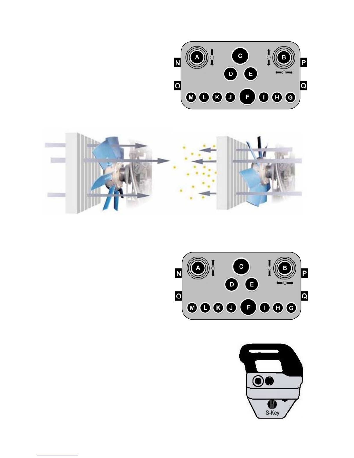
Clean Fix Control
Clean Fix is a built in ‘self-clean’ feature
designed to reduce the build up of dirt and
dust in the radiator matrix; on activation of
the its control switch (‘M’) the blades of the
fan change angle diverting air flow back
through the radiator thus removing dirt and
dust particles.
Although Clean Fix operates automatically
at preset periods, the operator control
allows the user to override the function to
perform additional cleaning cycles when
working in dirty or dustier conditions.
Auxiliary Functions
Switches ‘H’ & ‘G’ are reserved for optional
or additional auxiliary functions that may be
required to operate different attachments
and equipment.
S-Key
The address of the remote control unit is stored in the S-Key and
is matched to the machine it was supplied with, therefore the
controls will only communicate with a specific machine; the S-Key
cannot be removed for use in an alternate control unit and will not
operate a different machine.
WARNING! Do not attempt to turn off or stop a machine by removing the
S-Key; only use the correct commands and procedures to stop and switch
off the machine.
Normal fan operation ▲ Clean Fix activated ▲
– air drawn through radiator for cooling – air blown through radiator for cleaning
Page 31
22
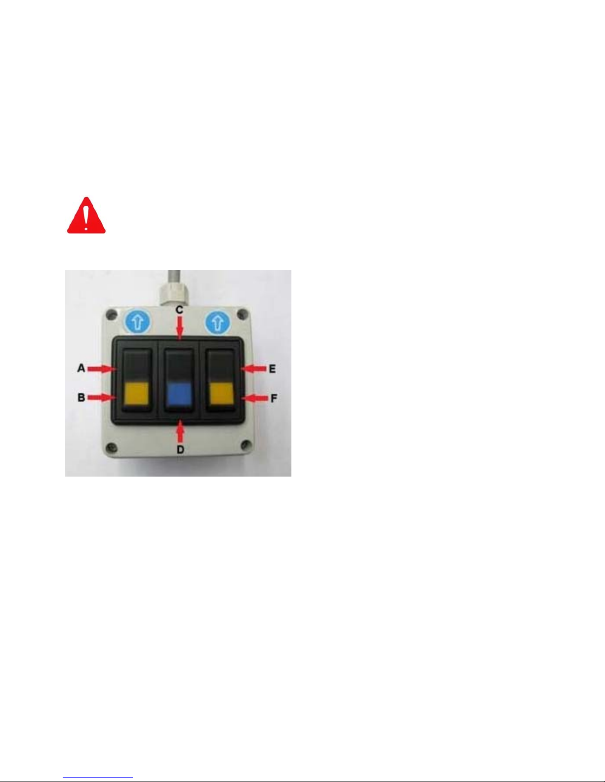
Manual Control Unit (Emergency Track Operation only)
A manual control device for track operation is provided with the machine to allow the operator to
bypass the Radio Controller in the event of a controller malfunction.
When connected to the machine, this devise will allow the operator to raise and lower the
flailhead and manoeuvre the mower in any direction.
This feature is primarily for use in an emergency situation to allow transport of the machine in
the event of a sudden breakdown or for diagnosing an issue with the controller.
When operated in this mode the machine will only travel at minimum speed and all other control
features are deactivated.
To use this control the unit must first be connected to the electronic ignition box, refer to the
following page for details.
WARNING!
The manual track control is for emergency situations and troubleshooting
purposes only – never attempt to use this feature for normal work operations.
Manual Controller
A) Forwards left track
B) Backwards left track
C) Flailhead (tool) lift
D) Flailhead (tool) lower
E) Forwards right track
F) Backwards right track
Manual Controls Operation
To manoeuvre the machine;
Forward travel is by simultaneous operation of buttons ‘A’ & ‘E’.
Right turn is by operation of button ‘A’ only.
Left turn is by operation of button ‘E’ only.
Reverse travel is by simultaneous operation of buttons ‘B’ & ‘F’.
Counter-rotation to the right is by simultaneous operation of buttons ‘A’ & ‘F’.
Counter-rotation to the left is by simultaneous operation of buttons ‘B’ & ‘E’.
Flailhead (tool) lift is by operation of button ‘C’.
Flailhead (tool) lower is by operation of button ‘D’.
Page 32
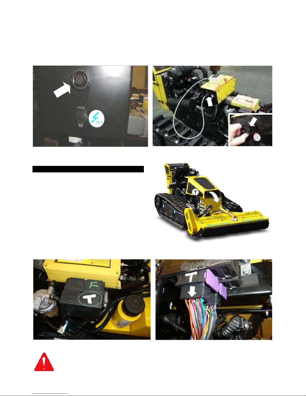
23
Location of Brake Control Module (T)
Converting the Machine for use with the Manual Control Unit
The method of adapting the machine for use with the manual control unit requires attachment of
the Control Unit and deactivation of the Brake Control Module; the procedures are as follows;
Control Unit Attachment
Connect the manual c ontrol unit to its connection poi nt on the elec tronic ignition box, this point
is located on the right hand side of the machine as shown in the photos below.
Deactivating the Brake Control Module
Machine builds prior to Serial No. 011400323 only
Under nor mal operating condit ions when
using the remote control, movement of the
joystick sends a s ignal to the brake system
instructing it to release the brakes.
When using the manual contr ol unit the
brake controller must be bypass ed to allow
the brakes to release, this is achieved by
disconnecting the wiri ng loom from the
brake control module.
The brake control modul e is loc ated under
the bonnet on the right hand side of the
machine – indicated ‘T’ in the photographs
opposite and below.
Note: Failure to disconnect the Brake Control Module will result in the engine
stalling when attempting to transport the machine in Manual Control Mode.
Location of connection point for the Manual Control Unit Remove dust cover and plug unit into the connection point
Brake Control Module identification (indicated ‘T’) Disconnect the wiring loom plug from the Brake Control
Module to allow machine operation with Manual Control
Page 33

24
PRE-OPERATION CHECKS
WARNING! All checks or inspections of the machine should be performed with
the machine parked on firm level ground with the engine switched off and the
starting key removed.
The following checks should be made daily before using the machine;
Check all safety guarding is in good condition and fitted correctly.
Check nuts and bolts for tightness, retighten if required.
Check flail head for damaged or missing flails – replace if required before use.
Check oil, coolant and fuel levels, replenish if required.
Check filters – clean or replace if required.
Check radiator matrix is clean – clear blockages if required using compressed air.
Lubricate machine as per details stated in the maintenance section.
Work and Work Area Precautions
Always ins pect the work area prior to operat ions; check for and remove foreign bodies
such as large stones, metal component, wire and glass etc. which could damage
machine c omponent or be eject ed by the f lail head. Any immov eable obje ct should be
visually marked or avoided.
Ensure the area is c lear of animals and persons. Never manoeuvre the machine into a n
area where you can no longer see it working.
Only work the machine in grass or brus hwood that is within its cutting capabilit y;
attempting to cut materials beyond the machines capability will damage components.
When working on slopes always start at the bottom and work up.
Never run the machine down a slope that is in excess of its track option capability.
Never operate the machine on slopes or ground where there is a risk of overturn.
Page 34
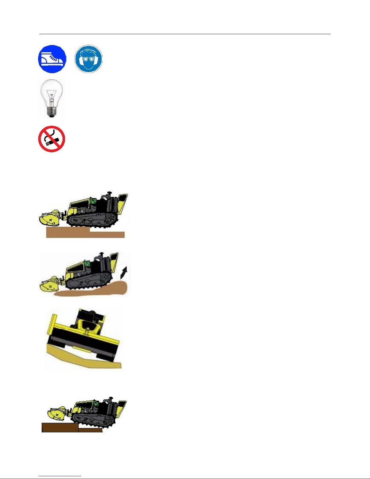
25
OPERATION
Always wear safety shoes, ear defenders and safety glasses when
operating the machine.
Always work in good lighting conditions. If necessary, use artificial lighting in
compliance with local rules in force.
Do not smoke near the machine; oils, fuels and lubricants are flammable.
Before moving the machine, ensure that there are no persons, animals, or obstacles in the work
zone.
Do not change direction whilst moving on kerbs, rocks or
surfaces with considerable differences in height (more than
20cm); in these instances always move perpendicular to the
obstacles.
When reversing uphill, do not steer when transferring from the
level surface to the slope, if this is unavoidable, perform the
manoeuvre gradually.
Do not move along the edge of a slope or on uneven ground with
one track in the horizontal position and the other inclined or
partially raised (when machine is inclined in excess of 10°).
To avoid risk of track damage, always proceed with both tracks
travelling on the same horizontal plane.
When the machine manoeuvres over an obstacle, a space is
created between the bearing rollers and the track - this can
cause the track to come off its seat. The same situation can
occur in reverse when a space is created between bearing roller,
idler roller, and track. To eliminate this risk, track guides are
provided on the front part of the undercarriage.
Page 35
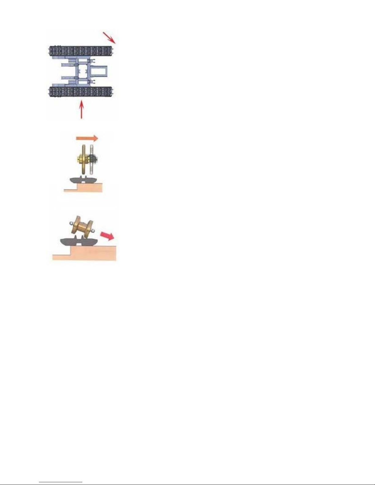
26
If the machines changes direction, and the track cannot move
sideways due to the presence of an obstacle, there is a risk that
the track can be damaged or come of its seat; wherever possible
avoid turning the machine when it is against an obstacle, if
unavoidable, make manoeuvres slowly and gradually until clear of
the object.
◄ If the machine moves in reverse in these conditions, there is risk
of the track coming off its seat.
◄ If the machine is steered in these conditions, the track will come
off its seat.
Page 36
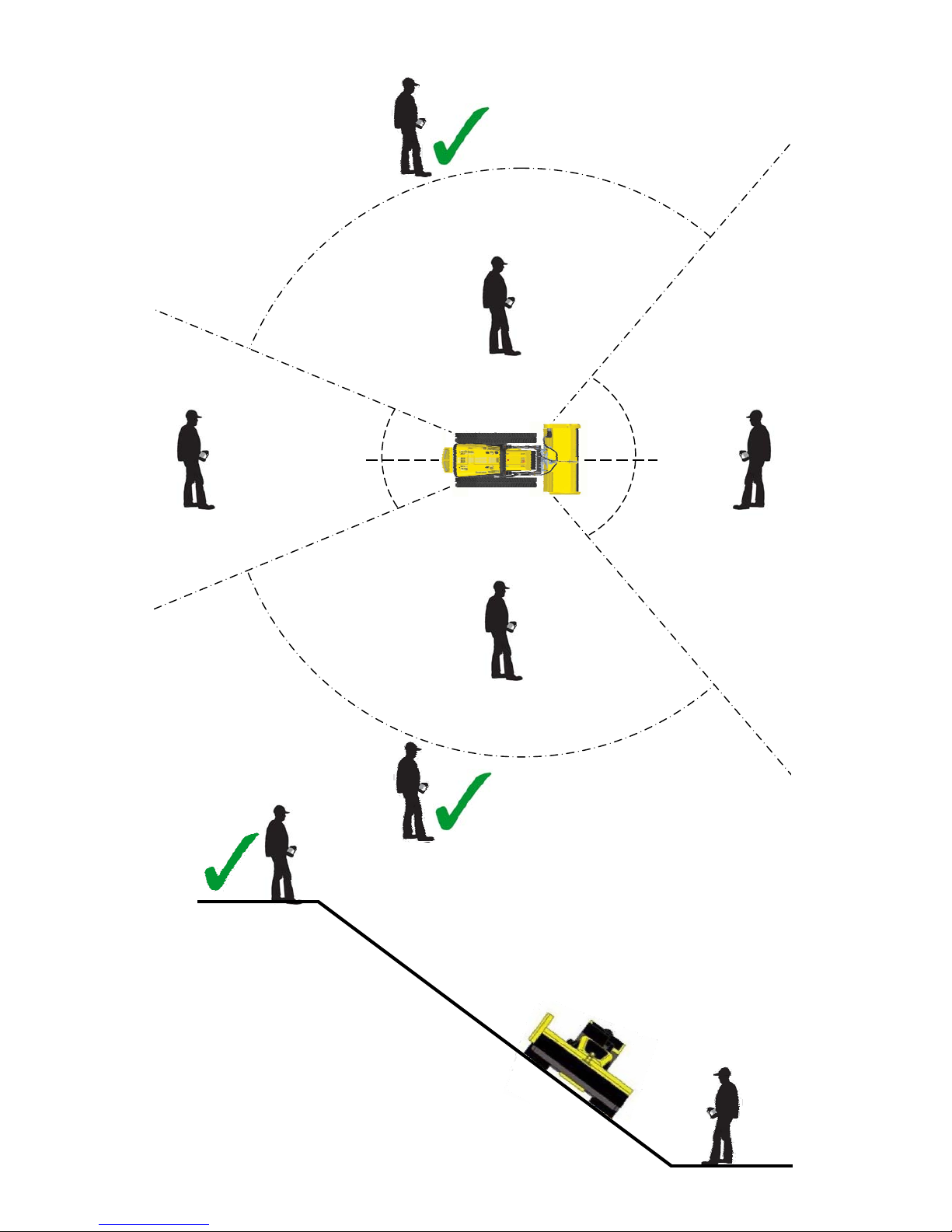
27
X
X
X
X
60°
60°
20°
20°
5m
5m
5m
5m
X
Operating Position & Distance
Slope Working
Page 37

28
MAINTENANCE SECTION
Diesel Engine Maintenance
For specific service and maintenance information regarding the diesel engine, refer to the
engine manufacturer’s handbook provided with the machine. Ensure all service and
maintenance work on the engine is carried out at the intervals stated in that manual.
Maintenance Scheme (General Machine)
After Initial 8 Hours - New Machine
Check nuts, bolts, pipes and hoses for tightness – tighten if required.
Check track tension and adjust if required – refer to specific section for details.
Check hydraulic oil level – replenish if required.
Clean radiator matrix – use compressed air line.
Daily
Clean radiator using compressed air line.
Check primary air filter – Clean with compressed of air if required.
Check hydraulic oil level – replenish if required.
Check engine oil level – replenish if required.
Check coolant level – replenish if required.
Initial 50 Hours - New Machine
Drain and replace engine oil.
Replace engine oil filter.
Replace fuel filter.
Every 50 Working Hours
Grease carrying rollers and sliding rollers.
Check track tension and adjust if required.
Check alternator belt tension and tighten if required.
Every 250 Working Hours
Drain and replace engine oil.
Replace hydraulic oil filter.
Replace engine oil filter.
Replace engine air filter
Every 500 Working Hours
Drain and replace hydraulic oil.
Every 1000 Working Hours
Drain and replace coolant.
Page 38

29
Maintenance Scheme (Track Components)
Daily Checks
Check track tension.
Check condition of gear motors.
Check track condition; replace tracks when there is less than 10mm of tread remaining or
sooner if there are visible signs of deep cuts or cracks.
Check there are no stones or foreign bodies within the tracks, rollers, gears or sprockets.
Monthly Checks
Check oil level in gear unit.
Check rollers are correctly fastened.
Check there is no slack in the bearings.
Six Monthly Checks
Check wear and tear and overall condition of connections, pinions and lower rollers – these
must be replaced when they reach their maximum wear limit; refer to ‘wear limits’ page.
Check brakes are working correctly.
Check all nuts and bolts for tightness.
Periodic Checks
Check brakes and safety warning decals are in good condition.
Make sure the machine is thoroughly cleaned on a regular basis.
Check all fastenings, supports, steel structural parts, welds and pins etc. are in good condition.
Ensure paintwork is kept in good condition.
Lubricate the tracked undercarriage every 20 working hours.
Hydraulic Hoses
Hoses and hydraulic connections should be inspected for signs of wear or damage on a regular
basis, damaged or worn components must be replaced immediately. The working life of
undamaged hoses is approximately six years, they should be replaced after this period.
Recommended Lubricants / Coolant
Always use the recommended lubricants/coolants taken from the chart below or a good quality
equivalent product.
Machine Component Recommended Lubricant
Hydraulic System (Biodegradable) PANOLIN HLP SYNTH E 46
Hydraulic System (Mineral) Q8 ELI 1298 L
Engine MOBIL SUPER 3000 X1 5W-40
Pins / Bushes / Bearings GREENPLEX EP GREASE
Machine Component Recommended Coolant
Cooling System PERMENANT SUPER ANTIFREEZE LF (50% Dilution)
Page 39
30
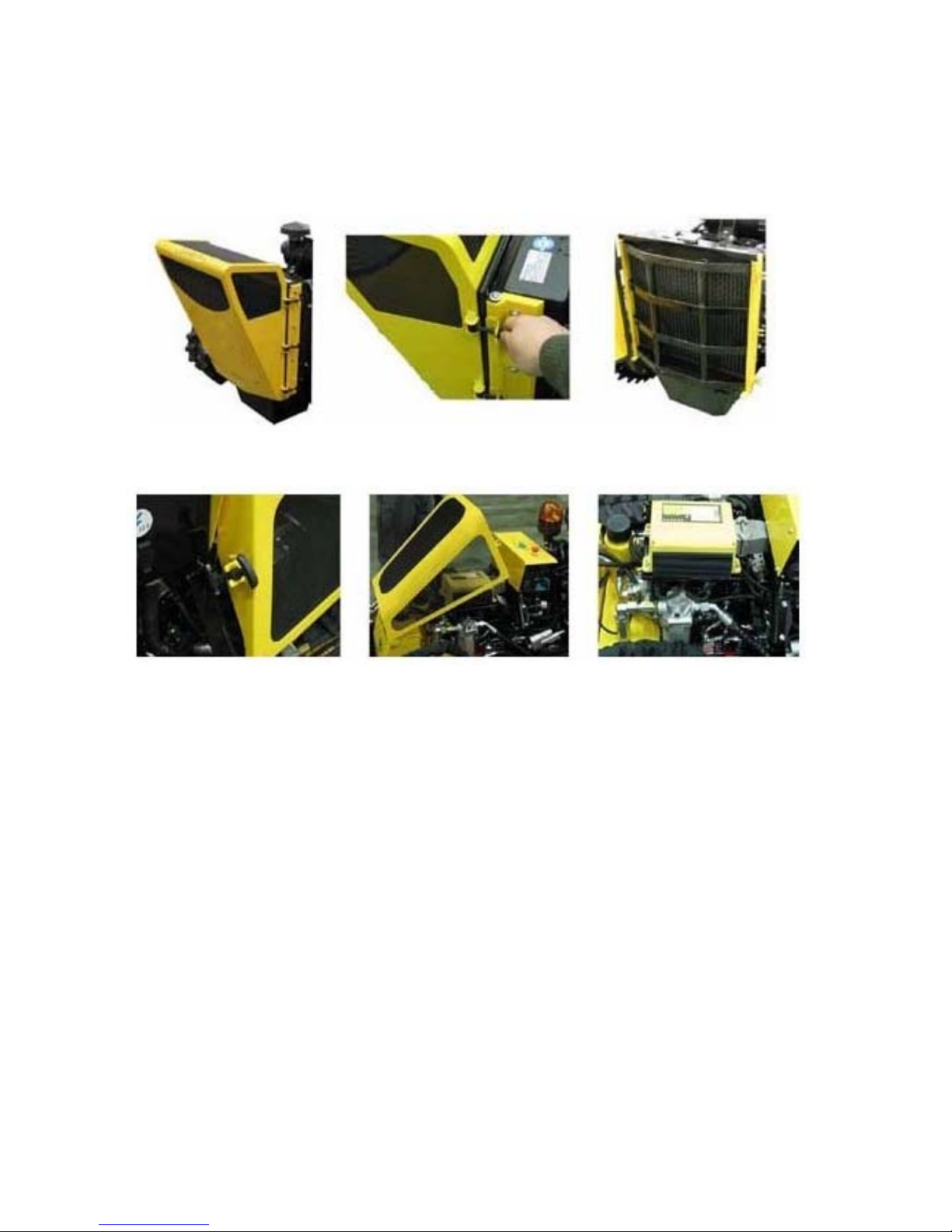
Cleaning the Air Filters Grills & Radiator
If the machine is running, reduce to minimum revs and allow engine to run for a further minute
before switching off – remove and pocket the ignition key.
Clean outsides of air suction grills before releasing the three rubber hooks and opening the
cover. Clean the radiator matrix, inside of the air intake grill and surrounding area using a
compressed air line, do not use any tools to clean the radiator that may cause damage to the
fins. Close the cover and secure in place with the rubber hooks.
Clean air intake grills of the machines front cover to ensure maximum airflow to the engine.
Ensure covers are closed and secured correctly to stop dirt getting in.
WARNING!
If the engine temperature becomes too high a red temperature warning light on the ignition panel
will be illuminated to notify the operator – where this occurs refer to the engine manufacturer’s
manual.
Page 40
31
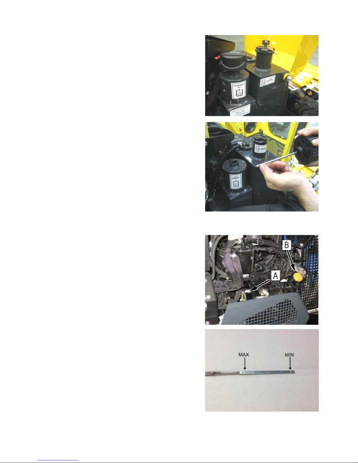
Checking Hydraulic Oil Level
The procedure for checking and replenishing the
machines hydraulic oil is as follows;
Park the machine on a firm level site.
Ensure engine is switch off and the key removed
and pocketed.
Release rubber hooks and raise the front engine
cover.
Unscrew the dipstick (located under the filler cap),
remove and wipe with a clean rag.
Replace dipstick without screwing in, then remove
again and check the level – oil level is correct if the
oil reaches the marker on the dipstick.
If oil level is too low, top up using the correct
recommended oil. Do not overfill beyond MAX level.
When oil level is correct, screw the dipstick back in,
close and secure the engine cover.
CAUTION! Always use the same type and brand of oil for
‘topping up’ of the hydraulic system; never mix different types
and brands of oil.
Checking Engine Oil Level
The procedure for checking and replenishing the
machines engine oil is as follows;
Park the machine on a firm level site.
Ensure engine is switch off and the key removed
and pocketed.
Undo the 4 knurled head screws and remove the
cover.
Remove dipstick (A) and wipe with a clean rag.
Replace dipstick then remove again and check the
level – oil level is correct when the oil level is
between lower and upper marks on the dipstick.
If oil level is too low, top up using recommended
engine oil. The engine oil filler location is indicated
‘B’ opposite.
When topping up oil always clean the surrounding
area of the filler cap before removal to avoid the
risk of dirt contaminating the oil.
When oil level is correct, replace dipstick before
replacing and securing the cover.
Page 41
32
Engine Oil Replacement and Filter Change
Oil Capacity: 6.1L without filter
6.6L with filter
Oil Type: MOBIL SUPER 3000 X1 5W-40
The procedure for changing the engine oil and filter is as follows;
Park the machine on a firm level site.
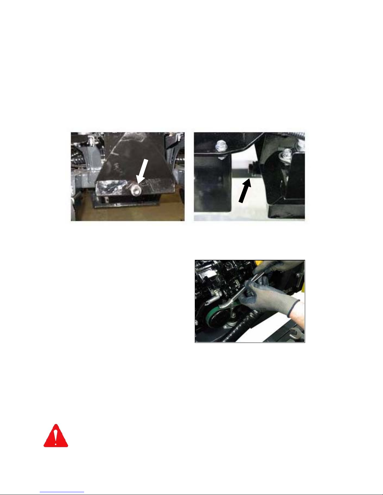
Remove drain plug and release the oil into a suitable container – ensure the container used
has sufficient capacity for the amount of oil.
Once all the oil has been released, replace drain plug and torque to 34.5Nm.
Unscrew and remove the engine oil filter ►
Take the new filter and smear some engine oil on the rubber seal before fitting – screw the
filter hand tight, then turn it approximately a further ¾ of a turn.
Remove filler cap and slowly refill with 6.6L of MOBIL SUPER 3000 X1 5W-40 engine oil.
Replace filler cap and start the engine.
Run engine for 5 minutes or so and stop for a further 3 minutes before checking the oil level
is correct.
WARNING! Used engine oil is both a dangerous waste and a precious raw material;
collect it in a suitable container and recycle it. Never pour waste oil into drains or
waterways – it is both harmful and illegal.
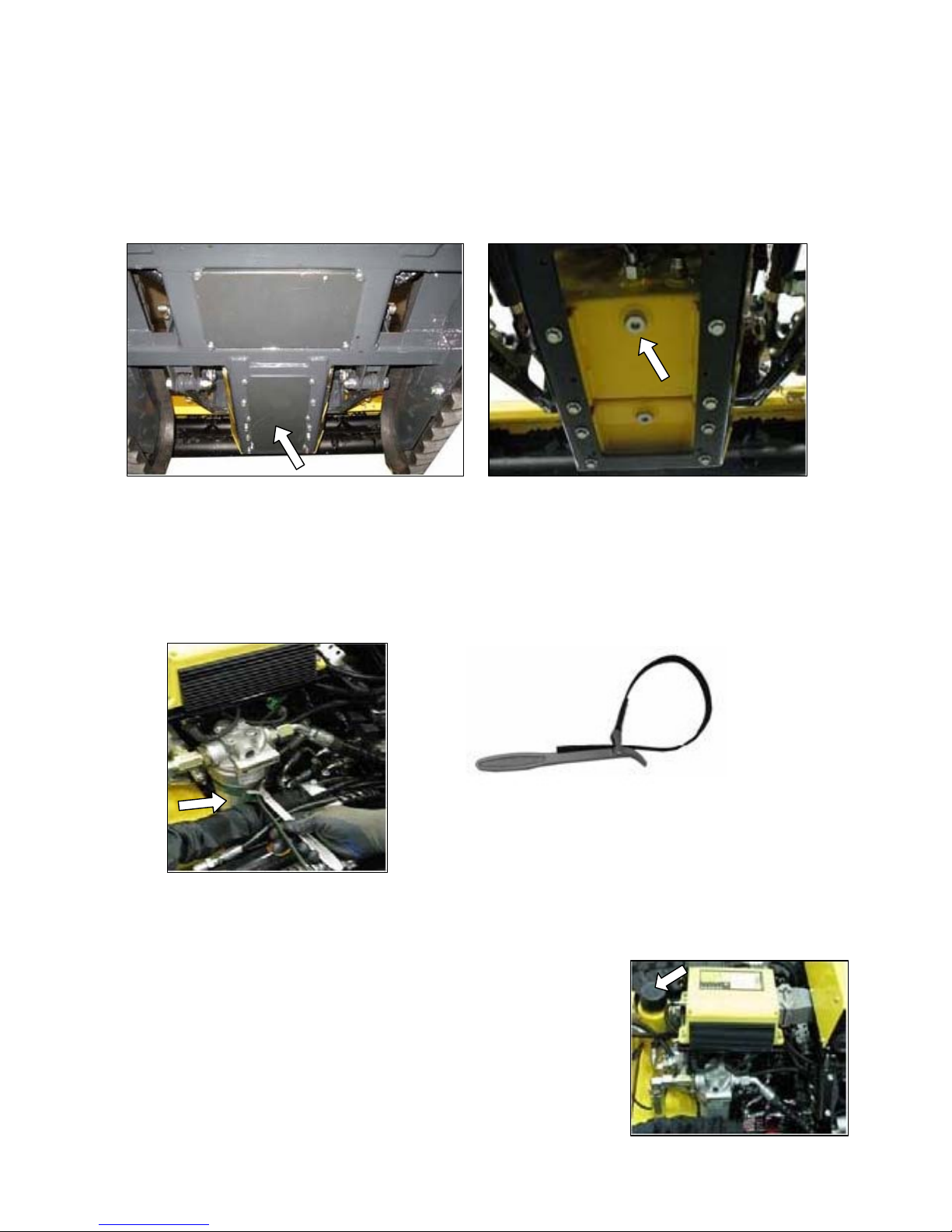
Engine oil drain plug location
Page 42
33
Hydraulic oil tank filler location
Hydraulic Oil Replacement and Filter Change
Hydraulic Oil Tank Capacity: 18 Litres
Complete System Capacity: 28 Litres
The procedure for changing the hydraulic oil and filter is as follows;
Remove the protection plate from the underside of the hydraulic oil tank.
Note: Removal of the plate allows access to both the hydraulic tank drain plug and the fuel
tank drain plug – identify the correct plug before continuing to the next step.
Remove drain plug and release the oil into a suitable container.
When the oil has drained completely, replace drain plug and refit protection plate.
Unscrew and remove the hydraulic oil filter, this is located under the bonnet on the left hand
side of the machine – the filter can be removed by using either a filter wrench or a
hexagonal 19mm spanner.
Fit new hydraulic oil filter and tighten securely – take care not to over tighten.
Note: Always replace filters at the intervals stated in the maintenance schedule using quality
original filters as specified and supplied by the manufacturer.
Refill the hydraulic oil tank with ‘PANOLIN HLP SYNTH 46’
hydraulic oil – check using the dipstick until the level is
correct.
Start engine and allow it to run for 2 minutes.
Stop engine and re-check oil level on the dipstick, top up if the
level has dropped.
Check all components and covers are tightly secured before
using the machine.
Filter Wrench ►
◄ Hydraulic oil filter location
Tank protection plate Hydraulic oil tank drain plug
Page 43
34
Hydraulic Distributor Valve
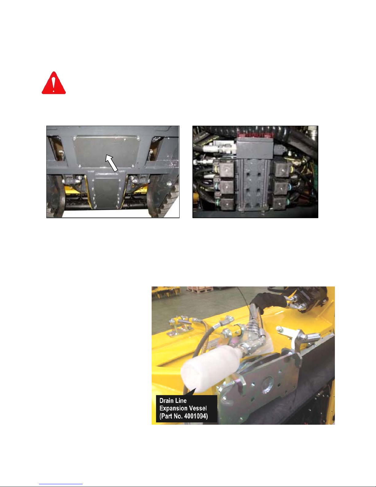
The distributor valve that controls the hydraulic functions of the machine is located under the
vehicle and is only accessible from beneath the machine. When working on this, or any other
item located under the machine, great care must be adopted to ensure the machine is securely
positioned before attempting to access or work on the component.
WARNING: Never attempt to work under any machine that it not safely supported and
chocked using suitable equipment specifically designed for the task and capable of
supporting its weight.
Access to the valve is gained by removal of the protection plate which is held in position by six
bolts.
Expansion Vessel – Flail Head Hydraulic Circuit
Machines are provided with an ‘Expansion Vessel’ to protect the flail head’s hydraulic system
when the head has been removed from the machine. The Expansion Vessel attaches to the flail
head drain line to permit oil escape for protection of the hydraulic motor’s shaft seals.
The ‘Expansion Vessel’ must be
installed on the flail head drain line
at all times when the flail head is
unattached.
Hydraulic valve protection plate Hydraulic distributor valve
Page 44
35
Fuel Filter Cleaning / Replacement
The procedure for cleaning or renewing the fuel filter is as follows;
Park the machine on a firm level site, switch the engine off and open the engine cover.
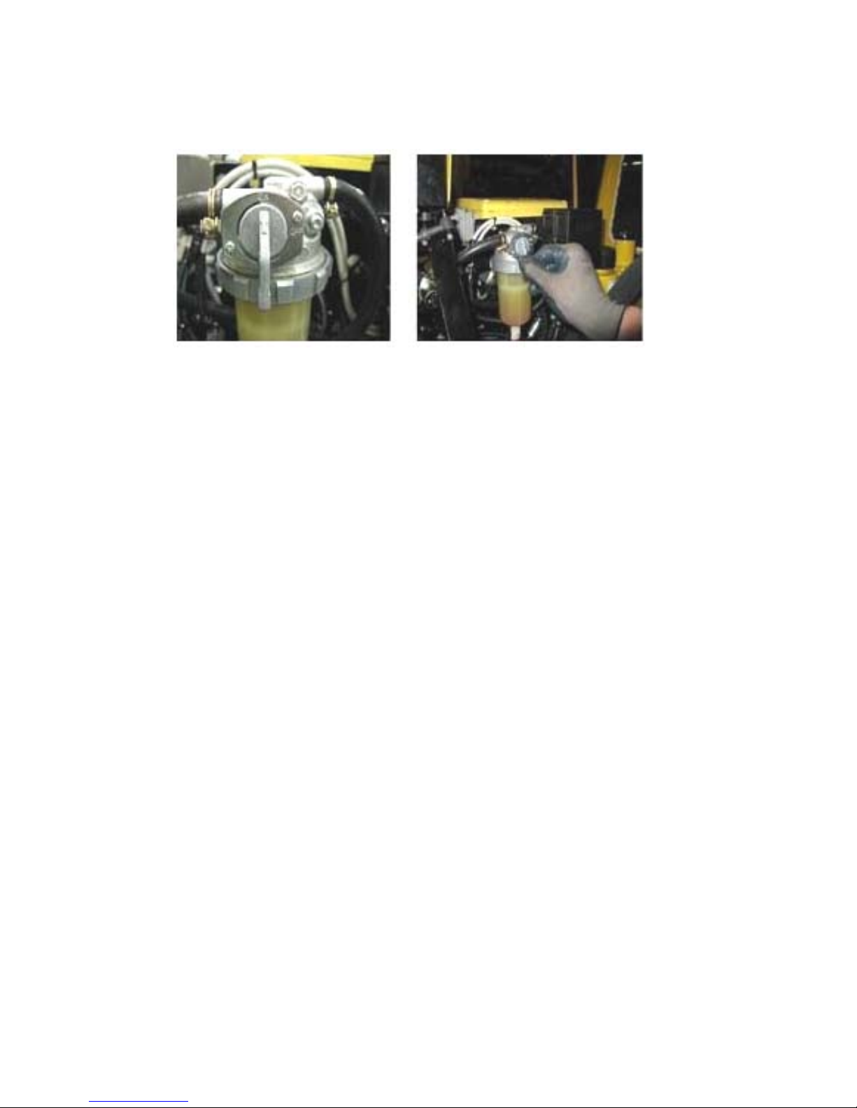
Close the fuel supply tap located on the filter housing.
Place a suitable container under the filter assembly and unscrew the filter bowl securing ring
using a filter key.
Carefully remove filter bowl using the container underneath to catch spilled fuel - retain
sealing ring for subsequent re-attachment.
Remove and clean (or renew) the filter element.
Clean out the inside of the filter bowl using a clean rag.
Re-install the filter and refit the filet bowl ensuring the sealing ring is fitted.
Screw the filter bowl securing ring to a point where the sealing ring seats on the housing and
tighten further third of a turn.
Open tap to restore the fuel supply to the filter.
Unscrew the breather screw on the fuel filter by approximately one turn.
Place a collecting bowl under the fuel filter.
Turn ignition key to position 1, this will switch on the electric fuel pump.
Allow the pump to run until fuel (free of bubbles) begins to flow from the breather screw.
Screw the breather screw back in.
Start the engine.
Check components to ensure there is no fuel leakage.
WARNING: Do not allow the starter motor to run for more than 30 seconds at a time if the engine
fails to start – allow at least 2 minutes before re-starting.
Fuel Filter Fuel Supply Tap
Page 45
36
Fuel Filter Water Drain
Water will accumulate in the filter bowl that will from time to times need to be purged; the
frequency of this task will primarily depend on the quality of the diesel being used. The filter
bowl should be regularly inspected, and water drained off as and when required.
The procedure for draining the water is as follows;
With the engine switched off, place a suitable container under the fuel filter.
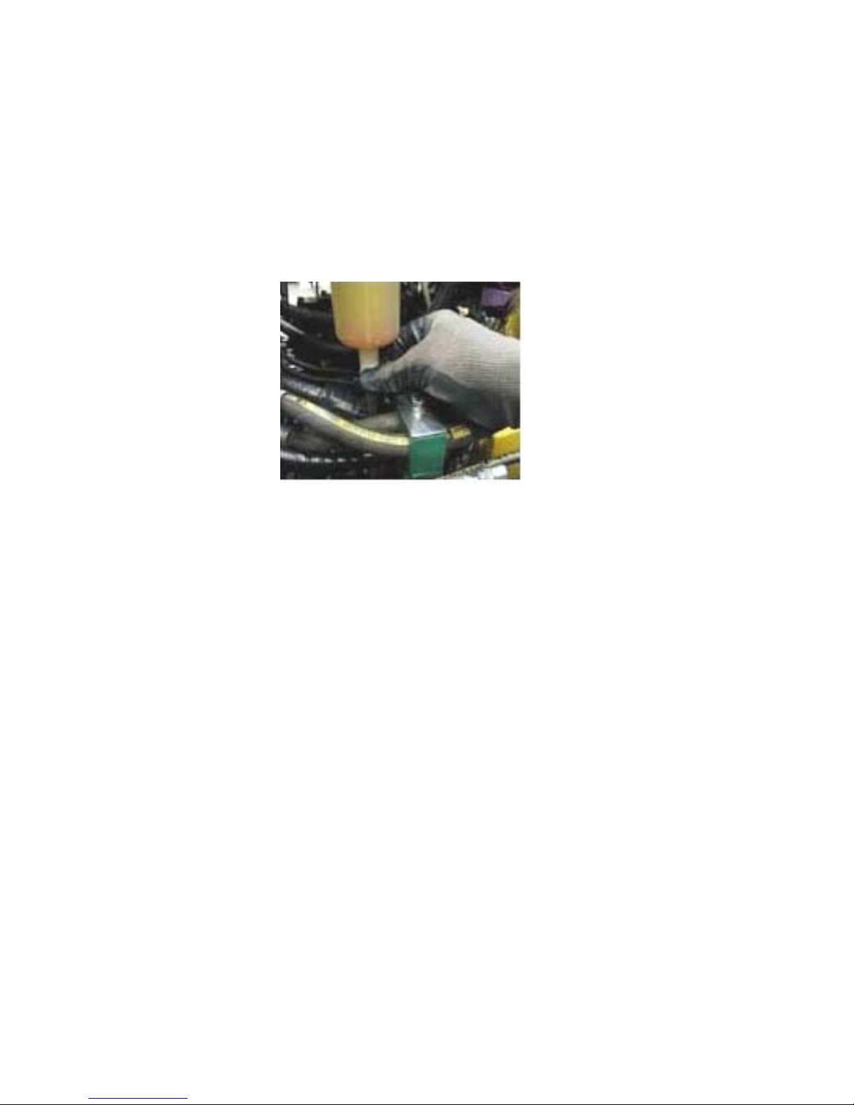
Open the water drain valve located on the base of the filter bowl.
Allow water to run into the container until it is gradually replaced by a flow of fuel.
Close the drain valve.
Priming the Fuel System
If at any time the machine runs out of fuel, it will be necessary to prime the fuel system in order
to get it running again – the procedure for this is as follows;
Fill the tank with fuel.
Unscrew the breather screw on the fuel filter by approximately one turn.
Place a collecting bowl under the fuel filter.
Turn ignition key to position 1, this will switch on the electric fuel pump.
Allow the pump to run until fuel (free of bubbles) begins to flow from the breather screw.
Screw the breather screw back in.
Start the engine.
WARNING: Do not allow the starter motor to run for more than 30 seconds at a time if the engine
fails to start – allow at least 2 minutes before re-starting.
Water Drain Valve
Page 46
37
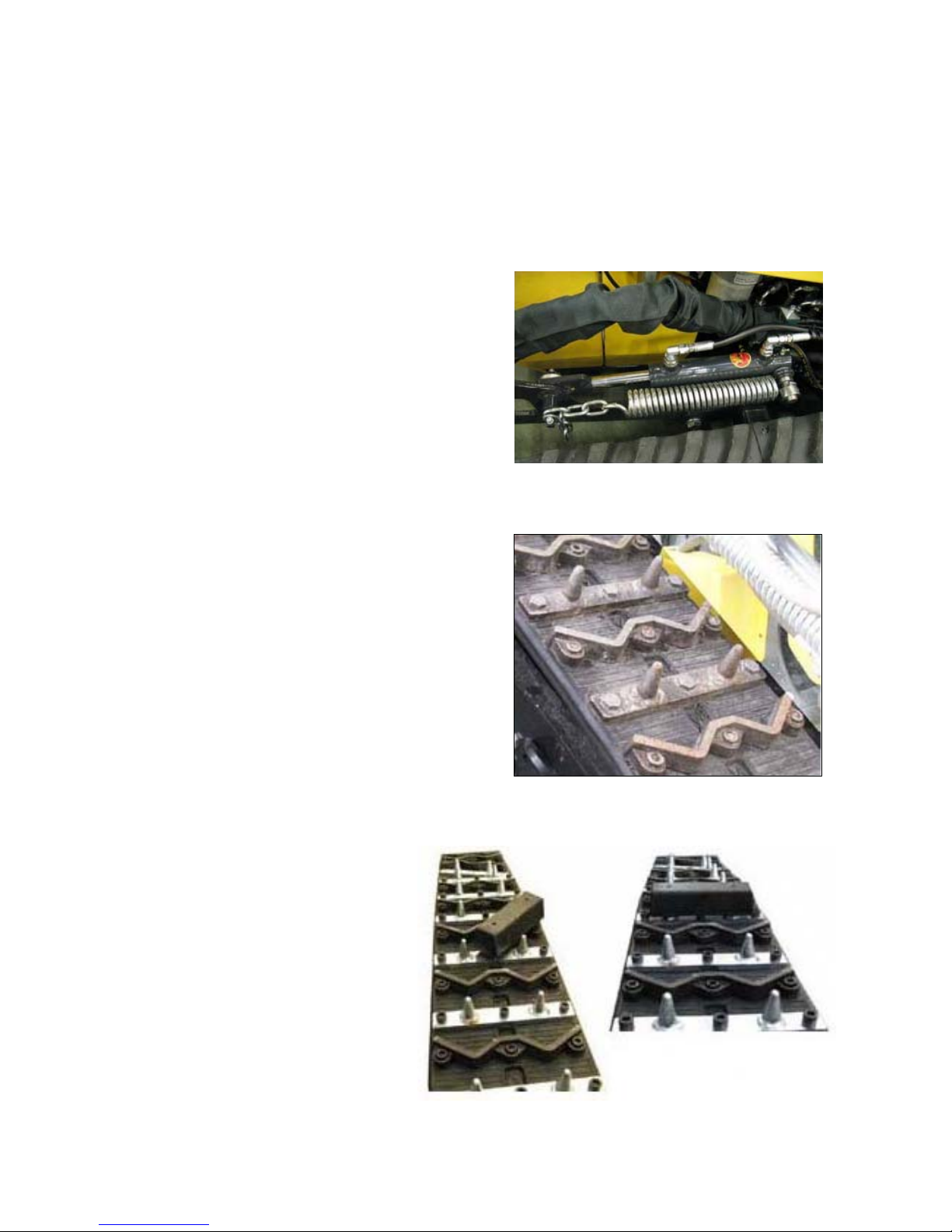
Support Springs
The hydraulic rams that position the front mounted flailhead are equipped with support springs,
the support pressure offered by the springs can be adjusted to suit differing needs and
applications by altering their work position tension. The procedure for adjusting the springs is as
follows;
Raise the flailhead fully by operation of the hydraulic rams.
Remove bolt and washer from the ram rod end and release the chain from the lug.
Re-attach the chain selecting an alternative link to either increase or decrease tension.
Replace washer and bolt to secure in position.
Repeat the process on the opposite ram.
Steel Tracks
Tracks equipped with steel treads can be supplied
as an alternative to the normal all rubber type - the
steel tread version has the additional option of
being fitted with steel spikes.
To fit the spikes remove every second steel tread
by removal of the 3 x M8 Allen headed screws,
and replace with the steel spike treads using the
screws supplied and torque to 70Nm.
If a machine is fitted with spikes the operator must
avoid driving the machine on any surfaces that
would suffer damage from the spikes such roads,
car parks, recreation areas etc. unless the
machine has been fitted with rubber transport blocks specifically designed to protect surfaces.
Transport Blocks Fitment
The rubber transport blocks have
holes in them that locate on the spikes
and are fitted by pushing them onto
each set of accessible spikes before
slowly driving the machine forward so
its weight forces them tightly into
place; repeat the process until all the
spike sets are fitted with a block. After
transportation a lever or large
screwdriver will be required to prise
the blocks back off the spikes.
Page 47
38
Replacing Tracks
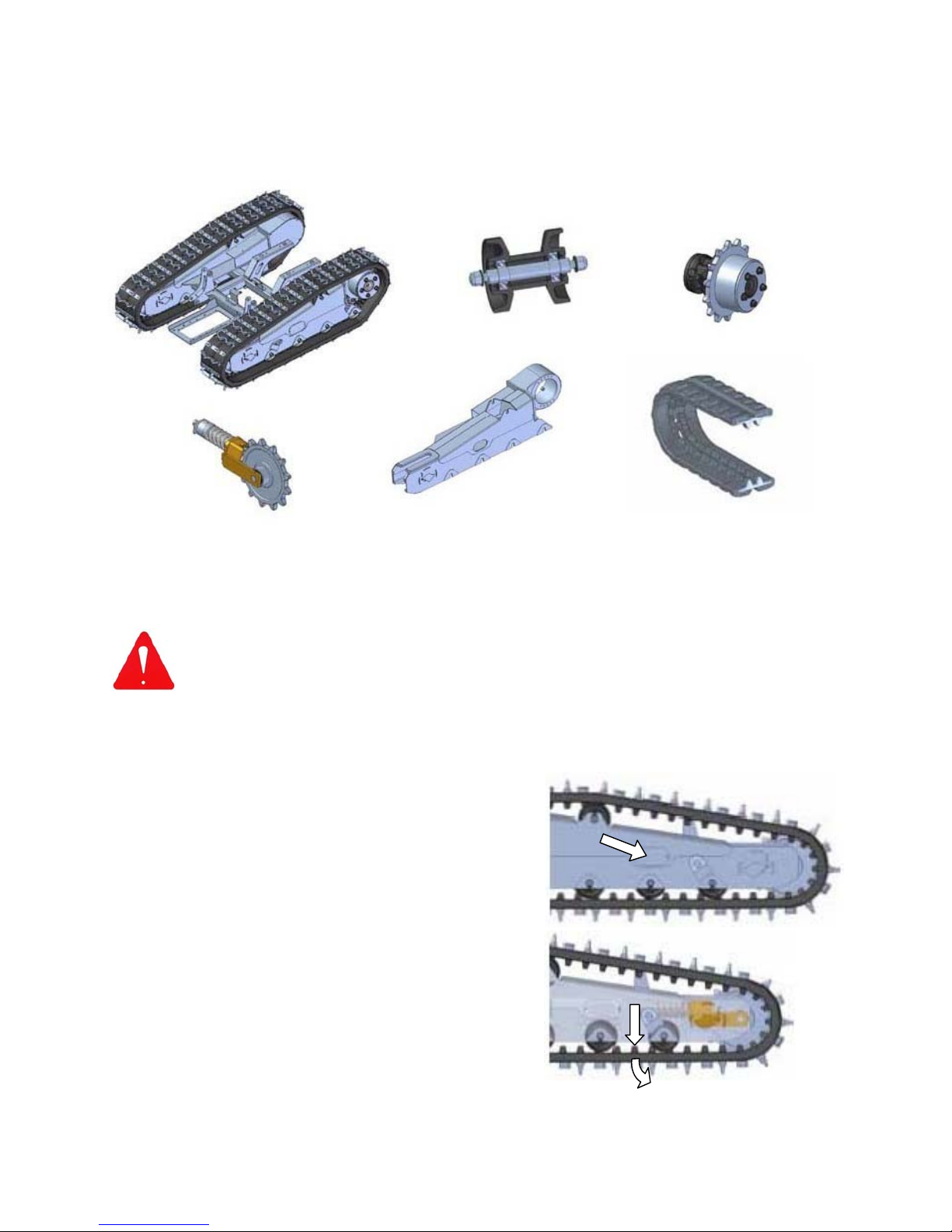
Tracks must be changed when only 10mm of tread remains, or before if they show signs of
excessive cuts or cracks.
The components shown below are constituent parts of the track system illustrated here for
identification purposes.
The procedure for changing the tracks is as follows;
WARNING: Never attempt to work on any machine that it not safely supported and chocked using
suitable equipment specifically designed for the task and capable of supporting its
weight. Ensure suitable safety gear is worn at all times when performing maintenance
tasks. Beware, there is ‘pinch risk’ when working on these components.
Raise the machine off the ground to a height of approximately 30-40cm; ensure the machine
is stable and suitably supported.
Clean undercarriage components and their surrounding area prior to performing
maintenance on them.
Remove backstay side cover ►
Loosen valve on the tensioner unit to release the
grease pressure.
Once pressure has been fully released the valve
can be removed.
Compress the idler roller; this can be done by using
your foot to press the track back.
Draw the track down and outwards at its mid point
on the lower run to pull it off its seating, levering
between the track and the idler roller until it is free
enough to be removed. Take care to keep clear of
the track as it falls to the ground.
Installing the new track is basically a reversal of the above – tension the track by pumping
grease into the tensioner unit to a pressure of 130 Bar. (Max. 150 Bar).
Lower Roller Unit
Sprocket Assembly
Tracked Undercarriage
Backstay
Idler Roller Rubber Track
Page 48
39
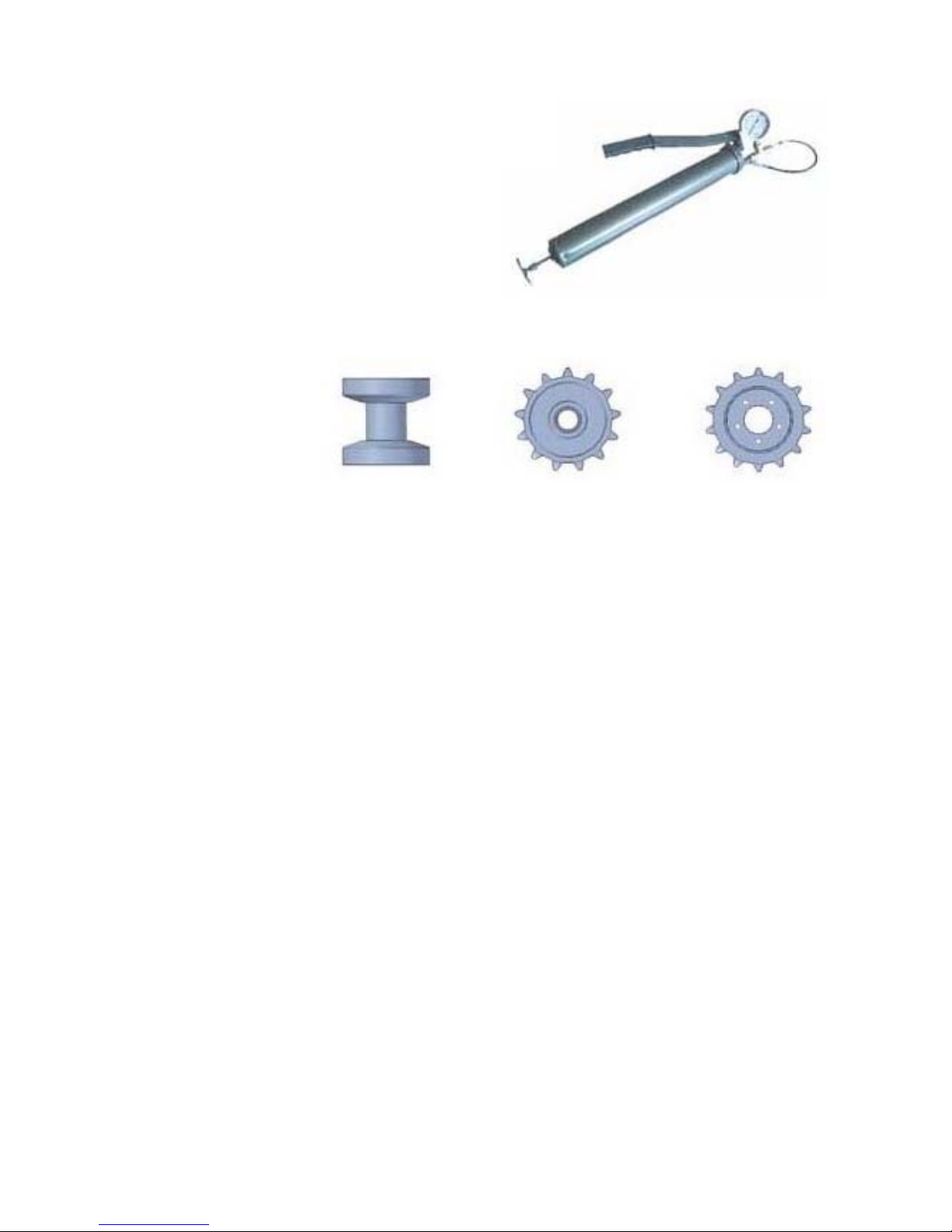
Lower Rollers Front Cogs Drive Cogs
Track Tension Kit (4000271)
Track Tension Kit (Optional)
A grease tensioner system controls the track
tension on the machine. Keeping the tracks
correctly tensioned is an important duty that must
be carried out at the intervals stated in the
maintenance schedule; failure to observe the
correct tension can result in the tracks coming off
the machine during operations.
A Tension Kit, comprising of a grease pump
equipped with a manometer, is available as an
option for use in correctly checking and setting
the pressure. The correct pressure is 130 Bar.
(Max. 150 Bar).
Wear Limits
The track components
shown opposite must be
replaced when they reach
their maximum wear limit,
corresponding to 100% in
the figures stated below;
Ø when new ►
130.0mm 264.0mm 290.0mm
Ø at 25% wear ►
128.0mm 263.0mm 289.0mm
Ø at 50% wear ►
126.0mm 261.5mm 287.5mm
Ø at 75% wear ►
124.0mm 259.5mm 285.5mm
Ø at 100% wear ►
121.0mm 257.0mm 283.0mm
Lubrication of Undercarriage Components
Components of the tracked undercarriage (rollers, pins, bushings etc.), must be greased every
20 working hours.
Page 49

40
UNDERCARRIAGE SPECIFICATIONS
Loading Capacity 1.2T
Length 1548mm
Axle to axle length 1192mm
Track height 479.5mm
Crossmember height (from ground) 150mm
Fixed undercarriage width 1260mm
Number of lower rollers per side (per machine) 4 + 4 (8)
Number of upper rollers per side (per machine) 1 + 1 (2)
Track width 230mm
Number of links per side (per machine) 47 + 47 (94)
Chain pitch 72mm
Track tensioner pressure (Max) 150Bar
Total weight 444kg
Hydraulic motor displacement
332cm³
Hydraulic motor pressure (Max) 190Bar
Hydraulic flow rate (Max) 39l/min
Maximum speed 7km/h
Operating temperature range
-10/+40°C
Maximum operating humidity 95%
Brake release pressure range 12-16Bar
Maximum gradeability 114%
Page 50
41
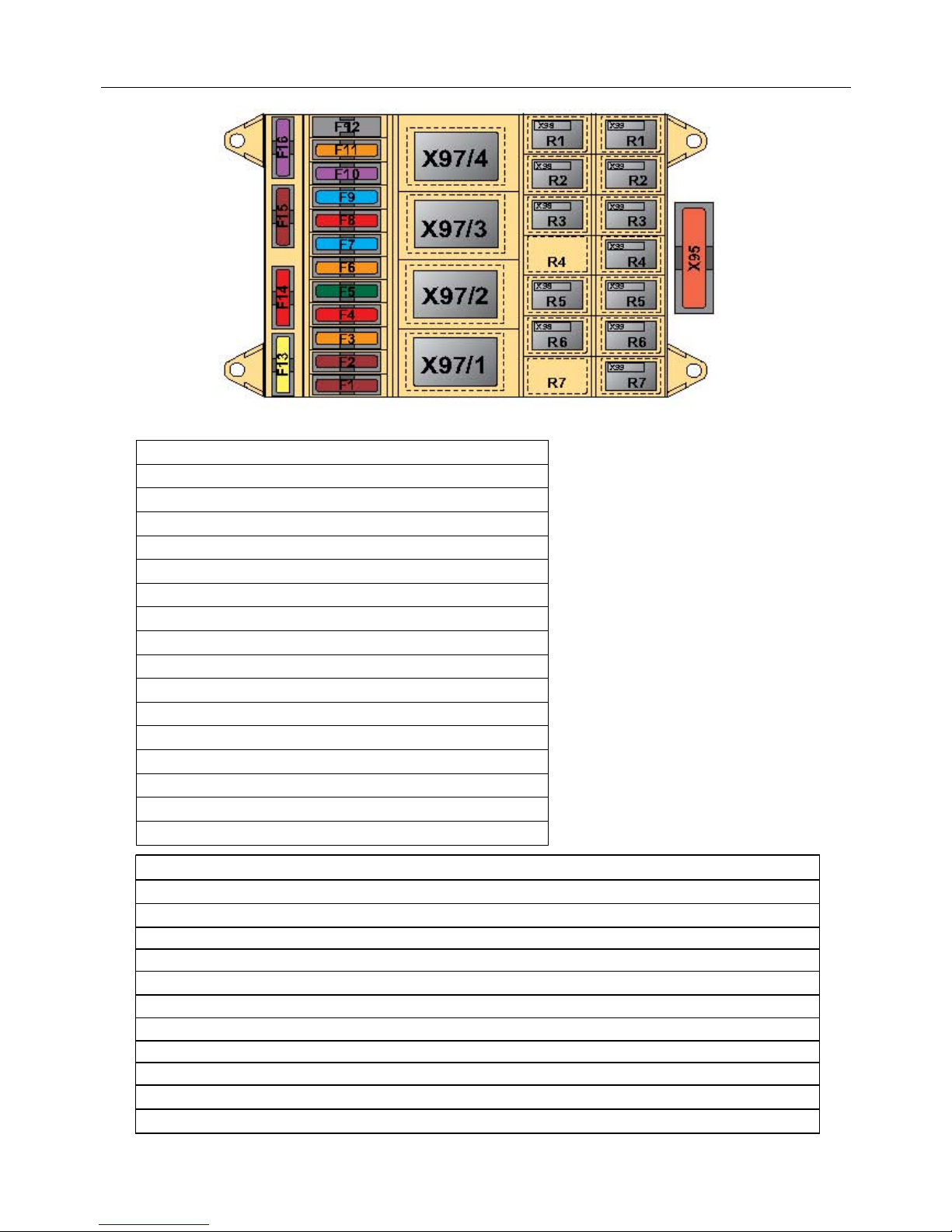
X97/R1 Pull Solenoid relay X99/R2 Manual control
X97/R2 Air Heater (optional) X99/R3 Beacon lamp
X97/R3 Starter relay X99/R4 Clean Fix fan
X97/R4 Battery switch X99/R5 Check test before start
X98/R1 Actuator + X99/R6 Engine oil pressure sensor
X98/R2 Actuator - X99/R7 High water engine temperature
X98/R3 Horn
X98/R4 Free
X98/R5 Lower hyd. oil level
X98/R6 Hold solenoid
X98/R7 Free
X99/R1 Radio-Control stop (Link missing)
ELECTRICAL SYSTEM (Machines Serial No. ROBO071300323 onwards)
Fuses & Relays
F1 Fuel Pump 7.5 Amp
F2 Actuator 7.5 Amp
F3 +15 Controllers & Display 5 Amp
F4 Hold Solenoid + Safety Stopdown 10 Amp
F5 Pull Solenoid 30 Amp
F6 +15 Warnings Relay 5 Amp
F7 Beacon 15 Amp
F8 Horn 10 Amp
F9 Wiring Control 15 Amp
F10 +12V Sensors & Buttons 5 Amp
F11 Alternator 5 Amp
F12 Free
F13 +30 3B6 Controller 20 Amp
F14 +12V Plug 10 Amp
F15 Receiver Fuse 7.5 Amp
F16 +20 Canview Display 3 Amp
X95 General Fuse 40 Amp
Page 51

42
TROUBLESHOOTING
Symptom Possible Cause Solution
Track damage. Excessive tread wear;
Loosening/breaking of internal
structural steel rope.
Replace track.
Track slackens frequently. Faulty tensioner valve.
Damaged tensioner seal.
Worn tensioner components.
Replace valve.
Replace seal.
Replace worn components.
Upper track does not stay in
position.
Track slide worn.
Upper roller worn.
Replace slide.
Replace upper roller.
Lower track does not stay in
position.
Lower track guide worn.
Lower roller worn.
Replace lower track guide.
Replace lower roller.
Track ‘jams’ when the machine
is steering.
Material (stones, rocks, earth
etc.) trapped between rollers,
sprockets, idler roller and track.
Remove material by turning the
track in both directions while
slackening slightly, raise machine
at same time if possible.
Oil leakage Hardened seals.
Gasket/seals damaged or worn.
Clean around component and
recheck after a few days.
Contact dealer.
Excessive noise. Internal malfunction.
Worn seals.
Contact dealer.
Excessive vibration. Internal malfunction.
Worn seals.
Contact dealer.
Overheating Lack of oil.
Arduous conditions/hot climate.
Brakes binding.
Add oil.
Contact dealer.
Check brake release pressure.
Motor runs but gear unit not
working.
Motor wrongly assembled.
Internal malfunction.
Brake jammed.
Check coupling between motor
and gear unit.
Contact dealer.
Check braking system.
Brake not releasing. Lack of brake pressure.
Faulty brake seals.
Check brake connections.
Contact dealer.
Brakes not locking. Residual pressure in circuit.
Worn brake components.
Check hydraulic system.
Contact dealer.
Page 52
1
ROBOCUT
- Parts Manual -
For machines 07/13 onwards
From S/No: ROBO071300323
(Rev. 11.09.17)
Page 53

Page 54

1
LIST OF CONTENTS
Page No.
Parts Section
Chassis Assembly 2
Track Roller Assemblies 4
Track Tensioner Assemblies 6
Rubber Tracks 8
Equipment Mounting Assembly 10
Engine Cover Assembly 12
Radiator Cover Assembly 14
Machine Cover Assembly 16
Roll bar Assembly 18
Diesel Engine 20
Diesel Engine Components 24
Pumps Assembly (Early Machines) 26
Pumps Assembly (Current Machines) 28
Actuator Assembly 30
Reversible Fan Assemblies 32
Diesel Fuel Circuit 38
Oil Tank Assembly 40
Electrical Components 42
Electrical Wiring 46
Control Transmitting / Receiving Units 48
Intake & Drain Pumps 50
Tracks Hydraulic Circuit 52
Hydraulic Rams Circuit 54
Hydraulic Equipment Circuit 56
Flailhead Assembly 58
Rotors & Flails 66
Flailhead Hydraulic Assembly 70
Decal Kit 74
Service Parts 75
Page 55
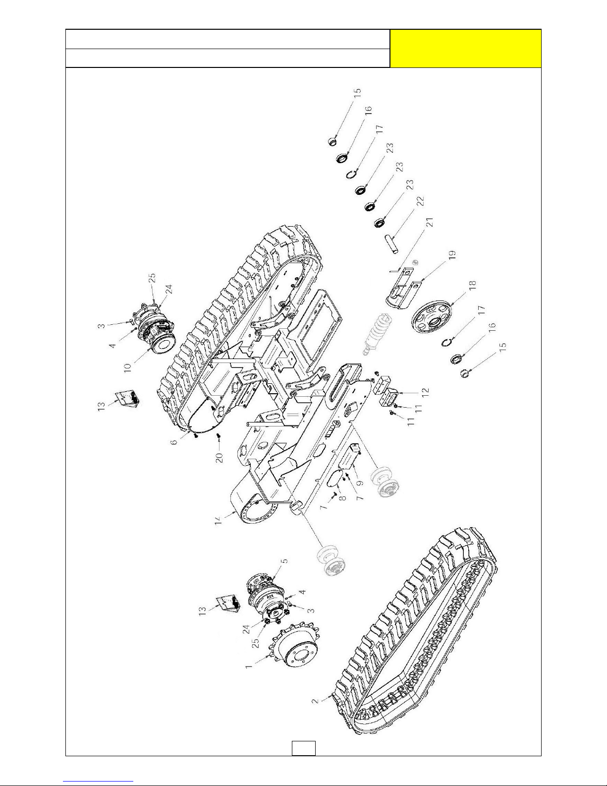
2
CHASSIS ASSEMBLY
ROBOCUT
McCONNEL
Page 56
3
REF. QTY. PART No. DESCRIPTION
CHASSIS ASSEMBLY
1 2 4000006 DRIVE SPRO CKET
2 2 4000263 R UBBER T RACK 250/72/ 47
3 20 4000352 CYLINDRIC HEAD SCREW
4 20 4000357 KNUR LED WASHER
5 1 4000360 R H T RACK DRIVE MO TO R
6 2 4001226 TR ACK MOTO R COVER
7 8 4000316 FLANGED HEAD SCREW
8 2 4000011 COVER PLAT E
9 2 4000775 TENSIONER COVER
10 1 4000359 LH TRACK DRIVE MO TO R
11 8 4000442 FLANGED HEAD SCREW
12 4 4000744 T R ACK BLOCKI N G
13 2 4000777 SEAL KIT
14 1 4000039 UNDERCARR IAGE HOU SING
15 4 4000010 BUSH
16 4 4000778 SEAL
17 4 4000024 CIRCLIP
18 2 4000005 SPROCKET
19 2 4000004 SPROCKET FO R K
20 8 4000353 FLANGED HEAD SCREW
21 4 4000032 RO LL PIN
22 2 4000009 PIN
23 6 4000776 BEARING
24 2 4001224 BOLT KIT (Pack of 5 Bol t s)
25 10 4001225 FLANG ED N U T
CHASSIS ASSEMBLY
ROBOCUT
McCONNEL
Page 57
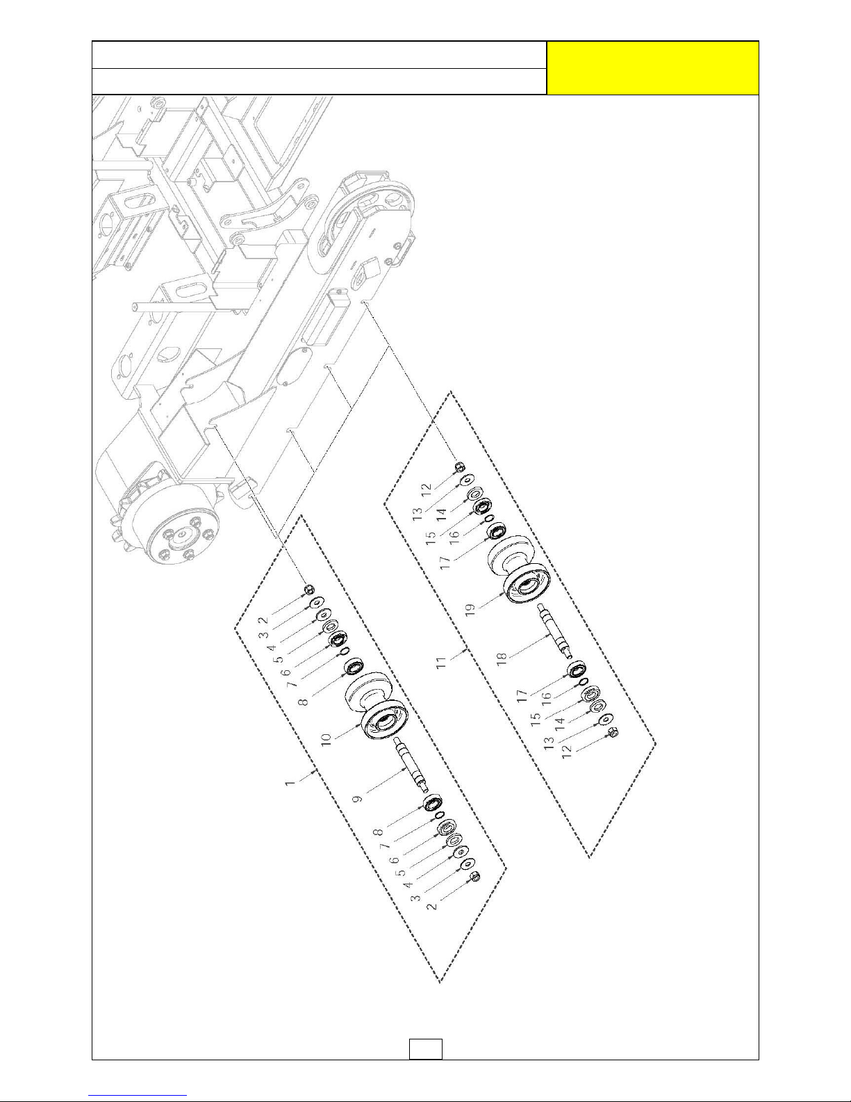
4
TRACK ROLLER ASSEMBLIES
ROBOCUT
McCONNEL
Page 58
5
TRACK ROLLER ASSEMBLIES
ROBOCUT
McCONNEL
REF. QTY. PART No. DESCRIPTION
TRACK ROLLER ASSEMBLIES
1 2 4000362 UPPER ROLLER ASSEMBLY - Comprising of:
2 2 4000355 LOCK NUT
3 2 4000019 WASHER
4 2 4000361 WASHER
5 2 4000351 ROLLER WASHER
6 2 4000780 ROLLER SEAL
7 2 4000023 CIRCLIP
8 2 4000781 TRACK ROLLER BEARING
9 1 4000015 ROLLER PIN
10 1 4000016 ROLLER
11 8 4000705 LOWER ROLLER ASSEMBLY - Compri sing of:
12 2 4000355 LOCK NUT
13 2 4000019 WASHER
14 2 4000351 ROLLER WASHER
15 2 4000780 ROLLER SEAL
16 2 4000023 CIRCLIP
17 2 4000781 TRACK ROLLER BEARING
18 1 4000015 ROLLER PIN
19 1 4000016 ROLLER
Page 59
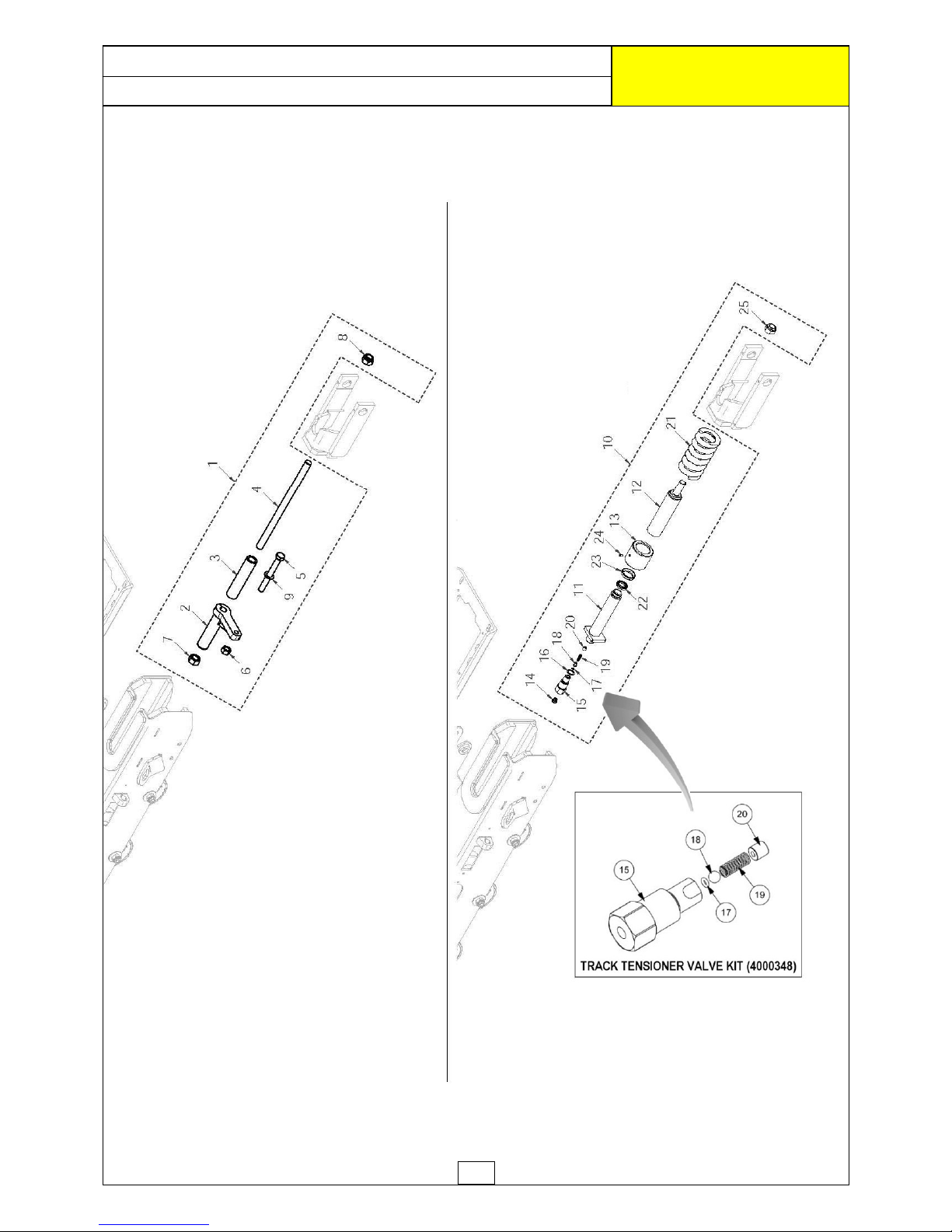
6
TRACK TENSIONER ASSEMBLIES
ROBOCUT
McCONNEL
Page 60
7
REF. QTY. PART No. DESCRIPTION
TRACK TENSIONER ASSEMBLIES
1 2 4000782 MECHAN ICAL TEN SIONER
- Comprising of:
2 1 4000783 TEN SIONER LEVER
3 1 4000784 SPAC ER
4 1 4000785 TENSIONER
5 1 4000786 HEX HEAD SCREW
6 1 4000787 NUT
7 1 4000788 NUT
8 1 4000018 LOCKNUT
9 1 4000253 WASHER
10 2 4001227 H YDRAULIC TEN SIONER
- Comprising of:
11 1 4000001 TENSIONER RO D
12 1 4000002 TENSIONER CYLI N DER
13 1 4000003 TENSIONER CAP
14 1 4000358 BUTTING H EAD FI TTING
1 4001301 BLANKING PLUG
(not shown)
15 1 4000012 * VALVE HO USING
16 1 8650318 BONDED SEAL
17 1 4000030 * O R ING
18 1 4000013 * VALVE
19 1 4000014 * SPRING
20 1 4000029 * PER FO R ATED NU T
21 1 4000008 SPRING
22 1 4000031 WASHER
23 1 4000028 BUSHING
24 1 4000354 GRU B SCREW
25 1 4000018 LOCKNUT
4000348 TRACK TENSIONER VALVE KIT c/o items
*
TRACK TENSIONER ASSEMBLIES
ROBOCUT
McCONNEL
Page 61
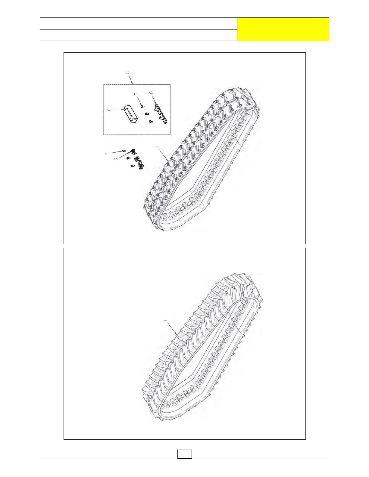
8
RUBBER TRACKS
ROBOCUT
McCONNEL
Page 62
9
RUBBER TRACKS
ROBOCUT
McCONNEL
EF. QTY. PART No. DESCRIPTION
RUBBER TRACKS
1 2 4000263 RUBBER TRACK 250/72/47
2 4000333 SUPER RUBBER TRACK 280/72/47
2 2 4000290 RUBBER TRACK (MOVEABLE STIRRUPS)
3 94 4000035 STEEL STIRRUP
4 282 4000037 BOLT
5 1 4000264 RIVETED STIRRUP KIT -
Comprising of:
6 46 4000036 RUBBER TRANSPORT BLOCK
7 138 4000038 BOLT
8 46 4000034 RIVETED STIRRUP
Page 63
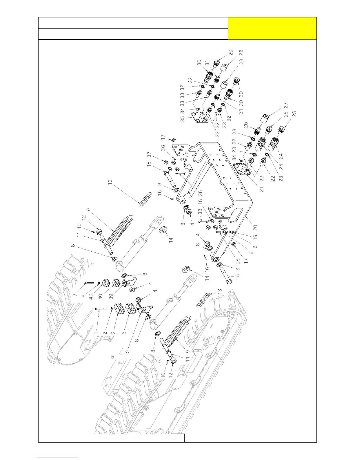
10
EQUIPMENT MOUNTING ASSEMBLY
ROBOCUT
McCONNEL
Page 64
11
EQUIPMENT MOUNTING ASSEMBLY
ROBOCUT
McCONNEL
REF. QTY. PART No. DESCRIPTION
EQUIPMENT MOUNTING ASSEMBLY
1 1 4000365 CYLINDRIC HEAD SCREW
2 1 4000078 WASHER
3 2 4000366 HOSE CLAMP
4 4 4000018 LOCK NUT
5 1 4000363 RH HOSE SUPPORT BRACKET
6 5 4000789 WASHER
7 1 4000108 CYLINDRIC HEAD SCREW
8 8 4000370 BAR WASHER
9 2 4000110 SPRING
10 2 4000369 SETSCREW
11 2 4000089 RAM PIN
12 2 4000090 RETAINING COLLAR
13 2 4000095 CHAIN
14 2 4000091 WASHER
15 2 4000373 SCREW
16 2 4000371 GREASE NIPPLE
17 2 4000790 WASHER
18 3 4000131 NUT
19 2 4000791 LOCKNUT
20 1 4000088 ATTACHMENT MOUNTING FRAME
21 1 4000093 RIGHT BULKHEAD FIXING PLATE
22 3 4000129 BULKHEAD FITTING
23 3 4000792 BONDED SEAL
24 2 4000133 QR COUPLING
25 2 4000139 PLUG (Option)
26 1 4000134 QR COUPLING
27 1 4000137 PLUG (Option)
28 2 4000668 PLUG (Option)
29 2 4000140 PLUG (Option)
30 2 4000132 QR COUPLING
31 2 4000135 QR COUPLING
32 4 7315818 BONDED SEAL
33 4 4000128 BULKHEAD FITTING
34 4 4000316 FLANGED HEAD SCREW
35 1 4000092 LEFT BULKHEAD FIXING PLATE
36 2 4000793 CYLINDRIC HEAD SCREW
37 4 4000130 NUT
38 2 4000794 SPLIT PIN
39 1 4000364 LH HOSE SUPPORT BRACKET
40 2 4000367 HOSE CLAMP
Page 65
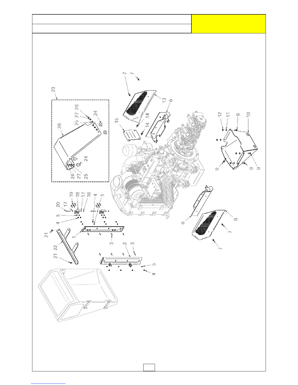
12
ENGINE COVERS ASSEMBLY
ROBOCUT
McCONNEL
Page 66
13
ENGINE COVERS ASSEMBLY
ROBOCUT
McCONNEL
REF. QTY. PART No. DESCRIPTION
ENGINE COVERS ASSEMBLY
1 1 4000169 RADIATOR LEFT SUPPORT
2 1 4000170 RADIATOR RIGHT SUPPORT
3 8 4000176 HEADLESS SCREW
4 12 4000075 AUTOGRIP NUT
5 12 9100103 WASHER
6 2 4000375 SIDE PROTECTION SUPPORT
7 4 4000379 FLANGED HEAD SCREW
8 1 4000164 RIGHT SIDE BONNET
9 5 4000380 FLANGED HEAD SCREW
10 1 4000172 REAR COVER
11 4 9100104 WASHER
12 4 4000381 AUTOGRIP NUT
13 1 4000165 LEFT SIDE BONNET
14 2 4000353 FLANGED HEAD SCREW
15 1 4000167 AIR FILTER BONNET SUPPORT
16 2 9163001 LOCK NUT
17 4 9100101 WASHER
18 2 4000383 HINGE
19 8 4000378 COUNTERSUNK HEAD SCREW
20 2 4000377 CYLINDRIC HEAD SCREW
21 2 4000316 FLANGED HEAD SCREW
22 1 4000171 RADIATOR CLOSING SUPPORT
23 1 4000795 AIR FILTER BONNET KIT - comprising of:
24 4 4000609 ANTI-VIBRATION BLOCK
25 4 9100104 WASHER
26 4 4000376 SCREW
27 4 9100204 SPRING WASHER
28 1 4000166 AIR FILTER BONNET
Page 67
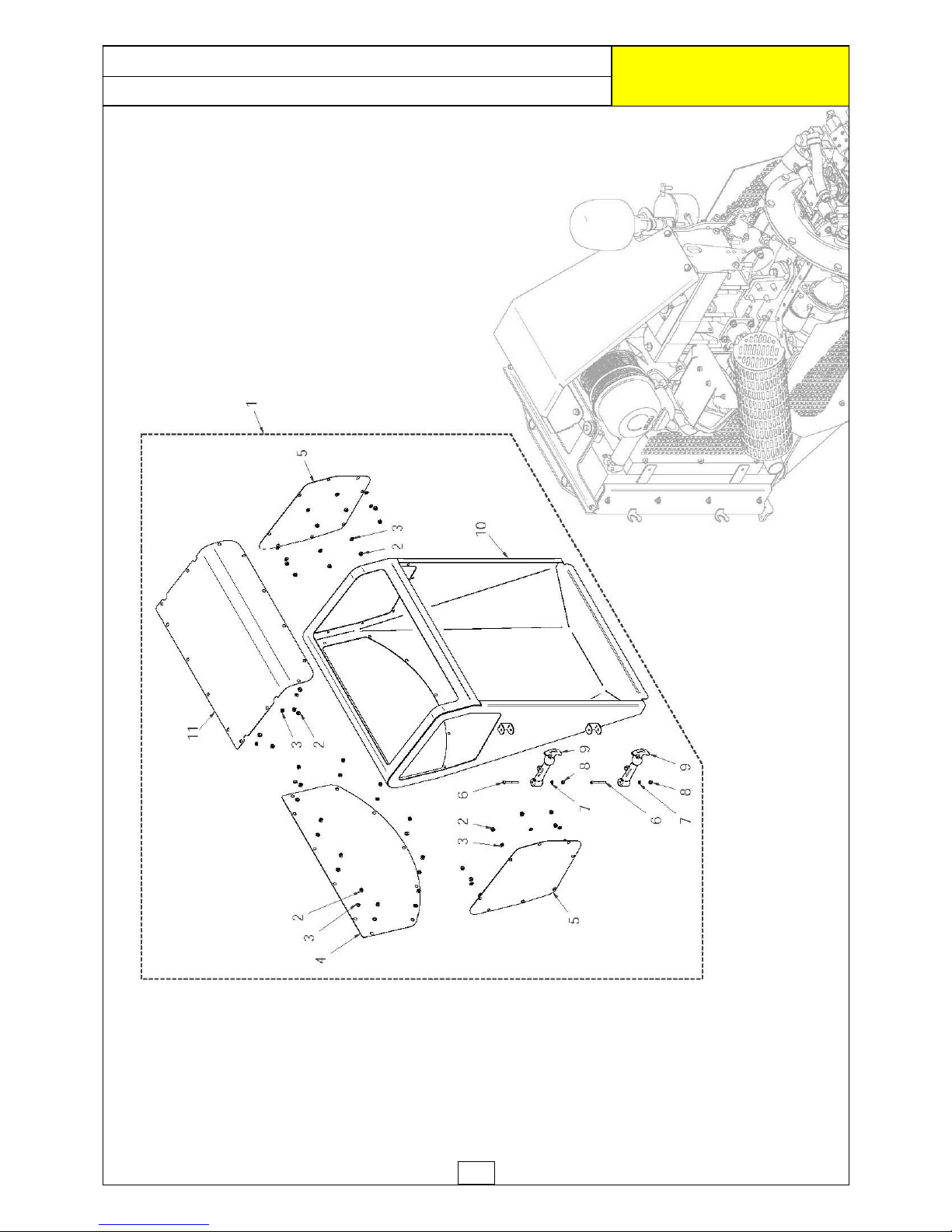
14
RADIATOR COVERS ASSEMBLY
ROBOCUT
McCONNEL
Page 68
15
REF. QTY. PART No. DESCRIPTION
RADIATOR COVERS ASSEMBLY
1 1 4000401 RADIATOR BONNET ASSEMBLY
- comprising of:
2 41 4001229 LOCKNUT
3 41 9100102 WASHER
4 1 4000155 CENTRAL LOWER MESH
5 2 4000154 SIDE MESH
6 2 4000107 CYLINDRIC HEAD SCREW
7 2 4000798 WASHER
8 2 4000799 LOCKNUT
9 2 4000112 BONNET FASTENER
10 1 4001230 RADIATOR BONNET
11 1 4000374 CENTRAL UPPER MESH
12 1 4001368 RUBBER SEAL
(n o t illus trate d )
RADIATOR COVERS ASSEMBLY
ROBOCUT
McCONNEL
Page 69
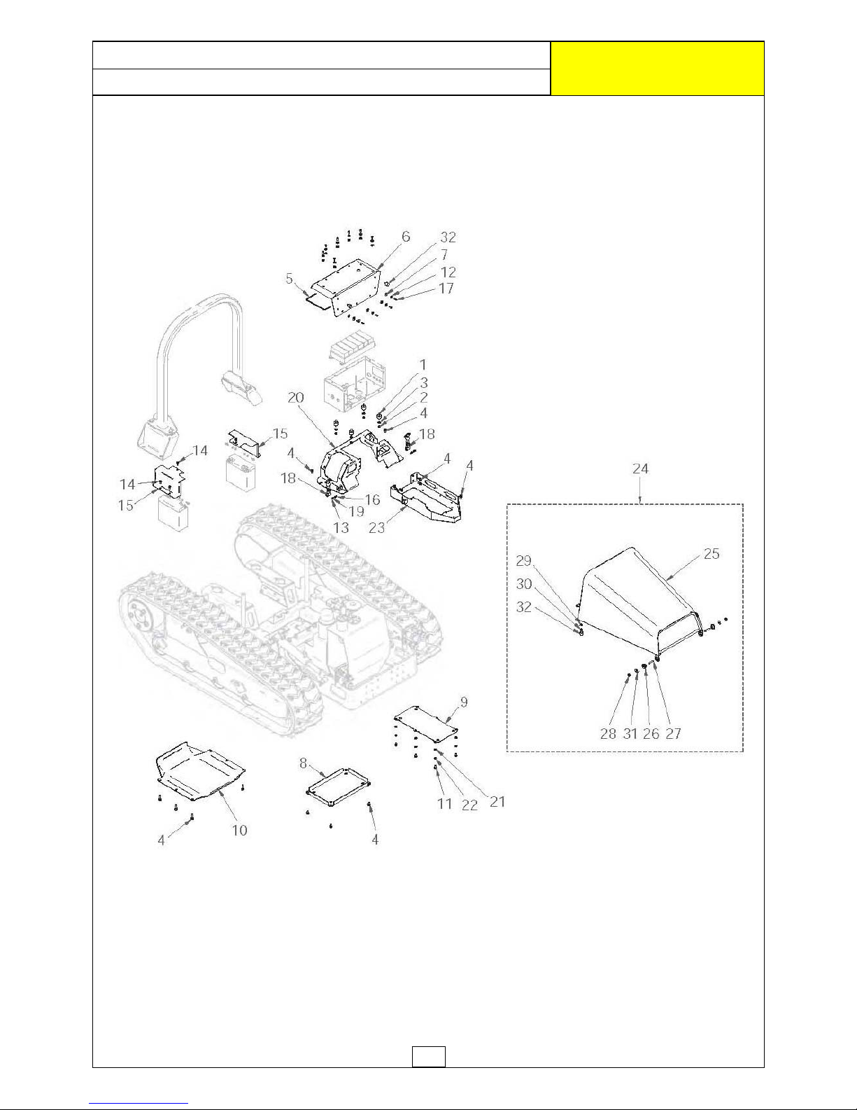
16
MACHINE COVERS ASSEMBLY
ROBOCUT
McCONNEL
Page 70
17
MACHINE COVERS ASSEMBLY
ROBOCUT
McCONNEL
REF. QTY. PART No. DESCRIPTION
MACHINE COVERS ASSEMBLY
1 4 4000386
A
NT I-VIBRAT ION BLOCK
2 4 9163003 LOCK NUT
3 4 4000321 WASHER (LARGE SERIES)
4 17 4000353 FLANGED HEAD SCREW
5 1 4000800 RUBBER GASKET
6 1 4000801 ELECTRICAL BOX COVER
7 12 4000388 RUBBER WASHER
8 1 4000161 VALVE COVER PLAT E
9 1 4000162 TANK COVER PLATE
10 1 4000168 OIL SUMP PROTECTION
11 6 4000376 SCREW
12 16 4000321 WASHER
13 2 4000107 CYLINDRIC HEAD SCREW
14 6 4000316 FLANGED HEAD SCREW
15 2 4000153 BATTERY COVER
16 2 9163001 LOCKNUT
17 12 4000387 HEX SKT BUTTON HEAD SCREW
18 2 4000112 BONNET FASTENER
19 4 9100101 WASHER
20 1 4000098 ELECTRIC BOX MOUNTING FRAME
21 6 9100104 WASHER
22 6 9100204 SPRING WASHER
23 1 4000099 REMOTE RECEIVER MOUNTING
24 1 4000803 UPPER BONNET ASSEMBLY
- comprising of:
25 1 4000804 UPPER BONNET
26 2 4000163 BUSHING
27 2 4000384 HEADLESS SCREW
28 2 4000381
A
UTOGRIP NUT
29 2 4000075
A
UTOGRIP NUT
30 2 9100103 WASHER
31 2 4000385 WASHER
32 4 4000251
A
NT I-VIBRAT ION BLOCK
Page 71
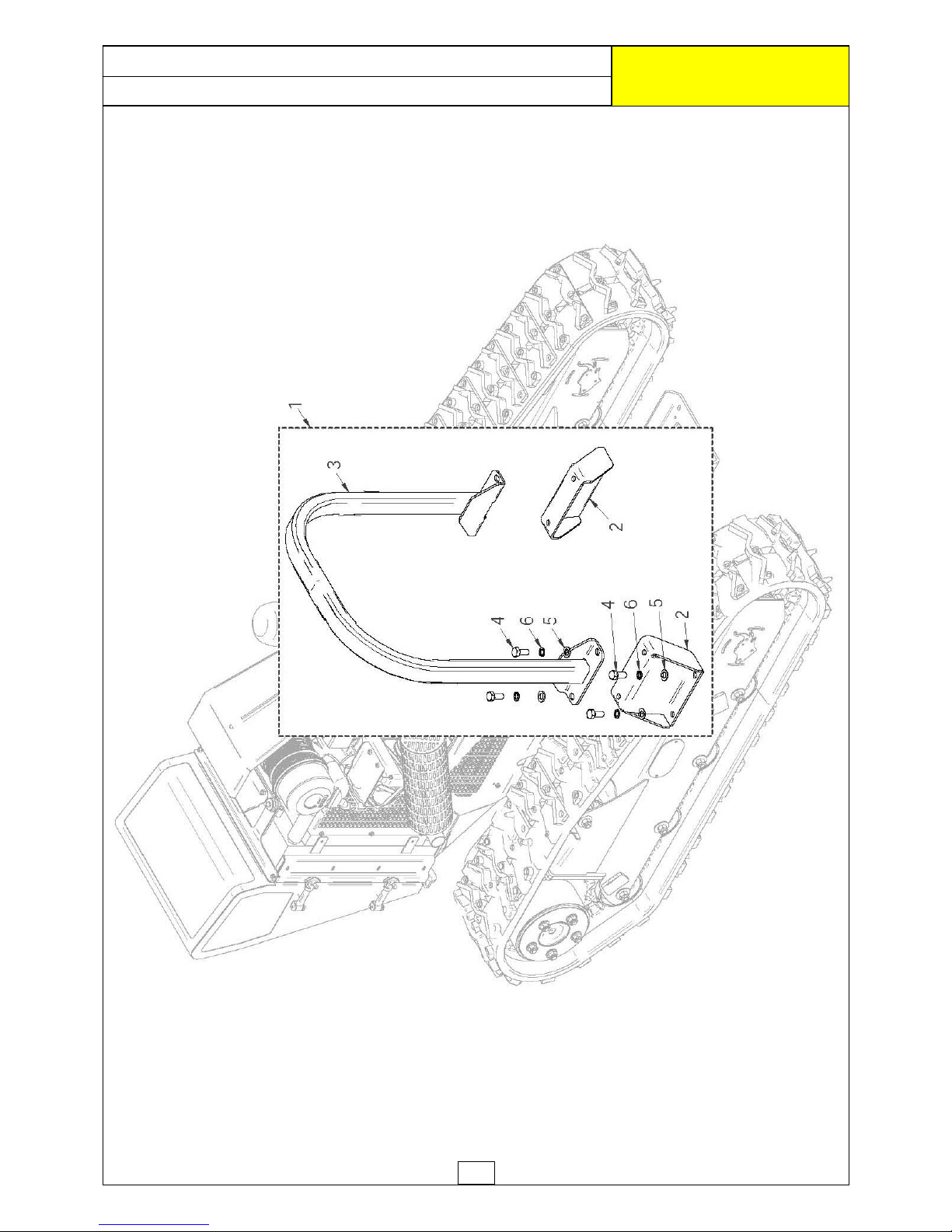
18
ROLL BAR ASSEMBLY
ROBOCUT
McCONNEL
Page 72
19
ROLL BAR ASSEMBLY
ROBOCUT
McCONNEL
REF. QTY. PART No. DESCRIPTION
ROLL BAR ASSEMBLY
1 1 4000805 ROLL BAR KIT
- comprising of:
2 2 4000151 ROLL BAR SUPPORT
3 1 4000152 ROLL BAR
4 8 4000175 HEX HEAD SCREW
5 8 9100207 SPRING WASHER
6 8 0100106 WASHER
Page 73
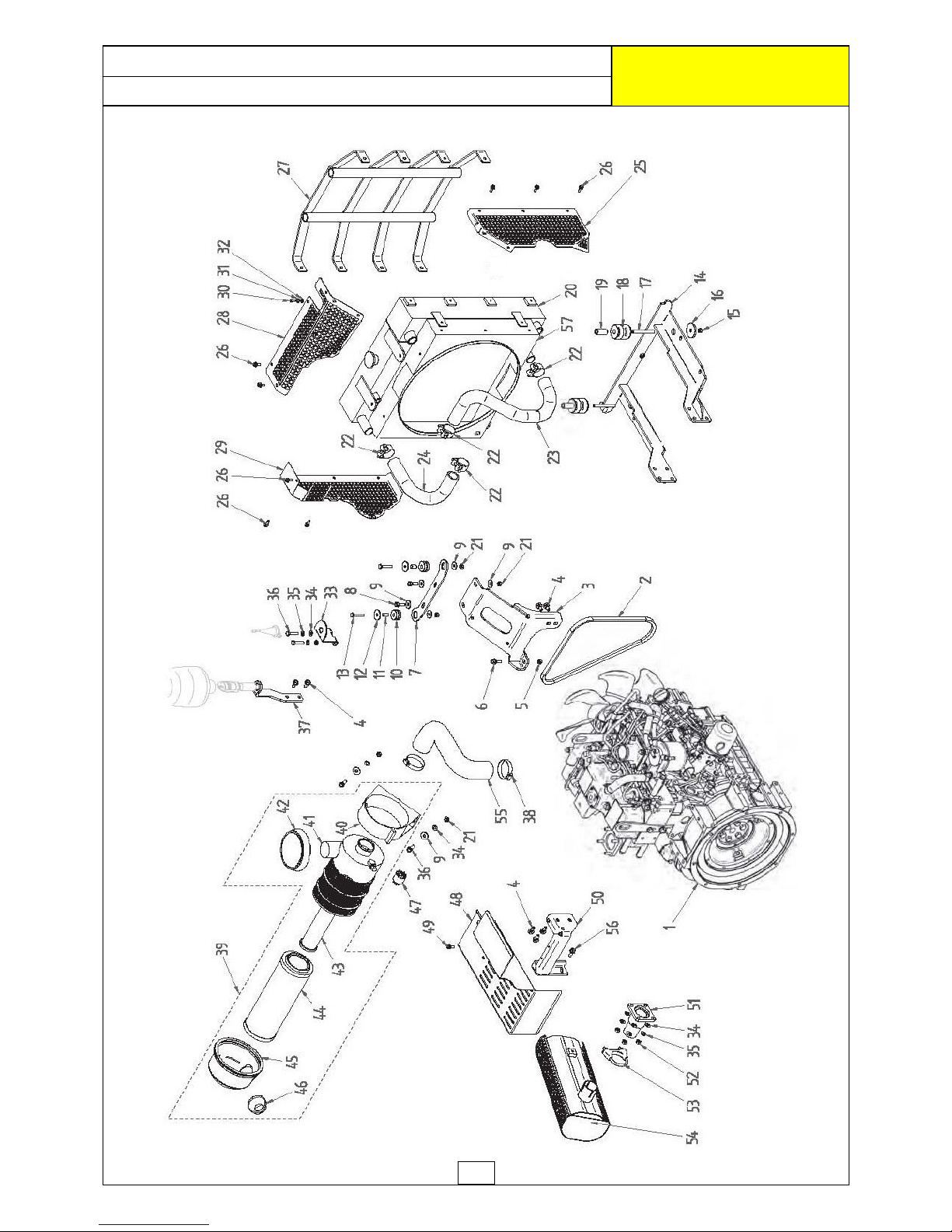
20
DIESEL ENGINE
ROBOCUT
McCONNEL
Page 74
21
REF. QTY. PART No. DESCRIPTION
DIESEL ENGINE
1 1 4000701 ISUZU ENGINE (40HP)
2 1 4000275 MOTOR BELT
3 1 4000054 AIR FILTER MOUNTING
4 7 4000353 FLANGED HEAD SCREW
5 8 4000381 AUTOGRIP NUT
6 1 4000380 FLANGED HEAD SCREW
7 1 4001231 RADIATOR BRACKET
8 2 4000806 HEXAGON HEAD SCREW
9 8 4000385 WASHER (LARGE SERIES)
10 2 4000084 ANTI-VIBRATION RUBBER
11 2 4000389 SPACER
12 2 4000080 WASHER (LARGE SERIES)
13 2 4000807 HEXAGON HEAD SCREW
14 1 4001232 RADIATOR SUPPORT BRACKET
15 2 4000416 AUTOGRIP NUT
16 2 4000390 WASHER
17 2 4000068 HEADLESS SCREW
18 2 4000083 ANTI-VIBRATION MOUNTING
19 2 4000391 SPACER
20 1 4001415 RADIATOR*
1 4000046 RADIATOR* c/w COWL
(for Pneumatic Fans only)
21 6 4000808 LOCKNUT
22 4 4000607 HEAVY DUTY HOSE CLIP
23 1 4000392 RADIATOR HOSE LEFT
24 1 4000393 RADIATOR HOSE RIGHT
25 1 4000041 LEFT MESH GUARD
26 11 4000394 FLANGED HEAD SCREW
27 1 4000047 RADIATOR PROTECTION
28 1 4000043 UPPER MESH GUARD
29 1 4000042 RIGHT MESH GUARD
30 1 4000395 SCREW
31 1 9100203 WASHER
32 1 9100103 WASHER
33 1 4000396 ANTENNA BRACKET
34 8 9100104 WASHER
35 6 9100204 SPRING WASHER
36 4 9313074 SETSCREW
37 1 4000286 LIGHT BRACKET
38 2 4000397 CLIP
39 1 4000400 AIR FILTER COMPLETE c/w CLIP
40 1 4000052 AIR FILTER BRACKET
41 1 4000048 AIR FILTER HOUSING
42 1 4000051 AIR FILTER COVER
Continued .. .
DIESEL ENGINE
ROBOCUT
McCONNEL
Page 75
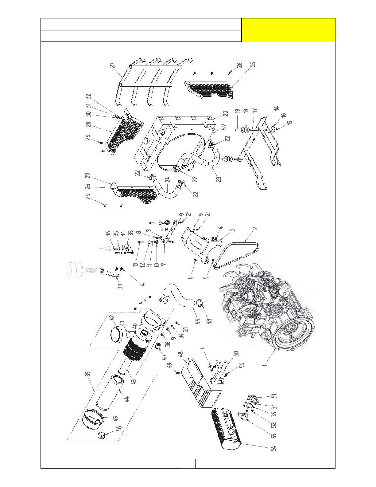
22
DIESEL ENGINE
ROBOCUT
McCONNEL
Page 76
23
REF. QTY. PART No. DESCRIPTION
DIESEL ENGINE (Continued)
43 1 4000261 SECONDARY AIR FILTER
44 1 4000260 PRIMARY AIR FILTER
45 1 4000280 FILTER HOUSING CAP
46 1 4000279 RUBBER VALVE
47 1 4000281 CLOGGING SENSOR
48 1 4001233 ALTERNATOR LID
49 2 4000810 FLANGED HEAD SCREW
50 1 4000062 EXHAUST SUPPORT
51 1 4000061 EXHAUST MANIFOLD
52 4 9113004 NUT
53 1 4000399 CLIP
54 1 4001234 EXHAUST SILENCER
55 1 4000398 RUBBER HOSE
56 1 4000319 FLANGED HEAD SCREW
57 1 4001416 FAN COWL
(ROBO031400418 ►ROBO031600824)
1 4001417 FAN COWL
(ROBO031600825 ►)
DIESEL ENGINE
ROBOCUT
McCONNEL
Page 77
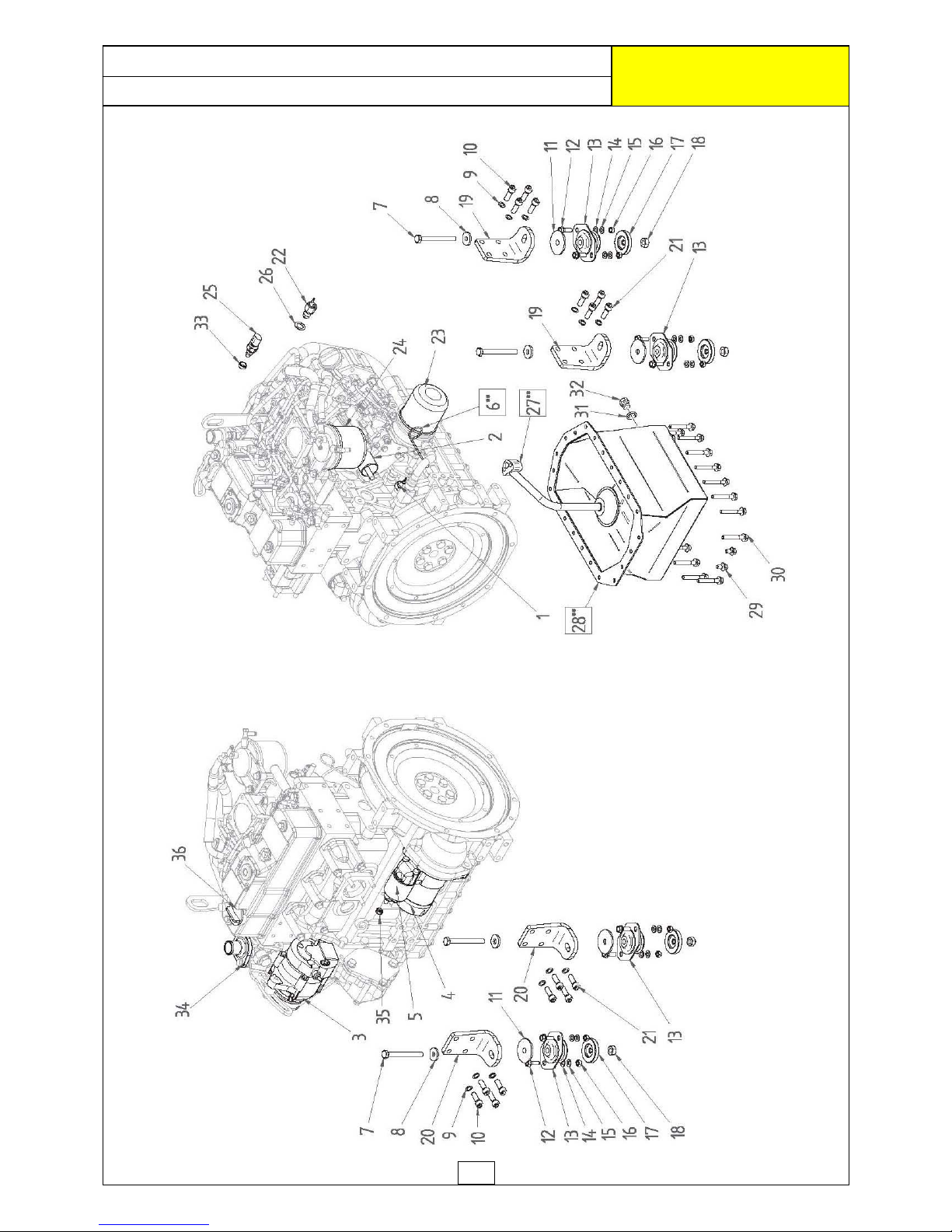
24
DIESEL ENGINE COMPONENTS
ROBOCUT
McCONNEL
Page 78
25
REF. QTY. PART No. DESCRIPTION
DIESEL ENGINE COMPONENTS
1 1 4000403 OIL SENSOR
2 1 4000404 SOLENOID - ELECTRICAL STOP
3 1 4000405 ALTERNATOR
4 1 4000406 STARTER MOTOR
5 1 4000407 SOLENOID - STARTER MOTOR
6 1 4000408 DIPSTICK
7 4 4000409 SETSCREW
8 4 9100106 WASHER
9 16 4000761 KNURLED WASHER
10 8 4000411 CYLINDRIC HEAD SCREW
11 4 4000412 SILENCING WASHER
12 8 4001235 HEX SKT BUTTON HEAD SCREW
13 4 4001336 REAR ANTI-VIBRATION MOUNTING
14 8 9100105 WASHER
15 8 4000415 WASHER
16 8 4000416 AUTOGRIP NUT
17 4 4000417 ANTI-VIBRATION BLOCK
18 4 4000418 AUTOGRIP NUT
19 2 4000419 LH ENGINE MOUNTING
20 2 4000420 RH ENGINE MOUNTING
21 8 4000421 CYLINDRIC HEAD SCREW
22 1 4001420 THERMOSTAT
23 1 4000257 ENGINE OIL FILTER
24 1 4000105 FUEL FILTER
25 1 4000698 WATER SENSOR
26 1 4000424 COPPER WASHER
27 1 4000425 SUCTION STRAINER
28 1 4000053 OIL SUMP
29 4 4000353 FLANGED HEAD SCREW
30 20 4000812 FLANGED HEAD SCREW
31 1 4000427 COPPER WASHER
32 1 4000428 PLUG
33 1 4001421 SPACER
34 1 4000814 WATER PUMP
35 1 4000815 FLANGED NUT
36 1 4000735 OIL FILLER PLUG
DIESEL ENGINE COMPONENTS
ROBOCUT
McCONNEL
Page 79
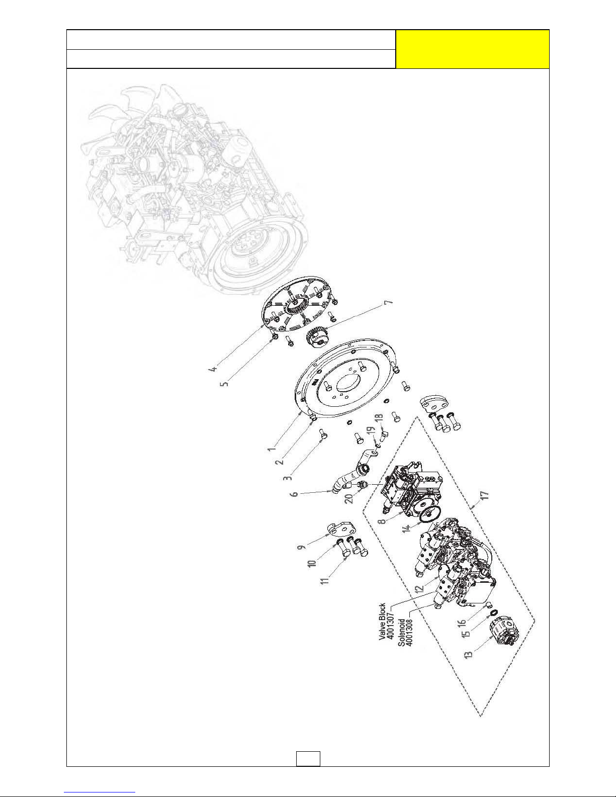
26
PUMPS ASSEMBLY (Builds S/No: ►ROBO071100027 )
ROBOCUT
McCONNEL
Page 80
27
PUMPS ASSEMBLY (Builds S/No: ►ROBO071100027 )
ROBOCUT
McCONNEL
REF. QTY. PART No. DESCRIPTION
PUMPS ASSEMBLY (Early Builds)
Machines S/N: ►ROBO071100027
1 1 4000429 FLYWHEEL PUMP ADAPTOR
2 9 4000410 KNURLED WASHER
3 8 4000209 HEX HEAD SCREW
4 1 4000297 FLYWHEEL
5 8 4000430 FLANGED HEAD SCREW
6 1 4000431 PUMP MANIFOLD
7 1 4000432 GROOVED JOINT
8 1 4000296 ROTOR PUMP
9 2 4000433 PUMP CLAMP
10 6 4000434 LOCK WASHER
11 6 4000435 HEX HEAD SCREW
12 1 4001312 TANDEM PISTON PUMP
13 1 4001313 GEAR PUMP
14 1 4000438 O RING
15 1 4001314 O RING
16 1 4001315 DRIVE COUPLING
17 1 4001316 PUMPS ASSEMBLY
18 1 4000440 SETCREW
19 1 4000758 WASHER
20 1 7315797 CONNECTOR
Page 81
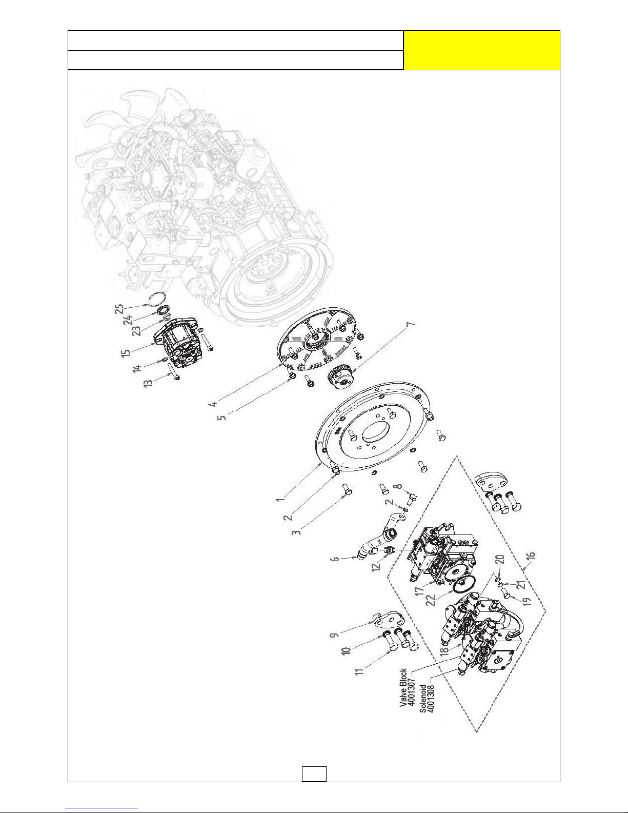
28
PUMPS ASSEMBLY (Current Builds)
ROBOCUT
McCONNEL
Page 82
29
PUMPS ASSEMBLY (Current Builds)
ROBOCUT
McCONNEL
REF. QTY. PART No. DESCRIPTION
PUMPS ASSEMBLY (Current Builds)
Machines S/N: ROBO071100028 ►
1 1 4000429 FLYWHEEL PUMP ADAPTOR
2 9 4000410 KNURLED WASHER
3 8 4000209 HEX HEAD SCREW
4 1 4000297 FLYWHEEL
5 8 4000430 FLANGED HEAD SCREW
6 1 4000431 PUMP MANIFOLD
7 1 4000432 GROOVED JOINT
8 1 4000440 HEX HEAD SCREW
9 2 4000433 PUMP CLAMP
10 6 4000434 LOCK WASHER
11 6 4000435 HEX HEAD SCREW
12 1 7315797 CONNECTOR
13 2 4000437 CYLINDRIC HEAD SCREW
14 2 4000758 WASHER
15 1 4000345 GEAR PUMP
16 1 4000439 PISTON PUMP
17 1 4000296 ROTOR PUMP
18 1 4000436 TANDEM PISTON PUMP
19 2 4000210 HEX HEAD SCREW
20 2 4000410 KNURLED WASHER
21 2 9100105 WASHER
22 1 4000438 O RING
23 1 4000346 OIL SEAL
24 1 4000898 PUMP RING
25 1 4001236 CIRCLIP
Page 83
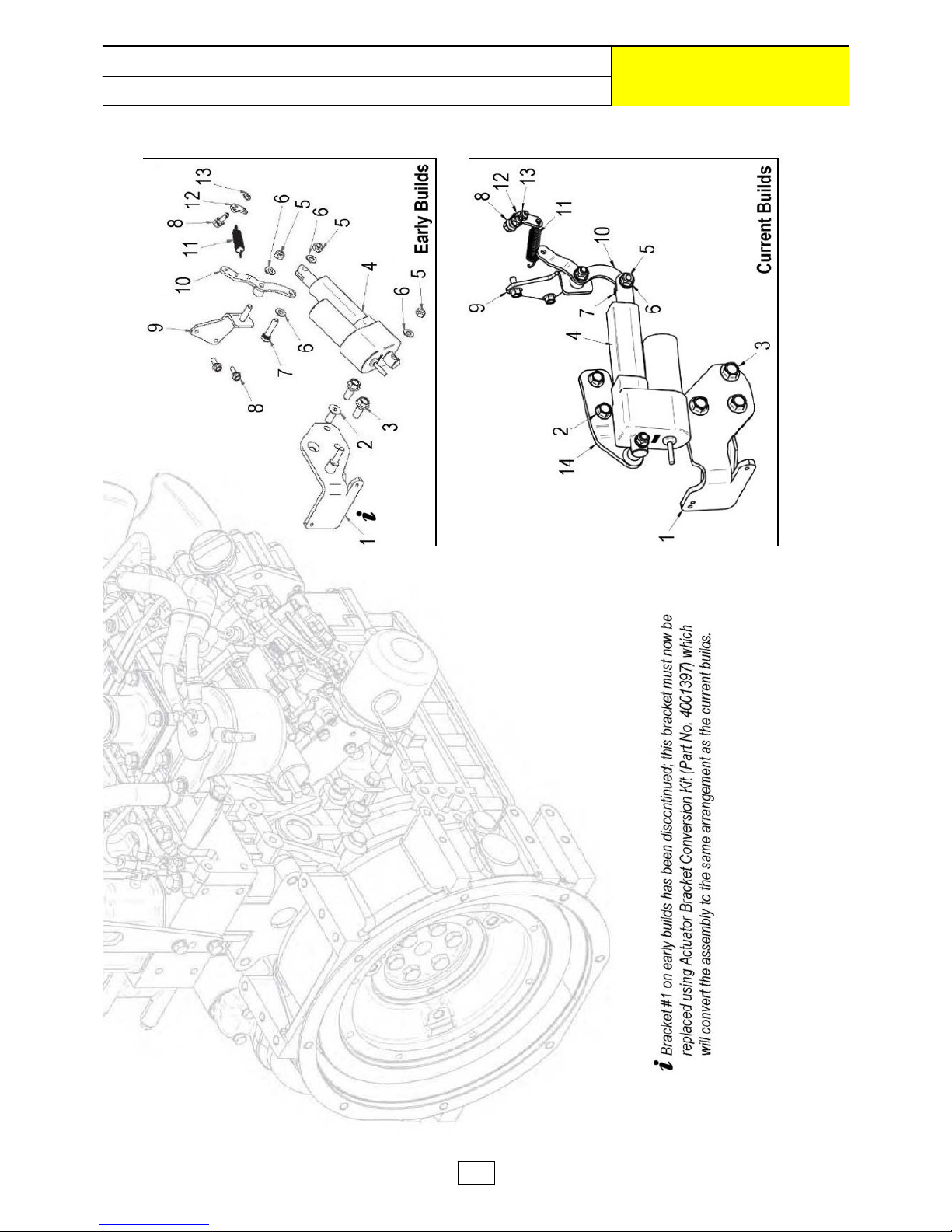
30
ACTUATOR ASSEMBLY
ROBOCUT
McCONNEL
Page 84
31
REF. QTY. PART No. DESCRIPTION
ACTUATOR ASSEMBLY (Early Builds)
1 1 4000057 BRACKET
(
Item discontinued
)
2 1 4000441 COUNTERSUNK HEAD SCREW
3 2 4000442 FLANGED HEAD SCREW
4 1 4000086 ACTUATOR
5 3 4000381 AUTOGRIP NUT
6 4 4000078 WASHER
7 1 4000806 HEX HEAD SCREW
8 4 4000316 FLANGED HEAD SCREW
9 1 4000058 THROTTLE BRACKET
10 1 4000059 ACTUATOR ARM
11 1 4000074 THROTTLE SPRING
12 1 4000060 ACTUATOR SPRING LINKAGE
13 2 4000443 AUTOGRIP NUT
Bracket Part No. 4000057 has been discontinued; replacement of this bracket
now requires the use of Actuator Bracket Conversion Kit (Part No. 4001397)
-
this kit converts the assembly to the same arrangement as current builds.
REF. QTY. PART No. DESCRIPTION
ACTUATOR ASSEMBLY (Current Builds)
1 1 4001408 BRACKET
2 2 4000441 COUNTERSUNK HEAD SCREW
3 2 4000442 FLANGED HEAD SCREW
4 1 4000086 ACTUATOR
5 3 4000380 AUTOGRIP NUT
6 4 4000078 WASHER
7 1 4000806 HEX HEAD SCREW
8 4 4000316 FLANGED HEAD SCREW
9 1 4000058 THROTTLE BRACKET
10 1 4001407 ACTUATOR ARM
11 1 4000074 THROTTLE SPRING
12 1 4000060 ACTUATOR SPRING LINKAGE
13 2 4000443 AUTOGRIP NUT
14 1 4001406 BRACKET
A
CTUATOR ASSEMBLY
ROBOCUT
McCONNEL
Page 85
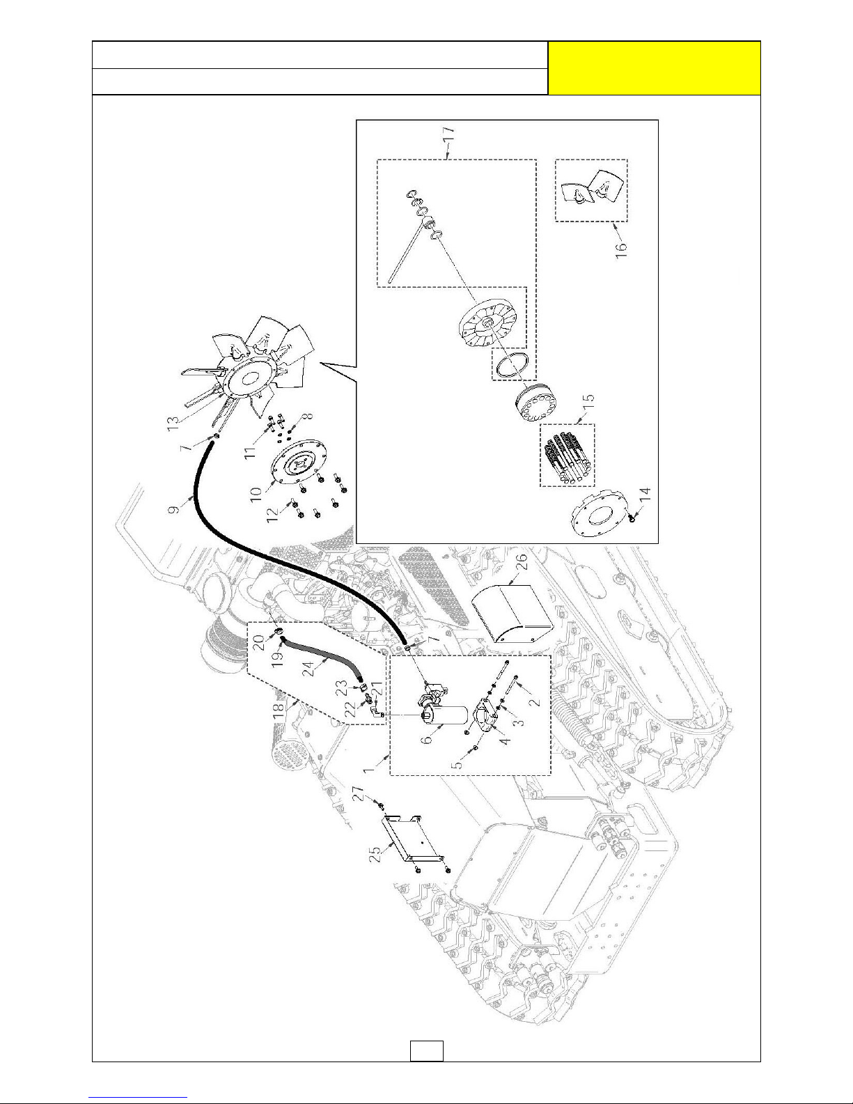
32
FAN ASSEMBLY (S/No. ►ROBO031400418)
ROBOCUT
McCONNEL
Page 86
33
REF. QTY. PART No. DESCRIPTION
REVERSIBLE FAN ASSEMBLY
1 1 4001237 COMPRESSOR ASSEMBLY
- comprising of:
2 2 4001238 CYLINDRIC HEAD SCREW
3 2 4000789 WASHER
4 1 4000450 COMPRESSOR CLAMP
5 2 4000449 FLANGED NUT
6 1 4000446 COMPRESSOR
7 2 4000453 HOSE CLAMP
8 4 4001239 KNURLED WASHER
9 1 4000466 AIR HOSE
10 1 4001240 FAN FLANGE
11 4 4000543 CYLINDRIC HEAD SCREW
12 8 4000472 FLANGED HEAD SCREW
13 1 4001241 REVERSIBLE FAN
14 8 4001242 SCREW
15 12 4001243 SPRING KIT
16 4 4000699 BLADE SET FOR FAN (2 BLADES)
17 1 4001244 IRON PIPE KIT
18 1 4001245 AIR FILTER SUCTION LINE KIT
- comprising of:
19 1 4001246 SLEEVING
20 1 4001247 JUBILEE CLIP
21 1 4001248 CONNECTOR
22 1 4001249 HOSE CONNECTOR
23 1 4000467 HOSE CLAMP
24 1 4001250 HOSE
25 1 4001251 COMPRESSOR REAR COVER
26 1 4001252 COMPRESSOR FRONT COVER
27 1 4000316 FLANGED HEAD SCREW
FAN ASSEMBLY (S/No. ►ROBO031400418)
ROBOCUT
McCONNEL
Page 87
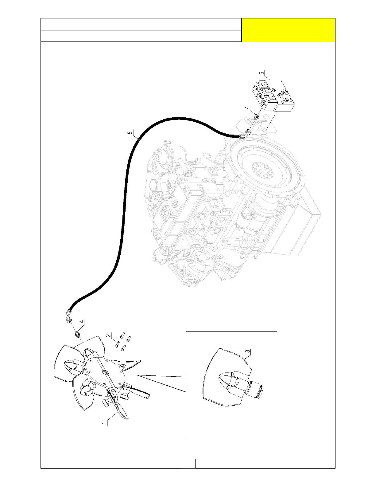
34
FAN ASSEMBLY (S/No. ROBO031400419 ►ROBO031600824)
ROBOCUT
McCONNEL
Page 88
35
REF. QTY . PART No . DESCRIPTION
REVERSI BLE FAN ASSE M BLY
Machines S/No: ROBO031400418 ►ROBO031600824
1 1 4001 09 8 REVER SIBLE FAN
2 4 4000543 CYLINDRIC HEAD SCREW
3 6 4001099 FAN BLADE
4 1 4001100 ADAPTOR
5 1 4003186 H YDRAULIC HO SE
6 1 4001546 VALVE BLOCK
3 4001656 CARTRIDGE
3 4001657 COIL
1 4001658 SEAL KI T
FAN ASSEMBLY (S/No. ROBO031400419 ►ROBO031600824)
ROBOCUT
McCONNEL
Page 89
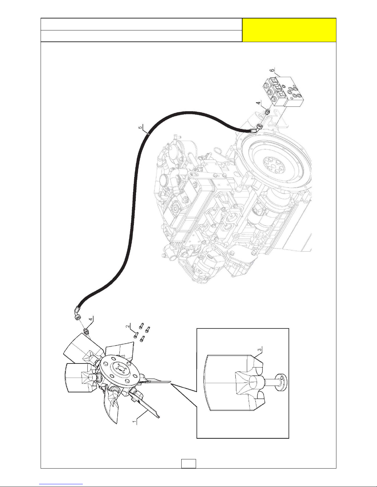
36
FAN ASSEMBLY (S/No. ROBO031600825 ►)
ROBOCUT
McCONNEL
Page 90
37
REF. QTY . PART No . DESCRIPTION
REVERSI BLE FAN ASSE M BLY
Machines S/No: ROBO031600825 ►
1 1 4001 41 4 REVER SIBLE FAN
2 4 4000543 CYLINDRIC HEAD SCREW
3 3 40 01 41 8 FAN BL ADE KIT (SET OF 2 BLADES)
4 1 4001100 ADAPTOR
5 1 4003186 H YDRAULIC HO SE
6 1 4001546 VALVE BLOCK
3 4001656 CARTRIDGE
3 4001657 COIL
1 4001658 SEAL KI T
FAN ASSEMBLY (S/No. ROBO031600825 ►)
ROBOCUT
McCONNEL
Page 91
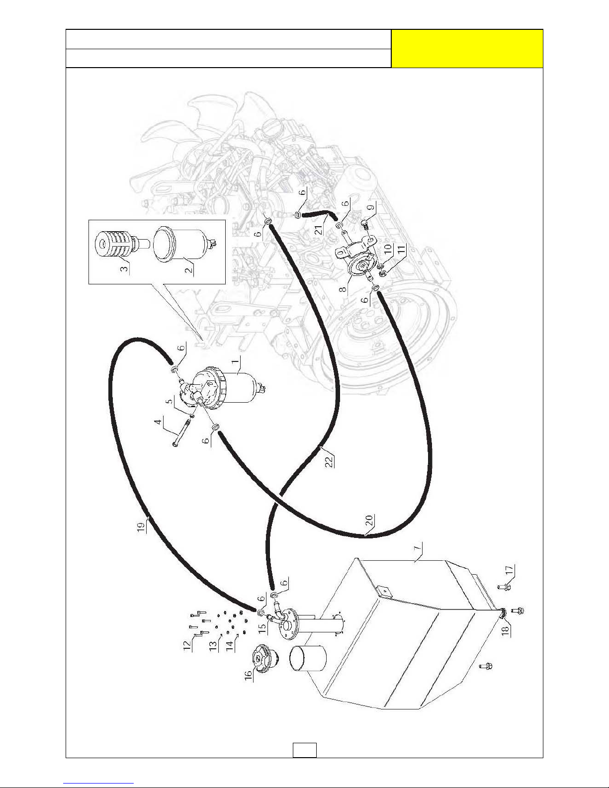
38
DIESEL FUEL CIRCUIT
ROBOCUT
McCONNEL
Page 92
39
DIESEL FUEL CIRCUIT
ROBOCUT
McCONNEL
REF. QTY. PART No. DESCRIPTION
DIESEL FUEL CIRCUIT
1 1 4000292 PRIMARY FUEL FILTER
2 1 4000341 FUEL FILTER CAP
3 1 4000342 PRIMARY FILTER CARTRIDGE
4 1 9213144 HEX HEAD SCREW
5 1 9100104 WASHER
6 8 4000467 HOSE CLAMP
7 1 4000096 FUEL TANK
8 1 4000126 FUEL PUMP
9 2 4000472 FLANGED HEAD SCREW
10 2 9100103 WASHER
11 2 4000443 AUTOGRIP NUT
12 6 4000106 CYLINDRIC HEAD SCREW
13 6 4000113 SPRING WASHER
14 6 9100101 WASHER
15 1 4000473 FUEL LEVEL SENSOR
16 1 4000474 FUEL CAP
17 8 7315750 FLANGED HEAD SCREW
18 2 4000127 PLUG
19 1 4000468 DIESEL HOSE - 1190mm
20 1 4000469 DIESEL HOSE - 870mm
21 1 4000470 DIESEL HOSE - 260mm
22 1 4000471 DIESEL HOSE - 1350mm
Page 93
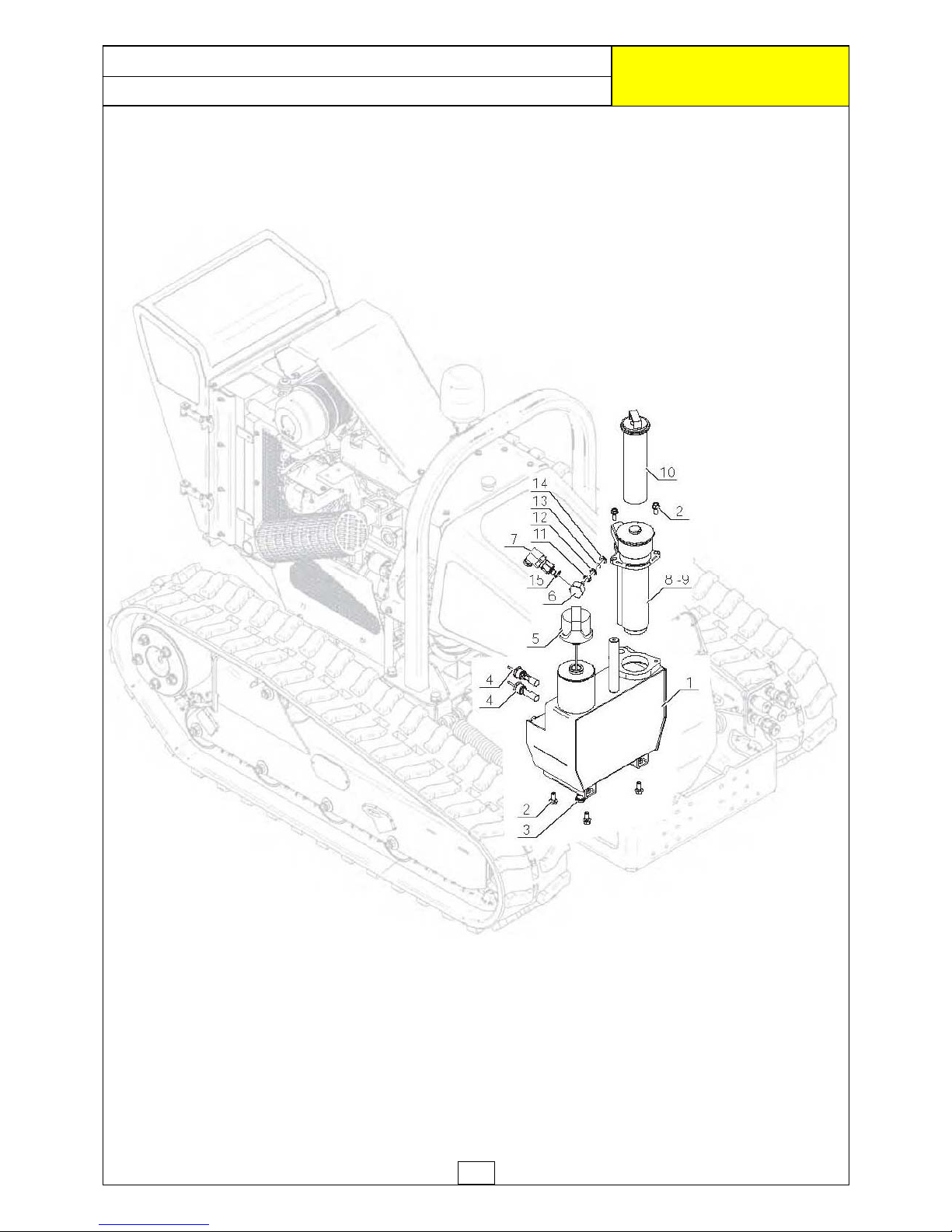
40
OIL TANK ASSEMBLY
ROBOCUT
McCONNEL
Page 94
41
OIL TANK ASSEMBLY
ROBOCUT
McCONNEL
REF. QTY. PART No. DESCRIPTION
OIL TANK ASSEMBLY
1 1 4000097 OIL TANK
2 6 7315750 FLANGED HEAD SCREW
3 2 4000127 PLUG
4 2 4000148 LEVEL SENSOR
5 1 4000124 OIL CAP / LEVEL
6 1 4000475 OIL FILTER SENSOR BRACKET
7 1 4000476 FILTER CLOGGING SWITCH
8 1 4000122 OIL FILTER HOUSING
9 1 4000817 OIL FILTER
10 1 4000259 OIL FILTER ELEMENT
11 1 4000818 NUT
12 1 4000819 O RING WASHER
13 1 4000820 O RING
14 1 4000821 O RING STOPPER
15 1 4000822 BOLT SEAL
Page 95
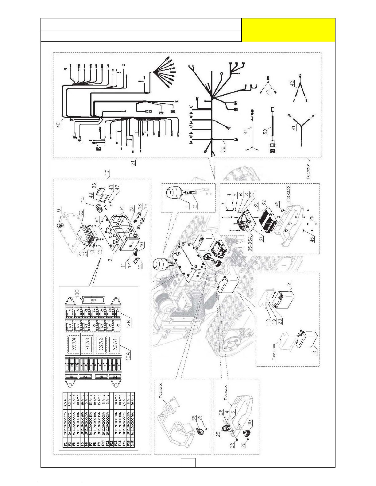
42
ELECTRICAL COMPONENTS
ROBOCUT
McCONNEL
Page 96
43
ELECTRICAL COMPONENTS
ROBOCUT
McCONNEL
REF. QTY. PART No. DESCRIPTION
ELECTRICAL COMPONENTS
1 1 4000283 ROTATING LIGHT (BEACON)
2 1 4000284 LIGHT CONNECTION
3 4 4000823 WASHER
4 5 4000544 WASHER
5 5 4000789 WASHER
6 4 4000824 SCREW
7 4 4000452 SCREW
8 2 4000181 BATTERY
9 1 4000306 RED EMERGENCY SWITCH
10 1 4000307 PLUG
11 1 4000308 CONNECTOR
12 2 4000309 SCREW
13 1 4000825 RELAYS FUSE BOX
13a 4 4000302 RELAY WITH DIODE
13b 21 4000303 MICRO RELAY
13c 1 4000311 FUSE
14 1 4000145 IGNITION SWITCH
15 1 4000313 PRE AIR HEATER
16 1 4000326 INJECTION PUMP DELAY
17 1 4000802 ELECTRICAL BOX
18 4 4000316 SCREW
19 4 4000789 WASHER
20 4 4000075 NUT
21 1 4000826 WIRING LOOMS - ELECTRICAL SYSTEM
22 1 4000318 CONNECTOR PLUG
23 1 4000798 WASHER
24 1 4000799 LOCK NUT
25 1 4000301 HORN
26 3 4000316 SCREW
27 4 4000827 WASHER
28 8 4000791 LOCK NUT
29 8 4000321 WASHER
30 1 4000322 SHUNT BOX
31 1 4000828 SOUNDPROOF PROTECTION
32 1 4000829 CONTROL UNIT
33 1 4000830 INDICATOR
34 1 4000831 BOX PROTECTION
35 1 4000729 RECEIVER UNIT (870 MHZ)
35A 1 4000730 RECEIVER UNIT (915 MHZ)
36 1 4000833 WIRING LOOM - CONTROL UNIT
37 1 4000834 SUPPORT RECEIVER
38 1 4000835 CLIP
39 4 4000836 DISTANCE PIECE
40 1 4000837 WIRING LOOM - CHASSIS LINE
Continued...
Page 97
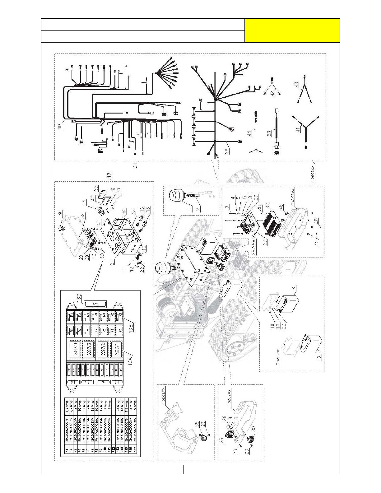
44
ELECTRICAL COMPONENTS
ROBOCUT
McCONNEL
Page 98
45
ELECTRICAL COMPONENTS
ROBOCUT
McCONNEL
REF. QTY. PART No. DESCRIPTION
ELECTRICAL COMPONENTS (Continued)
41 1 4000329 BATTERY CABLE - POSITIVE (+)
42 1 4000330 BATTERY CABLE - NEGATIVE (-)
43 1 4000331 STARTER MOTOR/ALTERNATOR POWER LINE
44 1 4000838 SWITCH
45 4 4000114 WASHER
46 4 4000839 ANTI-VIBRATION
47 4 4000840 SCREW
48 4 4000841 NUT
49 1 4000842 DISPLAY FASTENING
50 4 4000841 NUT
51 1 4000843 SOUNDPROOF BOX PROTECTION
52 1 4000844 INNER SOUNDPROOF BOX PROTECTION
53 1 4000847 REMOTE CONTROL LINE
Page 99

46
ELECTRICAL WIRING
ROBOCUT
McCONNEL
Page 100
47
REF. QTY. PART No. DESCRIPTION
ELECTRICAL WIRING
1 4 4000477 CONNECTOR
2 2 4000478 CONNECTOR
3 11 4000479 CONNECTOR
4 2 4000480 CONNECTOR
5 1 4000481 CONNECTOR
6 1 4000482 CONNECTOR
7 1 4000483 CONNECTOR
8 2 4000484 CONNECTOR
9 1 4000485 CONNECTOR
10 5 4000486 CONNECTOR
11 7 4000487 RUBBER CABLE SLEEVE
12 7 4000337 CONNECTOR
13 1 4000837 WIRING LOOM - CHASSIS LINE
14 2 4000488 CONNECTOR
15 1 4000489 CONNECTOR
16 1 4000490 CONNECTOR
17 1 4000491 RUBBER COVER
18 2 4000492 CONNECTOR
19 1 4000833 WIRING LOOM - CONTROL UNIT
20 1 4000329 BATTERY CABLE - POSITIVE (+)
21 1 4000330 BATTERY CABLE - NEGATIVE (-)
22 1 4000331 STARTER MOTOR/ALTERNATOR POWER LINE
23 1 4000838 SWITCH
24 1 4000826 WIRING LOOMS - ELECTRICAL SYSTEM
25 1 4000845 CONNECTOR
26 1 4000846 CONNECTOR
27 1 4000847 REMOTE CONTROL LINE
28 1 4000477 CONNECTOR
29 1 4000846 CONNECTOR
30 1 4000848 CONNECTOR
ELECTRICAL WIRING
ROBOCUT
McCONNEL
 Loading...