

McCall Refrigeration MCCR48, MCCSTF48, MCCSTR27 User Manual
Compact Refrigerators & Freezers
Service, Installation and Care Manual
Please read this manual completely before attempting to install or operate this equipment!
Notify carrier of damage! Inspect all components immediately. See page 3.
IMPORTANT INFORMATION
READ BEFORE USE
PLEASE SAVE THESE INSTRUCTIONS!
May 2011

Compact Refrigerators and Freezers Service and Installation Manual
Contents
Receiving & Inspecting Equipment ................................................. 2
Specifications .................................................................................. 3
Installation ...................................................................................... 3
Caster Installation ........................................................................... 4
Caster/Leg Mounting Detail ............................................................ 4
Refrigeration Operation ................................................................... 5
Evaporator Fan Operation ............................................................... 5
Freezer Operation ............................................................................ 6
Door Hinge Reversal Instructions ................................................... 7
Door Hinge Reversal Templates ...................................................... 8
Maintenance ...............................................................................9-10
Refrigerator Wiring Diagram ......................................................... 11
Refrigerator Replacement Parts .................................................... 11
Freezer Wiring Diagram ................................................................ 12
Freezer Replacement Parts ........................................................... 12
Standard Labor Guidelines ............................................................ 13
Manufacturers Limited Warranty .................................................. 14
Standard Warranties ..................................................................... 15
Serial Number Location
The serial number is located on the right side interior back wall
or under the top nosing directly above the right door.
Always have the serial number of your unit available when calling
for parts or service. A complete list of authorized McCall parts
depots is on www.mccallrefrigeration.com.
This manual covers standard units only. If you have a custom
unit, consult the customer service department at 1-888-7322446
©2011 McCall. All rights reserved. Reproduction without written permission
is prohibited.
Receiving And Inspecting The Equipment
Even though most equipment is shipped crated, care should
be taken during unloading so the equipment is not damaged
while being moved into the building.
1. Visually inspect the exterior of the package and skid or
container. Any damage should be noted and reported to
the delivering carrier immediately.
2. If damaged, open and inspect the contents with the
carrier.
3. In the event that the exterior is not damaged, yet upon
opening, there is concealed damage to the equipment
notify the carrier. Notification should be made verbally
as well as in written form.
4. Request an inspection by the shipping company of the
damaged equipment. This should be done within 10 days
from receipt of the equipment.
5. Check the lower portion of the unit to be sure legs or
casters are not bent.
6. Be sure to check the compressor compartment housing
and visually inspect the refrigeration package. Be sure
lines are secure and base is still intact.
7. Freight carriers can supply the necessary damage forms
upon request.
8. Retain all crating material until an inspection has been
made or waived.
2
For customer service, call (888) 732-2446 Fax (800) 669-0619, www.mccallrefrigeration.com
Compact Refrigerators and Freezers Service and Installation Manual
CAUTION
Specifications
Work top refrigerator or freezer bases with stainless steel top & backsplash
Model Description L D H Volume Ft.3Shelf Area Ft.2H.P. Refg. Charge Amp NEMA Plug Ship Weight
MCCSTR27 refrigerator 27.00”
MCCSTF27 freezer 27.00”
MCCSTR48 refrigerator 48.00”
MCCSTF48 freezer 48.00”
Undercounter refrigerator or freezer bases with stainless steel top
Model Description L D H Volume Ft.3Shelf Area Ft.2H.P. Refg. Charge Amp NEMA Plug Ship Weight
MCCR27 refrigerator 27.00”
MCCF27 freezer 27.00”
MCCR48 refrigerator 48.00”
MCCF48 freezer 48.00”
(69cm)
(69cm)
(122cm)
(122cm)
(69cm)
(69cm)
(122cm)
(122cm)
28.50”
(72cm)
28.50”
(72cm)
28.50”
(72cm)
28.50”
(72cm)
28.50”
(72cm)
28.50”
(72cm)
28.50”
(72cm)
28.50”
(72cm)
39.50”
(100cm)
39.50”
(100cm)
39.50”
(100cm)
39.50”
(100cm)
35.50”
(90cm)
35.50”
(90cm)
35.50”
(90cm)
35.50”
(90cm)
5.7 4.6 1/5 7.0 4.0 5-15P 176lbs
5.7 4.6 1/5 7.0 5.8 5-15P 184lbs
10.8 8.0 1/5 7.0 4.0 5-15P 234lbs
10.8 8.0 1/3 7.0 5.6 5-15P 242lbs
5.7 4.6 1/5 7.0 4.0 5-15P 176lbs
5.7 4.6 1/5 7.0 5.8 5-15P 176lbs
10.8 8.0 1/5 7.0 4.0 5-15P 236lbs
10.8 8.0 1/3 7.0 5.6 5-15P 236lbs
(80kg)
(83kg)
(106kg)
(110kg)
(80kg)
(80kg)
(107kg)
(107kg)
Installation
Location
Units represented in this manual are intended for indoor use
only. Be sure the location chosen has a floor strong enough to
support the total weight of the cabinet and contents. Reinforce the
floor as necessary to provide for maximum loading.
For the most efficient refrigeration, be sure to provide good air
circulation inside and out.
Inside cabinet: Do not pack refrigerator so full that air cannot
circulate.
Outside cabinet: Be sure that the unit has access to ample
air. A minimum space of 3” (7.6cm) at the back of the unit
and 1” (2.5cm) at the top and sides is required to conform to
Underwriters Laboratories’ standards. On undercounter units it is
imperative that the proper air flow be maintained. The refrigeration
system is designed so air will flow under the unit, over the
compressor/condenser area, and out at the top rear of the unit.
Avoid hot corners and locations near stoves and ovens.
Any restriction of the proper air flow outlined
above, total or partial, will void the warranty on
the unit.
Leveling
A level cabinet will perform better because the drain pan will drain
properly, the doors will line up with the frames and the cabinet will
not be subject to undue strain.
All four legs are adjustable. Adjust each leg until the unit is stable
and level left to right. If necessary adjusting the front legs slightly
higher than the rear by about 1/8” (0.3cm) will help the doors
remain closed.
If the unit is supplied with casters, no adjustments are available.
Ensure the floor where the unit is to be located is level.
Never stand on the unit! Doing so may result in bodily
injury. They are not designed to hold the weight of
an adult and will collapse if misused in this manner.
Stabilizing
Some models are supplied on casters for your convenience, for
ease of cleaning underneath and mobility.
The unit must be installed in a stable condition
with the front wheels locked. Locking the front
casters after installation is the owner’s and operator’s
responsibility.
Plumbing
Self-contained models are standard with a condensate evaporator.
If, for some reason, a unit does not have a condensate evaporator,
or the evaporator fails, the unit’s drain must have an outlet to an
appropriate drainage area or container.
Moisture collecting from improper drainage can
create a slippery surface on the floor and a hazard to
employees. It is the owner’s responsibility to provide
a container or outlet for drainage.
Electrical connection
Refer to the amperage data on page 3, the serial tag, your
local code or the National Electrical Code to be sure the unit is
connected to the proper power source. A protected circuit of the
correct voltage and amperage must be run for connection of the
line cord, or permanent connection to the unit.
A 6’ (1.8 m) long grounded supply cord and plug are provided
with standard units. Simply plug the unit in to begin operation.
The thermostat must be turned to OFF and the unit
disconnected from the power source whenever
performing service, maintenance functions or
cleaning the refrigerated area.
For customer service, call (888) 732-2446, Fax (800) 669-0619, www.mccallrefrigeration.com
3
Compact Refrigerators and Freezers Service and Installation Manual
Plate Casters
W/Locks
Plate Casters
W/O Locks
#14 x .75" Hex Head
Screws #932-1116
WARNING
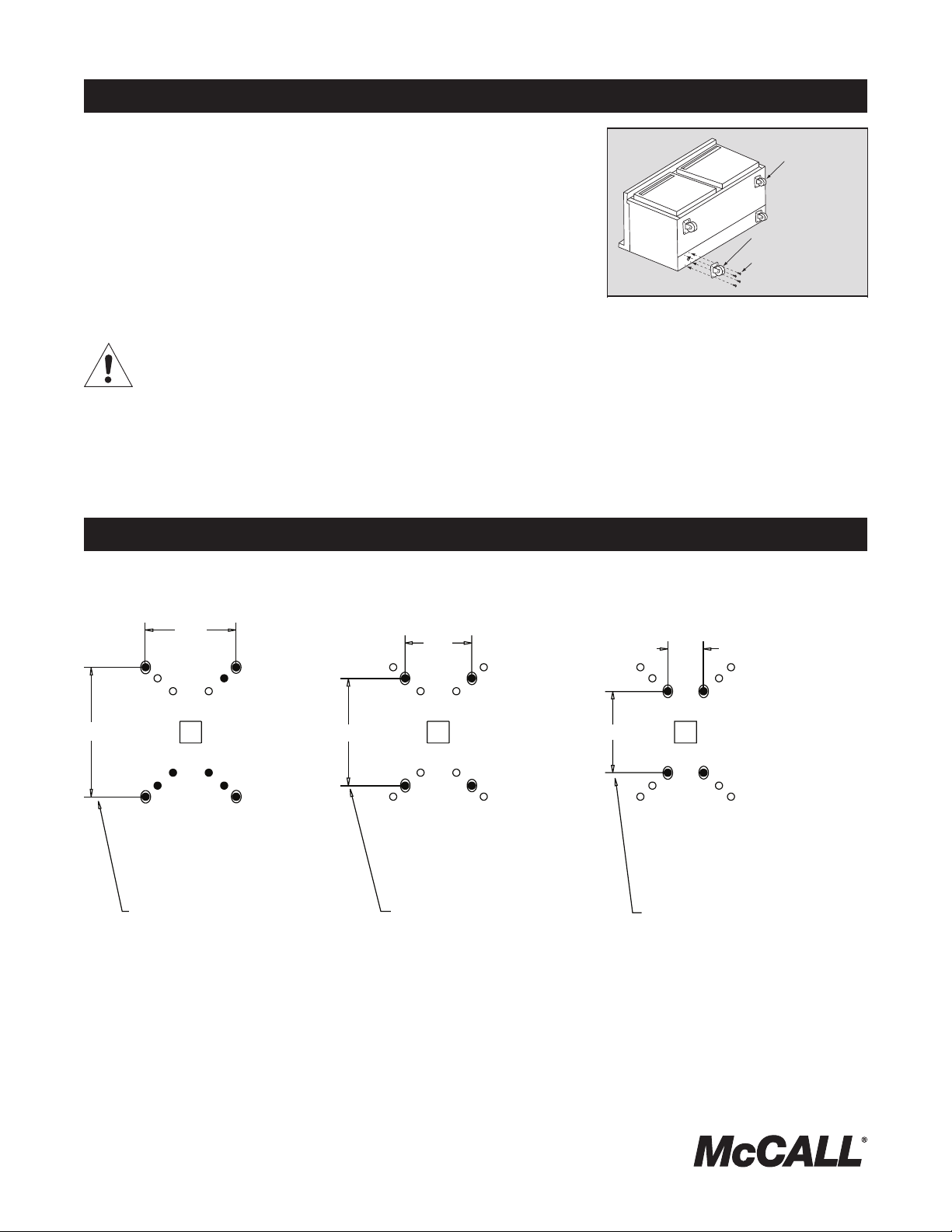
Caster Installation
1. Carefully place the unit on its back (see illustration at right).
2. Remove legs by unscrewing them in a counter clockwise direction.
3. Located on each end of the compressor channel are 4 hex head screws, for a total of
8 screws. Remove them. 8 additional screws are provided with your casters.
4. Place a locking plate caster over one of the front holes, matching the 4 mounting
holes to the pre-drilled holes in the underside of the unit. Insert 4 hex head screws
and tighten. Repeat with the other locking front casters.
5. Repeat step 4 with the non-locking casters in the rear of the unit.
6. Carefully lift the unit upright.
After installing casters, the unit must stand upright for twenty-four (24)
hours before being powered up to assure oil return to the compressor
sump.
2”, 3” and 5” Caster and Leg Mounting Detail
A universal bolt hole pattern is provided on the bottom of the cabinet. It will accommodate any leg or caster. Simply line up the plate
holes with the corresponding cabinet holes.
3.40”
2.38”
2.82”
NOTE:
If hole pattern on caster/
leg matches the one above
mount in outer set of holes.
1.75”
2.14”
NOTE:
If hole pattern on caster/leg
matches the one above mount
in middle set of holes.
0.94”
NOTE:
If hole pattern on caster/leg
matches the one above mount
in inner set of holes.
6” Leg - 3234569
3” Caster - 3234024
2” Caster - 3234148
5” Caster - 3234161
4
For customer service, call (888) 732-2446 Fax (800) 669-0619, www.mccallrefrigeration.com
Refrigerator Temperature Control Operation
Compact Refrigerators and Freezers Service and Installation Manual
After the unit is connected to power it will automatically begin
operating. With the doors closed, the temperature of the
cabinet should reach 36°F to 40°F (2°C to 4°C) on refrigerators
in about one hour.
A thermostat located in the evaporator housing on interior rear
of the unit, controls the temperature in the box. The factory
setting for the control is “4” and maintains about 38°F (3°C)
in the box. Set toward “1” for higher temperatures and toward
“7” for lower temperatures.
Continuous opening and closing of the doors will hamper the
unit’s ability to maintain optimum refrigeration temperature.
Refrigerators defrost automatically with every cycle of the
compressor. The water generated is routed to a pan on the
rear of the unit and is evaporated by the heat given off by the
compressor.
Service Alert
During normal operation the evaporator fan may cycle
and/or pulse independently of the compressor. Consult
the service manual or contact Technical Support at
1-888-732-2446 if you are unsure of the proper function.
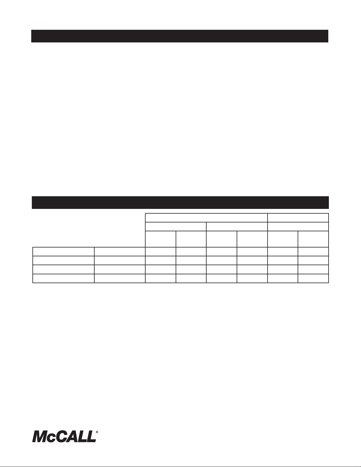
Evaporator Fan Operation
Cooling Cycle Defrost Cycle
Compressor On Compressor Off Compressor Off
Evap Fan OnEvap Fan
Off
MCCSTR27 MCCR27 Refrigerator X X X
MCCSTF27 MCCF27 Freezer X X X
MCCSTR48 MCCR48 Refrigerator X X X
MCCSTF48 MCCF48 Freezer X X X
Evap Fan OnEvap Fan
Off
Evap Fan OnEvap Fan
Off
For customer service, call (888) 732-2446, Fax (800) 669-0619, www.mccallrefrigeration.com
5
 Loading...