

Page 1
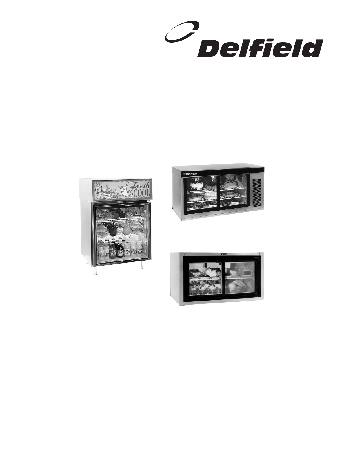
Display Cases
Service and Installation Manual
Please read this manual completely before attempting to install or operate this equipment!
Notify carrier of damage! Inspect all components immediately. See page 2.
Model 724, 7000, and 9000 Series
Effective May 2002
Page 2
Display Cases 724, 7000, 9000 Series Service and Installation Manual
Display Cases 724, 7000, 9000 Series Service and Installation Manual
3
For customer service, call (800) 733-8829, (800) 773-8821, Fax (989) 773-3210, www.deleld.com
CONTENTS
RECEIVING AND INSPECTING ..............................................3
INSTALLATION......................................................................3
WALL MOUNT INSTALLATION..............................................4
WIRING DIAGRAMS .............................................................5
OPERATION ..........................................................................6
MAINTENANCE .....................................................................6
REPLACEMENT PARTS
7000 SERIES .................................................................7
MODEL 724 ...................................................................7
PIKE®-STYLE DOORS ................................................ 8-9
9000 SERIES ...............................................................10
TROUBLESHOOTING REFERENCE ......................................11
STANDARD WARRANTIES ............................................ 12-13
AUTHORIZED PARTS DEPOTS...............................back cover
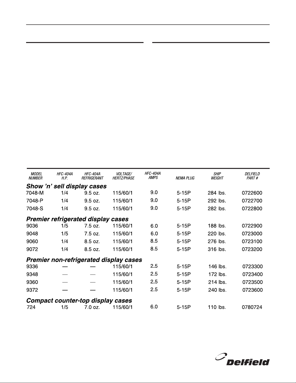
SPECIFICATIONS
SERIAL NUMBER LOCATION
724
Located on rear shroud panel below the power switches and
thermostat.
7000 & 9000
Located on the inside light xture on the right hand side.
Always have the serial number of your unit available when
calling for parts or service. A complete list of authorized parts
depots is shown on the back cover of this manual.
©2000 The Delfield Company. All rights reserved. Reproduction without
written permission is prohibited.
“Delfield” is a registered trademarks of The Delfield Company.
2
For customer service, call (800) 733-8829, (800) 773-8821, Fax (989) 773-3210, www.deleld.com
Page 3
Display Cases 724, 7000, 9000 Series Service and Installation Manual
RECEIVING AND INSPECTING THE EQUIPMENT
Even though most equipment is shipped crated, care should be
taken during unloading so the equipment is not damaged while
being moved into the building.
Carefully check for any visible signs of damage to the cartons or
containers. If evidence of damage exists, the package should be
opened immediately and a joint inventory and examination of the
contents should be made by you and the driver. Sign delivery
receipt as damaged. Example— if (2) pieces of (5) are damaged, you must indicate the number of units damaged.
Concealed damage
If a concealed loss or damage is discovered after you have
given the carrier a clear delivery receipt, notify the carrier
in writing immediately or within 10 days from the delivery
INSTALLATION
Location
Deleld 7000 and 9000 Series and Model 724 display cases
should be installed on a level surface away from any source
of intense heat such as ovens or ranges. Do not install 9000
Series units closer than 6" (15.2 cm) from the ceiling or
counter. This will allow air ow to the machine compartment.
The 724 should be installed on legs as provided (4" [10.2 cm]
from the counter).
When using a Model 724 display case, never obstruct the
ow of air to the top of the cabinet. Do not place or store any
items on top surface of unit. Obstruction of air may cause
damage to the compressor.
On 7000 Series pass-through or see-through units, the cabinet can be installed with the machine compartment side ush
against a wall or obstruction as long as both the front and
the rear louvers are unobstructed. Do not install 7000 Series
mirrored units closer than 6" (15.2 cm) from the wall.
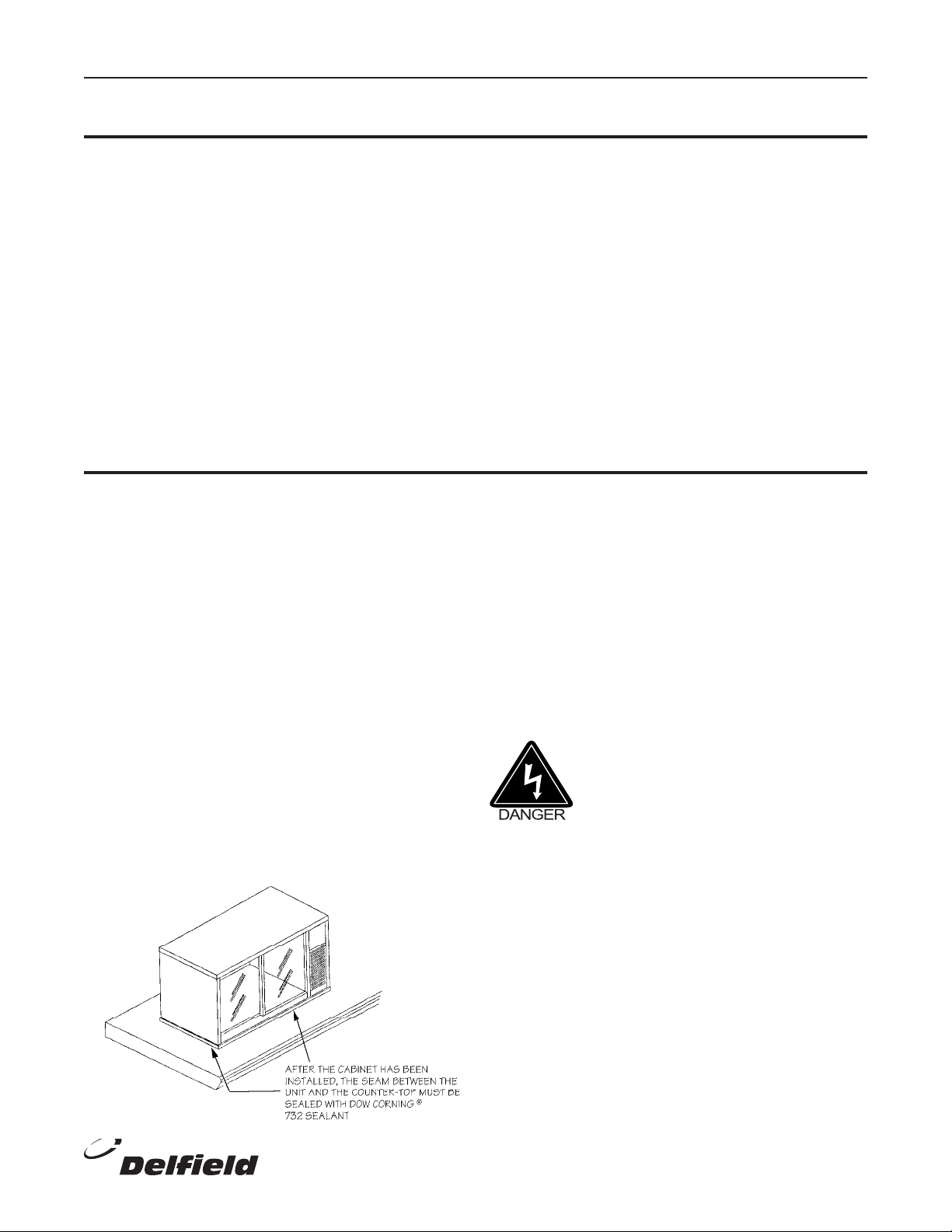
If installing a 7000 Series display case into a counter-top, you
must seal the perimeter of the equipment with silicone sealant (see diagram below).
date. If you phone the carrier, you must follow up the call
in writing to protect your rights. You can only improve your
position as a claimant by promptly reporting such loss or
damage. You should also retain all cartons or containers,
including packing material, until an inspection has been
made or waived.
Filing a claim
Notation of loss or damage does not constitute the ling of
a claim. You should le your claim in writing with the carrier
immediately!
Carriers will furnish the necessary form upon request. You
should also request an inspection. If a claim is led by phone,
always follow up immediately in writing.
For the most efcient refrigeration, be sure to provide good
air circulation inside and out. Take care not to block air ow
to the fans and allow space along the sides.
Do not pack the interior of the display case so full that air
cannot circulate.
Leveling
A level cabinet looks better and will perform better because
the doors will line up with the door frames properly, and the
cabinet will not be subject to unnecessary strain.
Electrical connection
Refer to the amperage data on page 2 or the
serial tag data and your local code or the
National Electrical Code to be sure the unit
is connected to the proper power source. A
protected circuit of the correct voltage and
amperage must be run for connection of the
line cord or permanent connection to the
unit.
The power should be disconnected whenever performing maintenance or repair
functions. Failure to observe this warning
may result in electrical shock and personal
injury!
For customer service, call (800) 733-8829, (800) 773-8821, Fax (989) 773-3210, www.deleld.com
3
Page 4
Display Cases 724, 7000, 9000 Series Service and Installation Manual
Display Cases 724, 7000, 9000 Series Service and Installation Manual
5
For customer service, call (800) 733-8829, (800) 773-8821, Fax (989) 773-3210, www.deleld.com
ST PE S
S
T PE
S
WALL MOUNT INSTALLATION
7000 Series
The optional wall mount kit is designed to securely hold a
7000 Series unit to a structurally sound wall. It meets the
requirements as established by Underwriter’s Laboratories
of withstanding a static load of four times the weight of the
cabinet alone.
The Deleld Company cannot assume
any responsibility for damage to a wall
or injury of any persons should the wall
fail as a result of the unit’s weight. Nor
will The Deleld Company assume any
responsibility for damage or injury as a
result of the wall mount xture failing if it is
determined that the installation instructions
were not properly followed.
List of materials
2 — 2" x 2" x 3/16" (5.1 cm x 5.1 cm x 0.2 cm) angled
aluminum brackets, 48" (121.9 cm) long
12 — #10 x 7/8" type A hex head metal screws
6 — 1/4" x 2–1/2" lag bolts
2 — stainless steel trim pieces
1 Position the prepunched aluminum bracket
on the top of the unit, flush with the back
edge, and mark the location of the holes
on the unit. There should be one hole
approximately 5/8" (1.6 cm) from each end
of the cabinet, and a third hole 8.75" (22.2
cm) from the right end of the cabinet. Be
sure to use the prepunched holes; screws
in these locations tie into the internal
support structure of the unit.
2 Drill 9/64" (3.6 mm) holes at the locations
as marked. Attach the bracket to the unit
with three of the #10 sheet metal screws.
3 Mount the bottom bracket to the wall.
On a stud wall, the bottom bracket should be screwed into a
minimum of three studs with the provided 1/4" x 2–1/2" lag
bolts. On a masonry block wall, the bottom bracket should be
screwed into the wall at a minimum of three evenly spaced
locations with 1/4" diameter toggle bolts (not provided).
When positioning the bottom bracket, be sure to allow at
least 6" (15.2 cm) of clearance above and below the unit. Be
sure the bottom bracket is level before continuing.
4 Position the unit on the bottom bracket and
attach the top bracket to the wall using the
same method as in step 3.
5 Attach the bottom bracket to the unit using
the prepunched holes and three of the #10
sheet metal screws.
6 Attach the stainless steel trim strips to the
left and right sides of the cabinet using
three #10 metal screws on each side.
9000 Series
The Deleld Company cannot assume
any responsibility for damage to a wall
or injury of any persons should the wall
fail as a result of the unit’s weight. Nor
will The Deleld Company assume any
responsibility for damage or injury as a
result of the wall brackets failing if it is
determined that the installation instructions
were not properly followed.
When choosing a location to mount your 9000 Series display
case, keep in mind that the entire unit must be removed from
the wall in order to clean the condenser. This must be done
on a regular basis, in most cases not longer than every three
months. Install the equipment in a location that will allow
easy removal for cleaning.
1 Two wall brackets are supplied with 36" and 48"
long units; three brackets are supplied with 60"
and 72" long units. Lag bolts are not supplied
(see below for recommended sizes). Use all
brackets provided for a secure installation.
On a stud wall, the brackets should be screwed into two
studs with 1/4" lag bolts so that 2.50" (6.4 cm) of the lag
bolt engages the stud. On a masonry block wall, the brackets
should be screwed into the wall at two evenly spaced locations with 1/4" diameter toggle bolts.
When positioning the brackets, be sure to allow at least 6"
(15.2 cm) of clearance above and below the unit.
2 After the brackets are attached to the wall
with one bolt in each, check that they are
level. Finish mounting the brackets.
3 Once the brackets are secure, lift the unit
into place and engage the angle bracket on
the back of the unit into the wall brackets.
4
For customer service, call (800) 733-8829, (800) 773-8821, Fax (989) 773-3210, www.deleld.com
Page 5
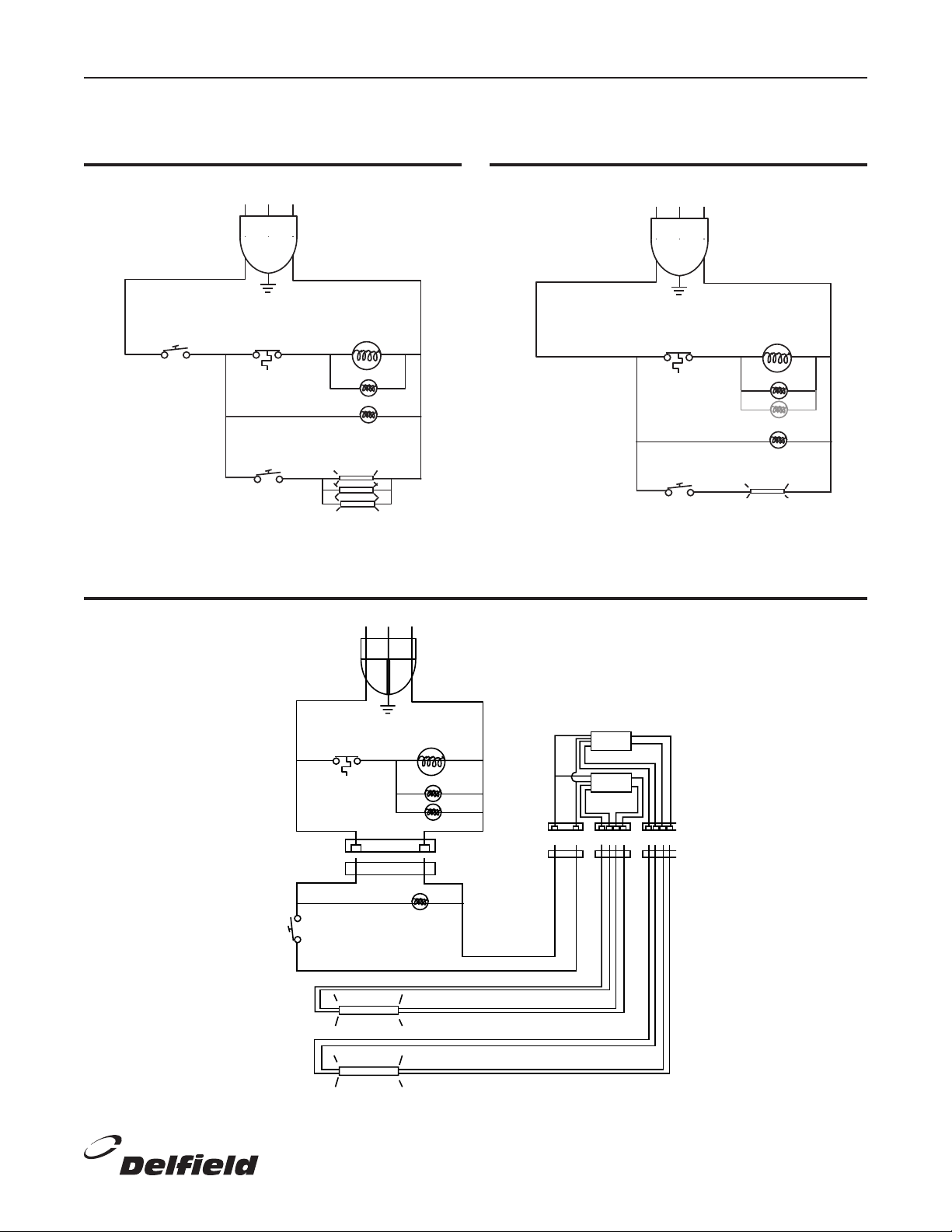
Display Cases 724, 7000, 9000 Series Service and Installation Manual
G
COMPRESSOR
WIRING
DIAGRAM FOR
115V/60Hz/1 ph
9000 SERIES
BLACK
WHITE
CONDENSER FANS
(2 on 9060 & 9072)
EVAPORATOR FAN
TEMPERATURE
CONTROL
LIGHT SWITCH
LIGHT
LIGHTS
G
COMPRESSOR
WIRING
DIAGRAM FOR
115V/60Hz/1 ph
MODEL 724
POWER
SWITCH
BLACK
WHITE
CONDENSER FAN
EVAPORATOR FAN
TEMPERATURE
CONTROL
LIGHT
SWITCH
G
COMPRESSOR
WIRING
DIAGRAM FOR
115V/60Hz/1 ph
7000 SERIES
BLACK WHITE
CONDENSER FANS
EVAPORATOR FAN
TEMPERATURE
CONTROL
LIGHT SWITCH
FLUORESCENT LAMPS
WHITE
BLACK
WALL
PLUG
BALLASTS
WALL
PLUGS
WIRING DIAGRAM—
MODEL 724
WIRING DIAGRAM—
9000 SERIES
WIRING DIAGRAM—7000 SERIES
For customer service, call (800) 733-8829, (800) 773-8821, Fax (989) 773-3210, www.deleld.com
5
Page 6

Display Cases 724, 7000, 9000 Series Service and Installation Manual
Display Cases 724, 7000, 9000 Series Service and Installation Manual
7
For customer service, call (800) 733-8829, (800) 773-8821, Fax (989) 773-3210, www.deleld.com
ST PE S
ST PE S
OPERATION
The units are self-defrosting. They do not require any manual
defrosting. During normal operation, the coil will defrost
automatically whenever the compressor is not operating.
In high humidity areas frost will accumulate on the coil,
reducing the heat transfer that takes place. When this occurs,
the system is designed to sense the frost build-up and shut
off the compressor, thereby allowing it to defrost. Under
these conditions, cabinet temperatures may be warmer than
normal. This is not cause for alarm, but merely indicative of a
properly functioning unit in high humidity conditions.
The unit is set at the factory to maintain between 36°F to
40°F (2°C to 4°C) and should require no adjustments on
initial start-up. If temperatures are not satisfactory adjust the
MAINTENANCE
Cleaning the unit
The interior and exterior can be cleaned using soap and warm
water. If this is not sufcient try ammonia and water or a
non-abrasive liquid cleaner.
When cleaning the exterior, always rub with the “grain” of
the stainless steel to avoid marring the nish. Do not use an
abrasive cleaner because it will scratch the stainless steel and
plastic.
The sign insert on Model 724 units is easily removable for
cleaning or replacement:
1 Remove the screws that attach the
perforated top to the unit.
2 Lift off the perforated top and set it aside.
3 Facing the front of the unit, grasp the sign
securely and lift it up and out of the “U”-
shaped channel that holds it in place.
4 Clean with a mild soap and warm water,
and allow the sign to dry thoroughly.
5 Reinsert the sign into the “U”-shaped
channel.
6 Re-attach the perforated top with the
screws.
Doors
To remove the Pike®-style doors on the 7000 and 9000
Series, follow these steps:
1 Open the right-hand (outer) sliding door
about 2" to 4" (5 cm to 10 cm).
2 Lift the door vertically far enough to clear
the bottom track.
3 Pull the door towards you and remove it.
4 Repeat steps 1 through 3 for the left-hand
(inner) door.
temperature control. Turning the knob clockwise will make
the cabinet colder.
The temperature control on the 9000 Series is located inside
the cabinet near the top.
The temperature control on the 7000 Series is located behind
the front louvered panel.
The temperature control on Model 724 units is on the back of
the unit in the top left hand corner.
Model 724 units have a main switch that shuts off the entire
unit. The light switch shuts off all three lights. The temperature control will shut off the condensing unit.
Condensing unit
The power must be disconnected
before doing any maintenance to the
condensing unit. Failure to observe this
warning may result in electrical shock
and personal injury.
In order to maintain proper refrigeration performance, the
condenser ns must be cleaned of dust, dirt, and grease
regularly. It is recommended that this be done at least every
three months. If conditions are such that the condenser is
totally blocked in three months, the frequency of cleaning
should be increased.
Clean the condenser with a vacuum cleaner or stiff brush. If
extremely dirty a commercially available condenser cleaner
may be required.
Door gaskets
The door gaskets should be cleaned as required to maintain their ability to seal properly. Do not use sharp tools or
knives to scrape the bellows as this may tear the gasket and
eliminate its ability to seal. A soft bristle brush and solution
of soap and water should be all that is required to keep the
gaskets clean. Do not use full strength de-greasing agents
on the gasket as they could cause the gasket to crack and
become brittle.
To help prevent the blower coil from becoming corroded,
store all acidic items in sealed containers, and immediately
wipe up all spills.
6
For customer service, call (800) 733-8829, (800) 773-8821, Fax (989) 773-3210, www.deleld.com
Page 7

Display Cases 724, 7000, 9000 Series Service and Installation Manual
REPLACEMENT PARTS—MODEL 724
(HFC-404A)
The following replacement parts are for use with Model 724
units using HFC-404A refrigerant only.
Ballast ..................................................................... 219-4161
Bracket assembly, fan, cond. .................................. 033-0146
Capillary tubing (84" of .044) .................................. 007-4100
Compressor, 1/5 h.p., 404A ....................................352-6875
Coil, condenser ....................................................... 351-6241
Coil, evaporator....................................................... 351-6240
Door assembly, hinged glass, left ........................... 323-4686
Door assembly, hinged glass, right......................... 323-4673
Evaporator, hot gas ................................................. 005-3565
Fan blade, 5.5"......................................................... 351-6289
Fan motor, 120V ..................................................... 216-2697
Heat exhanger......................................................... 034-0242
Hinge, bottom of door............................................. 323-4687
Hinge, top of door................................................... 323-4688
Housing, evaporator................................................ 034-0226
Lamp, uorescent, 18", F15T8/D (coated)............... 219-4290
Lamp holder, left ..................................................... 219-3939
Lamp holder, right................................................... 219-3940
Leg, chrome plated, 4" ............................................ 323-4685
Pan, condensate...................................................... 005-5200
Pan, drain, plastic ...................................................170-2247
Pigtail, light xture, 18"........................................... 218-3410
Screen, intake .........................................................397-7989
Screw, wing, almond............................................... 932-1009
Shelf, almond.......................................................... 397-7990
Sign, “Beverage”..................................................... 170-1037
Sign, blank.............................................................. 170-1035
Sign, “Fresh 'n' Cool”.............................................. 170-1038
Sign, “Salad”........................................................... 170-1039
Sign, “Sandwich”.................................................... 170-1036
Switch, ON/OFF rocker............................................ 219-0154
Temperature control................................................ 219-4224
Thermometer, 4" ..................................................... 351-6135
Gasket..................................................................... 170-1215
REPLACEMENT PARTS— 7000 SERIES
(HFC-404A)
The following replacement parts are for use with 7000 Series
units using HFC-404A refrigerant only.
Accumulator, vertical, 4" ......................................... 351-6186
Air diffuser .............................................................. 005-4638
Ballast ..................................................................... 219-3998
Bearing, Pike®-style doors .....................................see page 8
Capillary tube (96" of .044) .....................................007-4061
Coil, condenser ....................................................... 351-6259
Coil, evaporator....................................................... 351-6260
Compressor, 1/4 hp., 404A .....................................352-6877
Door assembly, complete........................................ 345-5450
End panel, stainless steel........................................ 005-6510
Evaporator, hot gas ................................................. 005-3542
Fan assembly, condenser........................................ 038-0316
Fan blade, condenser .............................................. 351-6172
Fan blade, evaporator.............................................. 351-6172
Fan guard, evaporator............................................. 351-6173
Fan motor, condenser ............................................. 216-2691
Fan motor, evaporator............................................. 216-2691
Fluorescent bulb, 36" .............................................. 219-4359
Glass, rear, 7048-S ................................................. 345-5456
Lamp holder............................................................ 219-4061
Legs (optional)........................................................ 323-4394
Louver, machine compartment front ....................... 005-6536
Mirror...................................................................... 345-5421
Shelf Beige.............................................................. 397-8054
Temperature control................................................ 219-4224
Top, stainless steel.................................................. 005-6537
Trim, label, name plate ............................................ 323-4120
Wall mount kit......................................................... 038-0123
Thermometer, 4" ..................................................... 351-6135
For individual replacement parts for Pike®-style doors, see page 8.
Parts lists cover current models only. Contact Deleld for units using other refrigerants. • Before any labor to be done under warranty is
performed, be sure the service agent has obtained a Deleld Service Work Authorization Number.
For customer service, call (800) 733-8829, (800) 773-8821, Fax (989) 773-3210, www.deleld.com
7
Page 8

Display Cases 724, 7000, 9000 Series Service and Installation Manual
Display Cases 724, 7000, 9000 Series Service and Installation Manual
9
For customer service, call (800) 733-8829, (800) 773-8821, Fax (989) 773-3210, www.deleld.com
REPLACEMENT PARTS — PIKE® STYLE DOORS
7048-M/7048-P/7048-S
Complete door assembly ........................................ 345-5450
1. Bearing, roller, single (2 per door) ......................323-4636
2. Gasket, bumper, 9 9/16"...................................... 323-3927
3. Gasket, wiper strip, 18 1/8"................................. 323-3935
4. Spring, 15" green ................................................ 323-3948
5. Track, bottom, 37 5/8"......................................... 323-3901
6. Track, top, 37 5/8" ............................................... 323-3914
9036
Complete door assembly ........................................ 345-5452
1. Bearing, roller, single (2 per door) ......................323-4636
2. Gasket, bumper, 15 1/8"...................................... 323-3926
3. Gasket, wiper strip, 13 11/16"............................. 323-3934
4. Spring, 12" Green................................................ 323-3947
5. Track, bottom, 32"............................................... 323-3900
6. Track, top, 33" ..................................................... 323-3913
9060
Complete door assembly ........................................ 345-5454
1. Bearing, roller, single, (2 per door) .....................323-4636
2. Gasket, bumper, 15 1/8"...................................... 323-3926
3. Gasket, wiper strip, 13 11/16"............................. 323-3934
4. Spring, 23" green ................................................ 323-3950
5. Track, bottom, 56"............................................... 323-3908
6. Track, top, 57" ..................................................... 323-3921
9048
Complete door assembly ........................................ 345-5453
1. Bearing, roller, single (2 per door) ......................323-4636
2. Gasket, bumper, 15 1/8"...................................... 323-3926
3. Gasket, wiper strip, 13 11/16"............................. 323-3934
4. Spring, 19" green ................................................ 323-3949
5. Track, bottom, 44"............................................... 323-3903
6. Track, top, 45" ..................................................... 323-3916
9072
Complete door assembly ........................................ 345-5455
1. Bearing, roller, single, (2 per door) .....................323-4636
2. Gasket, bumper, 15 1/8"...................................... 323-3926
3. Gasket, wiper strip, 55 3/8"................................. 323-3941
4. Spring, 30" gold .................................................. 323-3946
5. Track, bottom, 68"............................................... 323-3911
6. Track, top, 69" ..................................................... 323-3924
Parts lists cover current models only. Contact Deleld for units using other refrigerants. • Before any labor to be done under warranty is
performed, be sure the service agent has obtained a Deleld Service Work Authorization Number.
8
For customer service, call (800) 733-8829, (800) 773-8821, Fax (989) 773-3210, www.deleld.com
Page 9

Display Cases 724, 7000, 9000 Series Service and Installation Manual
4
6
4
3
1
1
1
1
5
2
2
REPLACEMENT PARTS—PIKE®-STYLE DOORS
All Deleld 7000 and 9000 Series display cases feature
easily-removable doors manufactured by Pike®. These doors
allow simple cleaning and maintenance, as well as easier
replacement if the glass is cracked or broken.
Individual replacement parts for these Pike-style doors are
not stocked at the Deleld Authorized Parts Depots. They
must be obtained directly from Deleld. Use the diagram
below to identify the part you need (see page 8 for parts listing). Then call Deleld Customer Service at (800) 733-8829
with the model and serial number of your equipment.
For customer service, call (800) 733-8829, (800) 773-8821, Fax (989) 773-3210, www.deleld.com
9
Page 10

Display Cases 724, 7000, 9000 Series Service and Installation Manual
Display Cases 724, 7000, 9000 Series Service and Installation Manual
11
For customer service, call (800) 733-8829, (800) 773-8821, Fax (989) 773-3210, www.deleld.com
REPLACEMENT PARTS — 9000 SERIES (HFC-404A)
The following replacement parts are for use with 9000 Series units using HFC-404A refrigerant only.
9036 9048 9060 9072
Accumulator............................................................ 351-6051 X X X X
Ballast ..................................................................... 219-3998 X X X
Ballast ..................................................................... 219-4161 X
Bracket, mounting, condensing fan motor.............. 038-2055 X X X X
Bracket, mounting, evaporator fan motor ...............397-8060 X X X X
Bracket, wall mount ................................................005-1232 X X X X
Capillary tube (132" of .044) ................................................... X X
Capillary tube (96" of .044) ..................................................... X X
Coil, condenser ....................................................... 351-6263 X X
Coil, condenser ....................................................... 351-6264 X X
Coil, evaporator....................................................... 351-6261 X X
Coil, evaporator....................................................... 351-6262 X X
Compressor, 1/4 h.p., 404A ....................................352-6877 X X
Compressor, 1/5 h.p., 404A ....................................352-6875 X X
Door assembly, Pike®-style complete ..................... 345-5452 X
Door assembly, Pike®-style complete ..................... 345-5453 X
Door assembly, Pike®-style complete ..................... 345-5454 X
Door assembly, Pike®-style complete ..................... 345-5455 X
Fan blade, condenser .............................................. 351-6274 X X X X
Fan blade, evaporator.............................................. 216-2500 X X X X
Fan guard, condenser ............................................. 351-6178 X X X X
Fan guard, evaporator............................................. 351-6185 X X X X
Fan motor, condenser ............................................. 216-2691 X X X X
Fan motor, evaporator............................................. 216-2667 X X X X
Fluorescent bulb, 24", F20T12................................. 219-4054 X
Fluorescent bulb, 36", F30T8................................... 219-4359 X
Fluorescent bulb, 48", F40T12................................. 219-4052 X X
Mirror, 36"............................................................... 345-5350 X
Mirror, 48"............................................................... 345-5351 X
Mirror, 60"............................................................... 345-5352 X
Mirror, 72"............................................................... 345-5353 X
Shelf, 36", beige 9.87" X 32".................................... 397-8000 X
Shelf, 48", beige 9.87" X 44".................................... 397-8001 X
Shelf, 60", beige 9.87" X 56".................................... 397-8002 X
Shelf, 72", beige 9.89" X 68".................................... 397-8003 X
Temperature control................................................ 219-4224 X X X X
Thermometer, 4" ..................................................... 351-6135 X X X X
For individual replacement parts for Pike®-style doors, see page 11.
Parts lists cover current models only. Contact Deleld for units using other refrigerants. • Before any labor to be done under warranty is
performed, be sure the service agent has obtained a Deleld Service Work Authorization Number.
10
For customer service, call (800) 733-8829, (800) 773-8821, Fax (989) 773-3210, www.deleld.com
Page 11

Display Cases 724, 7000, 9000 Series Service and Installation Manual
For customer service, call (800) 733-8829, (800) 773-8821, Fax (989) 773-3210, www.deleld.com
11
Page 12

Display Cases 724, 7000, 9000 Series Service and Installation Manual
Display Cases 724, 7000, 9000 Series Service and Installation Manual
13
For customer service, call (800) 733-8829, (800) 773-8821, Fax (989) 773-3210, www.deleld.com
Standard One Year Warranty (one year parts, 90 days labor)
The Deleld Company (“Deleld”) warrants to the Original
Purchaser of the Deleld product (herein called the “Unit”)
that such Unit, and all parts thereof, will be free from defects in
material and workmanship under normal use and service for a
period of one (1) year from the date of shipment of the Unit to
the Original Purchaser or, if the Original Purchaser returns
the warranty card completely lled out including the date
of installation within thirty (30) days of receipt of the Unit,
one (1) year from the date of installation. During this one
year warranty period, Deleld will repair or replace any defective part or portion there of returned to Deleld by the Original
Purchaser which Deleld determines was defective due to
faulty material or workmanship. The Original purchaser will
pay all labor, crating, freight and related costs incurred in the
removal of the Unit of defective component and shipment to
Deleld, except that during a period of either ninety (90) days
from the date of shipment of the Unit to the Original Purchaser
or, if the Original Purchaser returns the warranty card completely lled out including the date of installation within thirty
(30) days of receipt of the Unit, ninety (90) days from the date
of installation Deleld will pay all related labor costs. Deleld
will pay the return costs if the Unit or part thereof was defective.
The term “Original Purchaser” as used herein means that
person, rm, association, or corporation for whom the Unit was
originally installed.
This warranty does not apply to any Unit or part thereof that
has been subjected to misuse, neglect, alteration, or accident,
such as accidental damage to the exterior nish, operated
contrary to the recommendations specied by Deleld; or
repaired or altered by anyone other than Deleld in any way so
as to, in Deleld’s sole judgement, affect its quality or efciency. This warranty does not apply to any Unit that has been
moved from the location where it was originally installed. This
warranty also does not cover the refrigerator drier or the light
bulbs used in the Unit. The warranty is subject to the user’s
normal maintenance and care responsibility as set forth
in the Service and Installation Manual, such as cleaning
the condenser coil, and is in lieu of all other obligations
of Deleld. Deleld neither assumes, nor authorizes any
other person to assume for Deleld, any other liability in
connection with Deleld’s products.
Removal or defacement of the original Serial Number or
Model Number from any Unit shall be deemed to release
Deleld form all obligations hereunder or any other obligations,
express or implied.
Parts furnished by suppliers to Deleld are guaranteed by
Deleld only to the extent of the original manufacturer’s
express warranty to Deleld. Failure of the Original Purchaser
to receive such manufacturer’s express warranty to Deleld.
Failure of the Original Purchaser to receive such manufacturers warranty shall in no way create any warranty, expressed or
implied, or any other obligation or liability on Deleld’s part in
respect thereof.
If shipment of a replacement part is requested prior to
the arrival in the Deleld factory of the part claimed to be
defective, the Original Purchaser must accept delivery of the
replacement part of a C.O.D. basis, with credit being issued
after the part has been received and inspected at Deleld’s
plant and determined by Deleld to be within this warranty.
Under no condition does this warranty give the Original
Purchaser the right to replace the defective Unit with a
complete Unit of the same manufacturer or of another make.
Unless authorized by Deleld in writing, this warranty does
not permit the replacement of any part, including the motorcompressor, to be made with the part of another make or
manufacturer.
No claims can be made under this warranty for spoilage of
any products for any reason, including system failure.
The installation contractor shall be responsible for building
access, entrance and eld conditions to insure sufcient
clearance to allow any hood(s), vent(s), or Unit(s) if necessary, to be brought into the building. Deleld will not be
responsible for structural changes or damages incurred
during installation of the Unit or any exhaust system.
Deleld shall not be liable in any manner for any default or
delay in performance hereunder caused by or resulting form
any contingency beyond Deleld’s control, including, but
not limited to, war, governmental restrictions or restraints,
strike, lockouts, injunctions, re, ood, acts of nature, short
or reduced supply of raw materials, or discontinuance of the
parts by the original part manufacturer.
Except as provided in any Additional Four Year Protection Plan, if applicable, and the Service Labor Contract,
if applicable, the foregoing is exclusive and in lieu of
all other warranties, whether written or oral, express
or implied. This warranty superseded and excludes
any prior oral or written representations or warranties.
Deleld expressly disclaims any implied warranties of
merchantability, tness for a particular purpose of compliance with any law, treaty, rule or regulation relating to
the discharge of substances into the environment. The
sole and exclusive remedies of any person relating to
the Unit, and the full liability of Deleld for any breach
of this warranty, will be as provided in this warranty.
Other than this Deleld Standard One Year Limited Warranty, any applicable Deleld Additional Four Year Protection Plan or applicable Deleld Service Labor Contract, the
Original Purchaser agrees and acknowledges that no other
warranties are offered or provided in connection with or for
the unit or any other part thereof.
In no event will Deleld be liable for special, incidental or
consequential damages, or for damages in the nature of
penalties.
12
For customer service, call (800) 733-8829, (800) 773-8821, Fax (989) 773-3210, www.deleld.com
Page 13
Display Cases 724, 7000, 9000 Series Service and Installation Manual
Additional Four Year Protection Plan (for Motor-Compressos only)
Installation
Deleld Model# Serial # Date
In addition to the Standard One Year Warranty on the MotorCompressor contained in the above listed Deleld product
(the “Unit”), The Deleld Company (“Deleld”) also agrees to
repair, or exchange with similar or interchangeable parts in
design and capacity at Deleld’s option, the defective MotorCompressor contained in the Unit (the “Motor-Compressor),
or any part thereof, for the Original Purchaser only, at any
time during the four (4) years following the initial one (1) year
period commencing on the date of installation for the Original
Purchaser. Failure of the Original Purchaser to register
the registration card containing the Original Purchasers
name, address, date of installation, model number and
serial number of the Unit containing the Motor-Compressor within 30 days from the date of installation shall void
this warranty. This additional warranty is only available if
the Motor-Compressor is inoperative due to defects in material or factory workmanship, as determined by Deleld in its
sole judgement and discretion. The Original Purchaser shall
be responsible for returning the defective Motor-Compressor
to Deleld prepaid, F.O.B. at the address shown on the back
cover of this manual.
The term “Original Purchaser” as used herein means that
person, rm, association, or corporation for whom the Unit was
originally installed.
The term “Motor-Compressor” as used herein does not include
unit base, air or water cooled condenser, receiver, electrical
accessories such as relay, capacitors, refrigerant controls, or
condenser fan/motor assembly. This warranty does not cover
labor charges incidental to the replacement of parts. This
warranty further does not include any equipment to which said
condensing unit is connected, such as cooling coils, temperature controls or refrigerant metering devices. This warranty
shall be void if the Motor-Compressor, in Deleld’s sole judgement, has been subjected to misuse, neglect, alteration or
accident, operated contrary to the recommendations specied
by the Unit manufacturer, repaired or altered by anyone other
than Deleld in any way so as, in Deleld’s sole judgment, to
affect its quality or efciency or if the serial number has been
altered, defaced or removed. This Warranty does not apply
to a Motor-Compressor in any Unit that has been moved from
the location where it was originally installed. The addition of
methyl chloride to the condensing unit or refrigeration system
shall void this warranty.
General Conditions
Deleld shall not be liable in any manner for any default or
delay in performance hereunder caused by or resulting form
any contingency beyond Deleld’s control, including, but
not limited to, war, governmental restrictions or restrains,
strike, lockouts, injunctions, re, ood, acts of nature, short
or reduced supply of raw materials, or discontinuance of any
part or the Motor-Compressor by the unit manufacturer.
Replacement of a defective Motor-Compressor is limited to
one (1) Motor-Compressor by us during the four (4) year
period. Deleld shall replace the Motor-Compressor at no
charge.
This warranty does not give the Original Purchaser of the
Motor-Compressor the right to purchase a complete replacement Motor-Compressor of the same make or of another
make. It further does not permit the replacement to be made
with a Motor-Compressor of another kind unless authorized
by Deleld. In the event Deleld authorizes the Original
Purchaser to purchase a replacement Motor-Copmressor
locally, only the wholesale cost of the Motor-Compressor is
refundable.
Expressly excluded from this warranty are damages resulting from spoilage of goods.
Except as provided in any applicable Standard One Year
Limited Warranty or applicable Service Labor Contract,
the foregoing is exclusive and in lieu of all other warranties, whether written or oral, express or implied. This
Warranty supersedes and excludes any prior oral or
written representations or warranties. Deleld expressly
disclaims any implied warranties of merchantability,
tness for a particular purpose or compliance with any
law, treaty, rule or regulation relating to the Motor-Compressor, and the full liability of Deleld for any breach of
this warranty, will be as provided in this warranty.
Other than any applicable Deleld Standard One year Limited Warranty, this Deleld Additional Four Year Protection
Plan and any applicable Deleld Service Labor Contract, the
Original Purchaser agrees and acknowledges that no other
warranties are offered or provided in connection with or for
the Motor-compressor or any part thereof.
In no event will Deleld be liable for special, incidental or
consequential damages, or for damages in the nature of
penalties.
For customer service, call (800) 733-8829, (800) 773-8821, Fax (989) 773-3210, www.deleld.com
13
Page 14

Display Cases 724, 7000, 9000 Series Service and Installation Manual
NOTES
14
For customer service, call (800) 733-8829, (800) 773-8821, Fax (989) 773-3210, www.deleld.com
Page 15
980 S. Isabella Rd., Mt. Pleasant, MI 48804-0470, U.S.A. • (989) 773-7981 or (800) 733-8821 • Fax (989) 773-3210 • www.delfield.com
Delfield reserves the right to make changes in design or specifications without prior notice. 2001 the Delfield company. All rights reserved. Printed in the U.S.A.
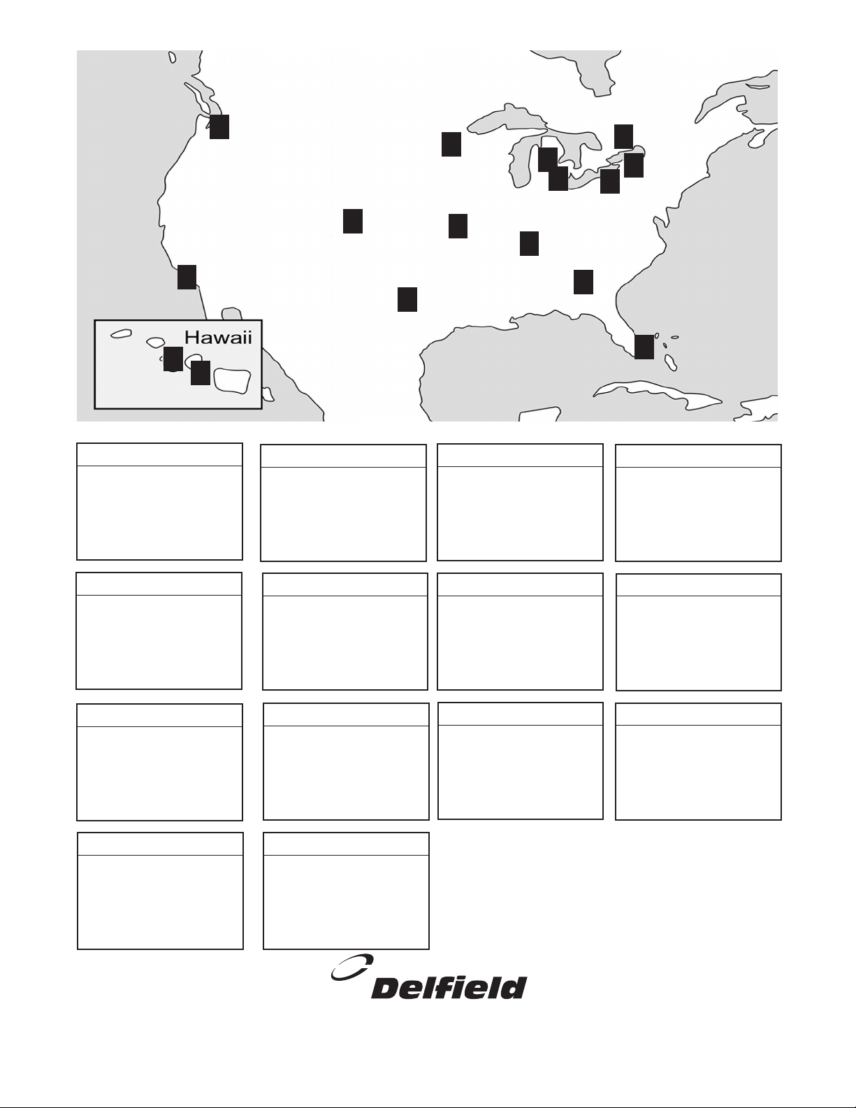
1336 Main Street
Buffalo, NY 14209
800.722.1252
716.884.7425
716. 884.0410 FAX
serves: CT, DC, DE, MA, MD, ME,
NH, NJ, NY, PA, RI, VA, VT, WV
3) Appliance Installation Ser vice
5367 2nd Street
Irwindale, CA 91706
800. 258.6999
626.960.9390
626.337.4541 FAX
serves: AZ, CA, HI, NV, OR
4) Barker's Food Machinery
2916 Sidco Drive
Nashville, TN 37204
615.726.0351
800.737.0351
615.259.4100 FAX
serves: TN, AL
14) T.M.A.
14450 Ewing Ave S. #100
Burnsville, MN 55306
800.422.2823
952.894.4427
952.894.2164 FAX
serves: IA, MN, MT, ND, SD, WI
5) Contract Ice
3909 St. Timothy Lane
St. Ann, MO 63074
800.972.7670
314.427.7477
314. 427.8190 FAX
serves: AR, IA, IL, KS,
KY, MO, NE, OK, TX, NM, LA
6) E.M.C.O. Sales & Distributors
2920 N.W. 109th Avenue
Miami, FL 33172
305 994.9994
305.994.9992 FAX
International parts depot
9) Global Parts and Supplies
10850 Sanden Drive
Dallas, TX 75238
1.800.442.5026 toll free
972.484.2954 local
214.340.2363 fax
serves: AR, LA, NM, OK, TX
7) GCS SERVICE
9923 S.W. 178th St.
Vashon, WA 98070
888.872.2465
206-463-1772
206.463.4431 FAX
serves: AK, HI, ID, MT, OR, WA
12) Performance Refrigeration Parts
2200 Norcross Parkway, Suite 210
Atlanta, GA 30071
800.235.6516
770.446.6177
770.446.3157 FAX
serves: FL, GA, MS, NC, SC, VA
13) Southeastern Restaurant Services
1816 West 26th Street
Erie, PA 16508-1149
800.332.3732
814.456.3732
814.452.4843 FAX
serves: MD, NJ, OH, PA, VA, WV
2) A.I.S. Commercial Parts & Service
1177 Kamato Road
Mississauga, Ontario L4W1X4
800.427.6668
800.361.7745 FAX
serves: Canada
8) Garland Group
980 South Isabella Road
Mt. Pleasant, MI 48858
800.733.8829
989.773.7981
989.773.3210 FAX
custom parts direct from Delfield
1) The Delfield Company
44792 Helm
Plymouth, MI 48170
888.828.4454
734.451.2043
734.451.3215 FAX
serves: MI, IN, WI, OH
11) MicroDine, Inc.
3000 S. Wyandot
Englewood, CO 80110
(800) 624-2117
(303) 7618861 FAX
serves: AZ, CO, KS, NE, NM, OK, UT, WY
10) Hawkins Commercial Appl. Ser v.
NORTH
AMERICA
4
4
12
9
10
1
11
7
6
5
14
3
13
8
2
Delfield has 14 conveniently located Parts Depots to ensure parts are handled promptly and accurately.
12
DM7/70/90 05/02
 Loading...