

Page 1
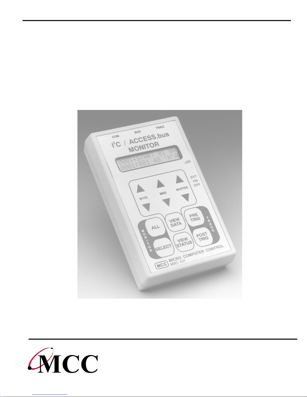
User’s Guide
I2C Bus / SMBus Monitor
and
2
C/SMBus Software Analyzer
I
Version 1.6
Micro Computer Control Corporation
www.mcc-us.com
Page 2

This user’s guide is for use with MCC’s I2C/SMB us Monitor
(#MIIC-101), and I
Table of Content s:
2
C/SMBus Analyzer Software (#SMB - SW)
System Requirements (Remote Mode Only)
System Components
Optional Add-On Parts
Introduction
2
I
C Bus / SMBus Monitor.................................. 1
.................................................. 1
............................................I
.........................................I
Product Features ......................................... 2
Input / Output Ports
2
I
C Bus / SMBus Port..................................... 3
........................................... 3
RS-232 Serial Port ....................................... 4
External Trigger Port ..................................... 4
Set-Up
...................................................... 5
.........................I
Connecting a Power Source ................................ 5
Internal Battery Power .................................... 5
External Power .......................................... 5
Connecting to an I
Connecting the External Trigger............................. 6
Connecting the Serial Cable (optional)........................ 6
Operating Modes
............................................. 9
Stand-Alone Operation .................................... 9
Quick Start ............................................. 9
Address Select Mode .................................... 10
View Status Mode....................................... 10
2
C Bus / SMBus........................... 6
Page 3

Trace Mode............................................ 11
View Data Mode........................................ 11
Remote Mode .......................................... 13
Bus Simulation Mode.................................... 13
Remote Operation....................................... 14
2
I
C Bus / SMBus Analyzer Software
Quick Start ............................................ 15
Software Installation ..................................... 16
Equipment Setup ....................................... 16
Starting The Program .................................... 16
Program Controls:....................................... 17
Button Controls: ........................................ 17
Check Box Controls:..................................... 18
Grid Control:........................................... 19
Menu Controls:......................................... 19
............................. 15
Application Program Interface
Command Syntax ....................................... 22
Baud Rate Select........................................ 23
ASCII Remote Select .................................... 24
Binary Remote Select .................................... 25
CTS/RTS Handshaking Command.......................... 27
Dump Trace Buffer...................................... 27
Enable Bus Simulation ................................... 28
Remote Trace .......................................... 29
Select Address.......................................... 29
Remote ............................................... 29
Test System............................................ 30
Help ................................................. 31
Appendix A - Solving Proble ms
................................. 22
................................. 32
Appendix B - Oper ating Specifications
Appendix C - Seri al Port Co mmands
........................... 34
............................ 34
Page 4

LIMITED WARRANTY
Micro Computer Control (MCC) Corporation warrants this products against
defects i n materials and workmanship for a peri od of ni nety (90) days from
the original date of purchase.
This limited warranty is not appl i cable to:
1) Normal wear and tear;
2) Abuse, unreas onabl e use, mistreatment or neglect;
3) Damage caused by the equipment or system with whic h t he product is
used; or
4) Damage caused by modifi cation or repair not aut hori zed by MCC.
THIS WARRANTY IS EXTENDED TO THE ORIGINAL PURCHASER
ONLY AND IS IN LIEU OF ALL OTHER WARRANTIES, INCLUDING
IMPLIED WARRANTIES OF MERCHANTABILITY AND FIT NE SS FOR
A PARTICULAR PURPOSE.
In no event will MCC be liable for any incidental or consequential damages.
During the warranty period, MCC will repair, replace or refund the purchase
price of any product found defecti ve at its opti on. Returned item s require
an RMA (Return Material Aut hori zation) issued by MCC, must be c aref u l l y
packaged, insured for the full repl acement value, with shipping charges
prepaid, before the return will be accept ed.
Page 5

I
System Requirements
(Remote Mode Only)
The I2C/SMBus Monitor can be used in stand-al one mode or host
2
comput er controlled remote mode. To use the I
2
remote mode with the I
C/SMBus A nal yzer Software, your PC m ust meet
the following requirements:
IBM PC or 100% compatible System.
4MB of RAM.
1 MB Free Hard Disk Space.
Microsoft Windows 3. 1, 3.11, 95, 98, NT or above.
Mouse.
VGA or Better Monitor.
1 Free RS-232 Serial Port (COM1, 2, 3,4).
C/SMBus Monitor in
System Components
The I2C/SMBus Monitor package includes the following com ponents:
2
1. I
2. I
3. I
4. RS-232 Serial Cable, 7Ft. with DB-25 adapter (#MEE-P S).
5. W al l Transformer (depending on power conf i gurat i on selected, see next
6. User’s Guide.
7. I
C/SMBus Monitor (#MI IC-101)
2
C Bus Clip Lead Cable, 2Ft. (#CABCL).
2
C Interface Cable, 4Ft. (#CAB 4).
pg).
2
C/SMBus A nal yzer S oftware (#SMB-SW) for rem ote usage, (incl uded
with MIIC-101K only)
Page 6
Power Configurations
Standard (#MIIC-101) 120 VAC 60Hz 6W to 5VDC
300mA Regulat ed, USA Plug.
European (#MIIC-101E) 220V~50Hz 5W to 5V 300m A
Regulated, European P l ug.
International (#MIIC-101I) 120 VAC 60Hz 6W to 5VDC
300mA Regulat ed, USA Plug,
220/240VAC, 50-60Hz, up to 50
W atts Converter, and I nternational
Adapter Set.
Optional Add-On Parts
1. I2C/SMBus Analyzer Software (#SMB-SW).
2
2. I
3. I
4. I
C Interface Cable, 8Ft. (#CAB 8).
2
C Interface Cabl e, 16Ft. (#CAB16).
2
C Bus Clip Lead Cable, 2Ft. (#CABCL).
Page 7
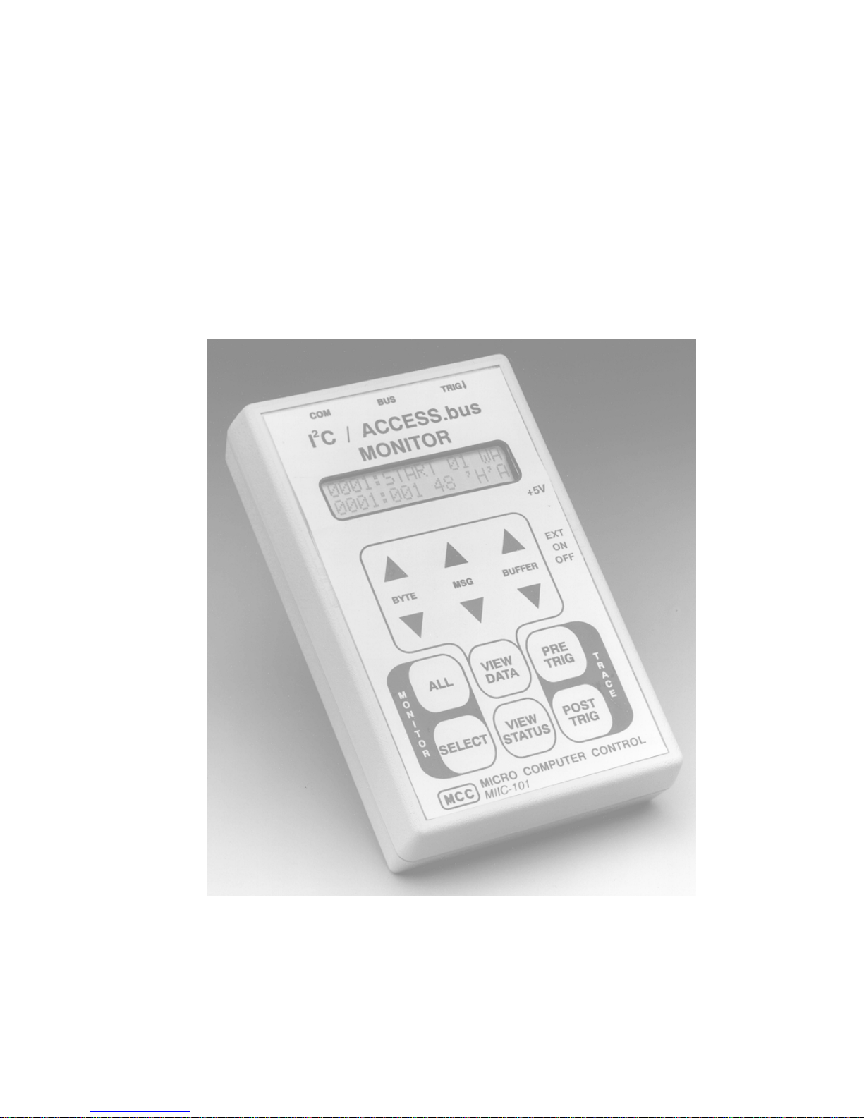
I2C Bus / SMBus
Monitor
Model No. MIIC-101
Page 8

Introduction
I2C Bus / SMBus Monitor
1
The
Integrated Circuit (
System Management Bus
connected to an I
2
I
C Bus / SMBus Monitor
2
) Bus developed by Philips Semiconductors and the
I
C
(SMBus
2
C Bus or SMBus network, the I2C Bus / SMBus Monitor
is a Troubleshoot i ng Tool f or the Inter-
) developed by Intel Corporat i on. W hen
can capture and display bus m essage activi ty.
2
The I
remote. In
capture and displ ay of bus mes sages. In
C Bus / SMBus Monitor can operate in t wo m odes, stand-alone and
stand-alone mode
, the built -i n di splay and keypad supports the
remote mode
, the moni tor is
controlled by a hos t comput er vi a an RS-232 serial communic ations port.
For remote mode operation, MCC offers an optional Windows-based
Bus / SMBus Analyzer
software (#SMB-SW) to provi de remote cont rol of
2
C
I
the monit or from a PC. This software allows bus message data t o be
captured, logged, filtered, displayed, and analyzed using one of several
built-in protocol parsers, i ncluding the dis pl ay of Smart Battery Syst em
(
SBS
) mess ages in engineering units .
In addition to MCC’s standard soft ware, a c ustomer may also develop
custom software to meet special processing requirements. Custom
software can cont rol , collect , and upl oad bus mess age data to a host
system. This provides a powerful tool for integrati ng the monitor into an
automatic manufacturing-test environment. Remote cont rol i s
accom pl i shed via a series of ASCII t ext commands . A description of the
monitor comm and set is provided in the Applicati on Program Interface
section of this m anual .
2
The complete I
C Bus / SMBus Monitor package c onsists of a hand-held
unit, connecting clip-l ead and i nterface cables, power supply, and optional
W i ndows-bas ed analyzer software.
Page 9
2
Product Features
I2C Bus and SMBus Compatible.
Captures bus t raf fic to 100kHz with minim al clock-s t retching
requirements.
Compatibl e with 3.3 to 5 volt bus logic.
Trace Buffer stores up to 2700 messages. Unl i mited when operated in
remote mode.
Stand-Alone and Remote Operating Modes.
RS-232 Port supports Host Computer communication.
Optional sof t ware integrates monitor and PC resources.
Page 10
Input / Output Ports
3
The
TRIG
2
I
CBus/SMBus Monitor
) for connect i ng t he uni t to the network under tes t and an optional
includes t hree I/O ports (
Bus, COM
, and
host computer syst em.
This section provides a general description of these I/O ports . For specific
port use, s ee t h “Installation” section of this guide.
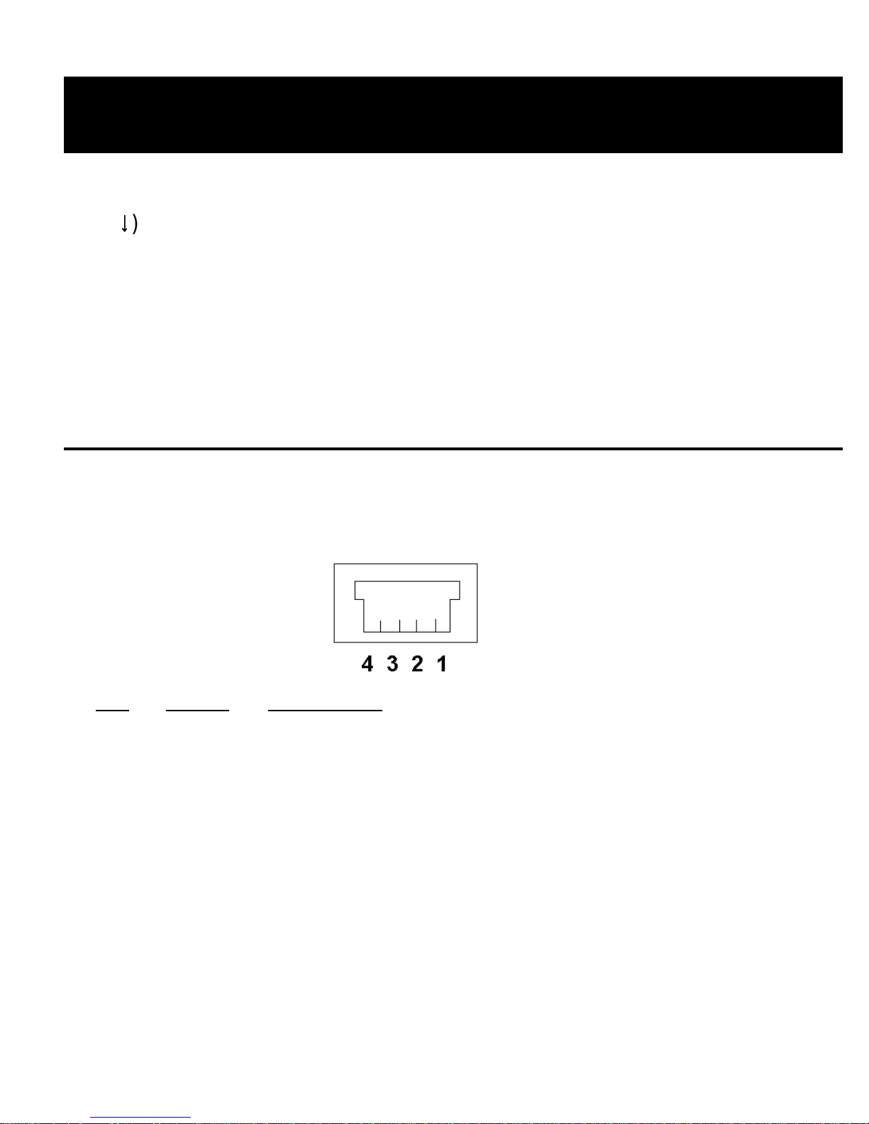
I2C Bus / SMBus Port
The monitor provi des a Molex Semicon connector (
2
the I
C Bus or SMBus.
BUS
) for connect i ng to
Pin
Signal Description
1 GND Ground Line
2 SDA Data Line
3 V Bus +5V (Optional )
4 SCL Clock Line
A clip lead cable (#CABCL), included with the unit, provi des connection to
the system under test . The Bus +5v line is used to optionally s uppl y or
source power from the target system. See the Power Supply Secti on f or
informat i on on the use of this line.
Page 11
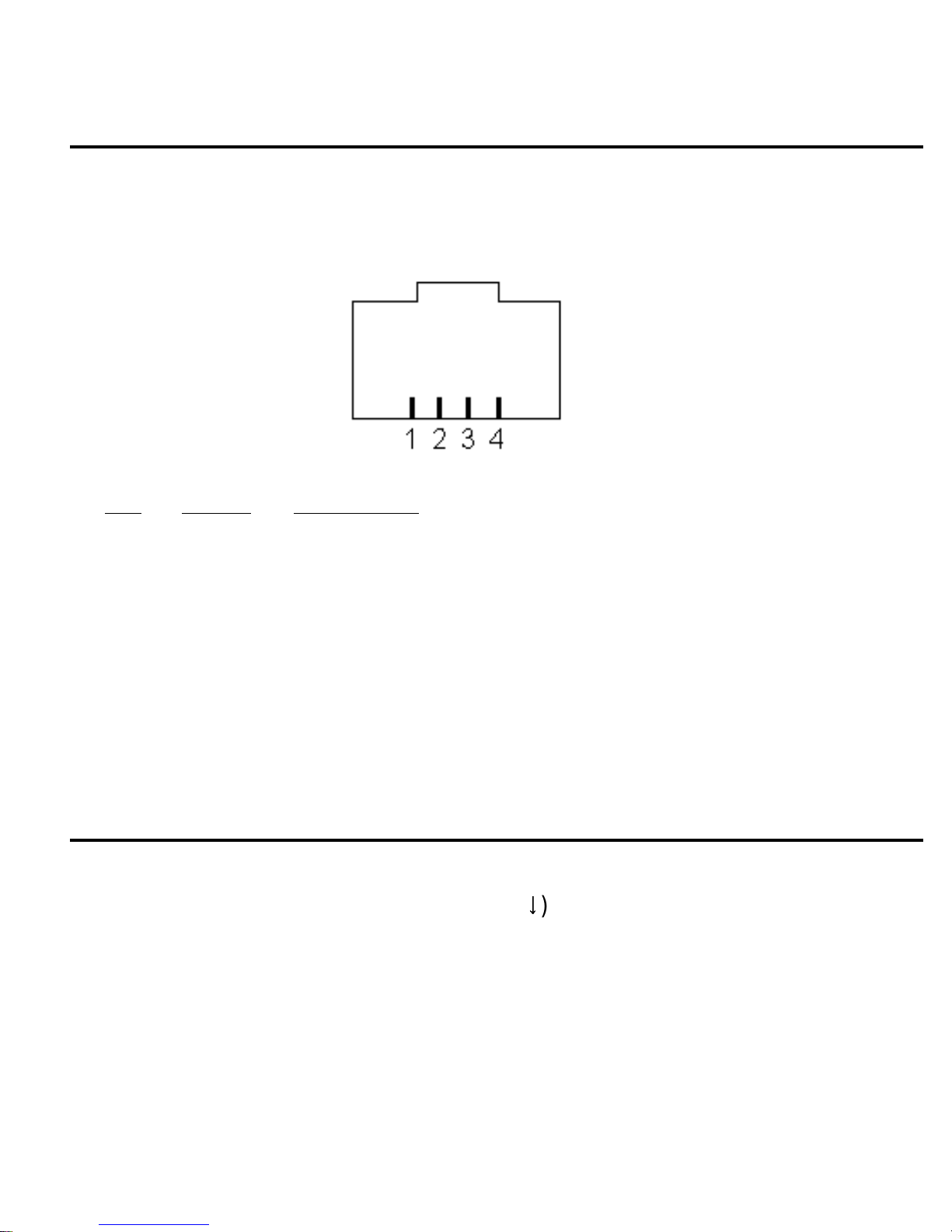
RS-232 Serial Port
4
An RS-232 serial port connector (
COM
) and cable provides c onnection to
an optional Host system. Thi s port provides remote unit control and data
uploading capabilities.
Pin
Signal Description
1 CTS Clear To Send (Host > Monitor) (Optional)
2 TX Data (Monitor > Host)
3 GND Ground Line
4 RX Data (Host > Monitor)
A serial port cable with DB-25 and DB-9 adapter, i n cluded with the unit,
provides connection to the RS-232 s e ri al comm uni cations port on an
optional Host system.
External Trigger Port
An External Trigger port connector (
TRIG
synchronization with external signals. The tri gger i s activated on a hi gh t o
low signal transit i on.
) and clip lead provides Trace
Page 12

5
Set-Up
Connecting a Power Source
The I2C Bus/SMBus Monitor can be powered from either internal or
external power sources.
Internal Battery Power
An internal 9V battery provides unit power when the power switch is i n the
position. Thi s power source allows the unit t o operate stand-alone, or
ON
when another power source is unavailable.
External Power
W hen the power switch is in the
EXT
ernal position, the unit can be
powered from:
1. The BUS +5V (V) Input line.
2. A regulated +5V wall power supply (Digi -Key #T309-ND or CUI/Stack #
DPR050030-P6) through the external power jack (
~ ~ ~ ~
CA UTION
~ ~ ~ ~
+5V
).
Powering the monit or from its +5V external power jack applies power to
the BUS +5V (V ) l i ne. The BUS V line shoul d onl y be connected to the
system under test if : a) You are powering the monit or from the target
system; or, b) You are powering the target system from the monitor.
NOT CONNECT BOTH THE WALL POWER AND TARGET POWER
SUPPLIES TOGETHER.
DO
Page 13

6
Connecting to an I2C Bus / SMBus
The unit provides a t est clip lead c abl e for connection to an I2C Bus or
SMBus under test. On the moni tor, the test clip cable connects t o t he
Molex Semicon modular connector marked
BUS
.
Test cli ps are provided for:
Clip ID
Signal Description
G GND Ground Line
2
DSDA I
C/SMBus Data Line
V V +5V (Optional)
2
CSCL I
C/SMBus Clock Line
For informat i on on using the +5v option, see the “Power Supply Sec tion”
of this gui de.
Connecting the External Trigger
The monitor provi des External Triggering for Trace s ynchronization with
external events. Trace synchronization allows bus traffic t o be collected
immediately before or af t er an el ectronic event.
A High-to-Low transit i on on t he External Trigger port can be used t o start
a PRE-TRIG trac e, or stop a POST-TRI G t race. See the Trace Mode
section of this guide fo r t race synchronizati on det ai l s.
Connecting the Serial Cable (optional)
The Serial Cable provides the connection bet ween the monitor and an
optional Host system. On monitor, the Serial Cable connec ts to the
modular RJ-45 connector m arker
connects to a standard RS-232 serial communicati ons port. Both DB -25
COM
. On the Host system, the cable
and DB-9 connect ors are supported.
Page 14
7
W hen using a Host computer, data terminal, or terminal emulator
program to ac cess the monitor via it s RS-232 port, c ommunication
parameters must be properly s et before communicati ng can begin.
The monitor operat es with the following Serial Li nk communication
parameters:
Baud Rate * 19.2K or 57.6K
Parity None
Data Bits 8
Stop Bit s 1 or 2
* The monitor def aul ts to 19.2K baud at power up. S ee t he Serial
Comm and section for more inform ation on switching t o baud rates.
The monitor’s serial port is configured as a Dat a Communications
Equipment (DCE) device, thus permitt i ng di rect connect i on to a PC’s
standard RS-232 serial communicati ons port. In thi s configurati on, onl y
three (3) wires (TX, RX, and GND) are required to establish serial
communication. An optional fourth handshaking wire may be used to
establis h hardware flow control.
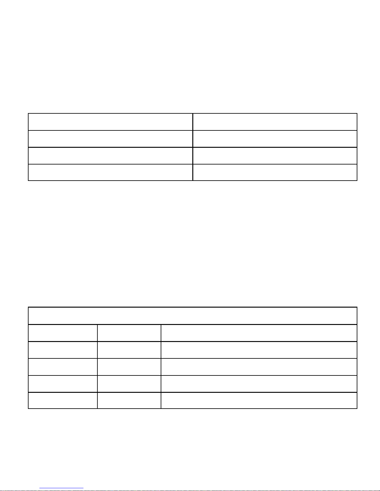
DB-25 Pin Assignments
Pin Name Description
2 TX Transmit Data to Monitor
3 RX Receive Data from Monitor
4 RTS Request to Send t o Monit or (Optional)
7 GND Signal Ground
Page 15
8
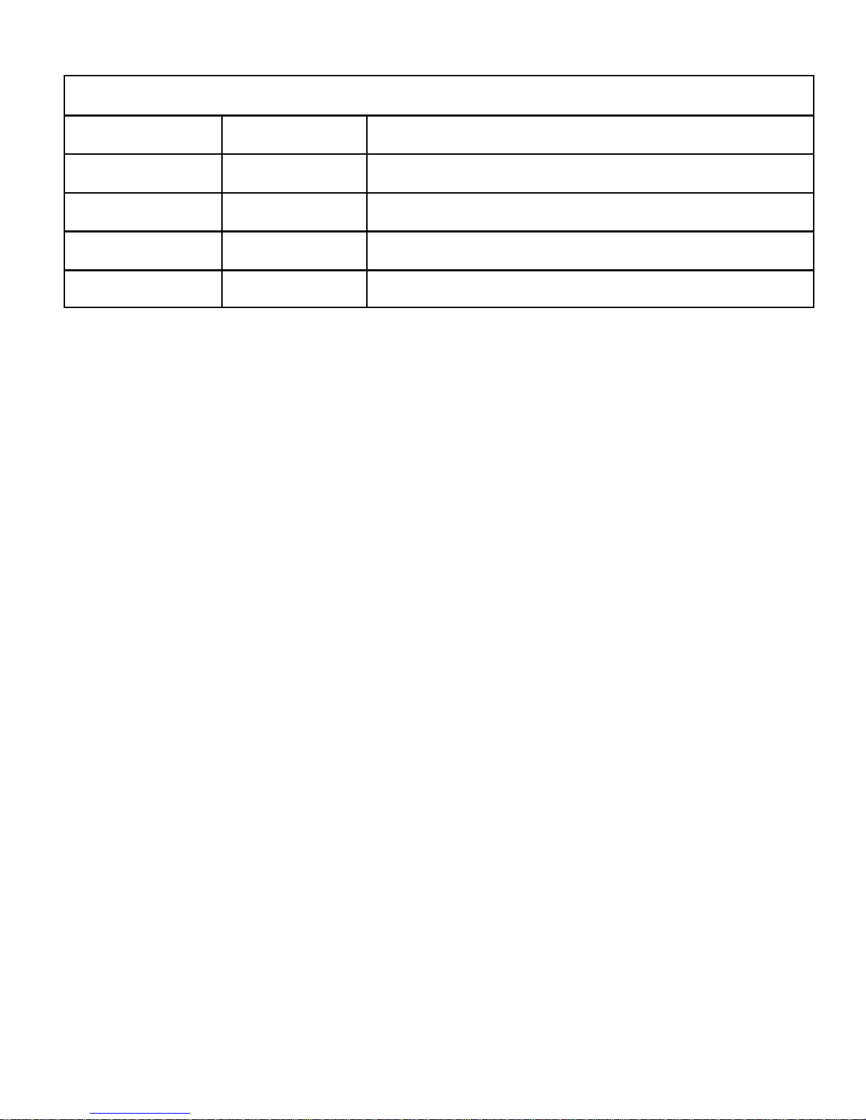
DB-9 Pin Assignments
Pin Name Description
2 RX Receive Data from Monitor
3 TX Transmit Data to Monitor
5 GND Signal Ground
7 RTS Request to Send t o Monit or (Optional)
Page 16
9
Operating Modes
The I2C Bus / SMBus Monitor can operate in t wo m odes, stand-alone
and remote. In
supports t he capture and display of bus data. In
stand-alone mode
, the built -i n di splay and keypad
remote mode
monitor i s controlled by a host com put er vi a an RS-232 serial
communications port.
Stand-Alone Operation
Quick Start
1. Connect monit or to the target bus.
2. Turn monitor power to
3. Select address mode
4. Press
PRE
or
POST-TRIG
PRE-TRIG waits for TRIG
5. Press
VIEW-DATA
button to end capture and enable
ON
ALL
or
EXT
or
SELECT
.
.
Trace button to begi n data capture.
line low or repeat PRE-TRIG but ton press.
BYTE, MSG
, the
,
and
W hen using the I
BUFFER
display scroll buttons .
2
C Bus/SMBus Monitor stand-alone, the unit performs
data collec tion and display usi ng ei ght (8) operating modes. These modes
include:
Operation Description
Address Sel e ction Select slave address to monitor
View Status View bus signal logi c levels
Trace Capture bus message data
View Data View captured bus data
Remote Capture/Transmit bus data
Simulation Simulate bus message data
Page 17

10
Address Select Mode
Address Sel ect Mode is used t o select the bus slave address or
addresses the unit will monit or.
Address Sel ect Mode is entered by pres sing the
MONITOR-ALL
key on the unit’s front panel.
MONITOR-SELECT
or
The MONITOR-SELECT key i s used to spec i fy a single bus s l ave
address to m onitor. The first ti me this key is pres sed, the unit will display
the current selected slave address. Subsequent key pres ses will step the
unit through all possible slave addresses.
Pressing the MONITOR-ALL key instructs t he uni t to collect bus traffi c to
all slave addres ses.
Pressing any other mode select key terminates Address Selec t Mode with
the displayed addres s selected.
Slave address selection may also be set with the Select Address Seri al
command. For more i nf ormation see the Serial Command sect i on i n this
guide.
View Status Mode
View Status Mode displays bus and TRIG l i ne l evels.
View Status Mode is entered by pressing the
VIEW-STATUS
unit’s front panel .
In View Status Mode, the unit dis pl ays the following line l evel s (“0" for <
0.5V, “1" for > 2.5V):
A.bV - Bus +5V Line
SCL - Clock
SDA - Data
TRIG - T race Trigger Input
key on the
Page 18

11
Selecti ng any ot her operating mode terminates V i ew St at us Mode.
Trace Mode
In Trace Mode, the unit collects and stores all or s el ected bus traff i c with
PRE or POST Trace triggering.
Trace Mode is entered by pressing the
PRE-TRIG
or
POST-TRIG
key on
the unit’s front panel. All previ ously collect ed data is erased from the
monitor’s internal st orage. Bus traffic to one or all slave devices i s
collect ed i n accordance with the c urrent Address Sel ect Mode defined
above.
Pressing t he PRE-TRIG key instructs the unit to st art collect i ng bus traffic
upon receiving a trigger s i gnal . Pressing the PRE-TRIG key agai n, or a
High-to Low transition on the External Trigger line will trigger data
collect i on. Once started, PRE-TRIG data col l ection continues until the
monitor’s internal trace buffer is ful l , or another operating m ode i s
selected.
Pressing t he POST-TRIG key i nstructs the unit to start collec t i ng bus
traffic i mmediately. Once st arted, POST-TRI G data collect i on continues
until a High-to-Low transi tion is detec ted on the External Trigger line, or
another operating m ode i s selected. Once the trace buffer is full , POSTTRIG tracing continues col l ecting data by overwriting the ol dest stored
data with the newest.
Selecting any other operating mode terminates Trace Mode.
View Data Mode
View Data Mode displays dat a captured during the las t trace of bus
activit y. Displayed inf ormation inc l udes:
• Number of Messages : Bytes Captured
• S tart/Stop E vent s
• Message Number and Message B yt e Number
• Message Destinati on Slave Address
• Read/ Write Requests
Page 19

12
• A cknowledgments and Negat ive-Acknowledgment s
• Trans mitted Dat a i n Hex and ASCII
• V i ew Data supports forward and reverse scrolling of captured data
bytes or m essages.
View Data key/ac tions incl ude:
Key
BYTE-UP
BYTE-DOWN
MSG-UP
MSG-DOWN
BUFFER-UP
BUFFER-DOWN
Action
- Move Backward one byte.
- Move forward one byte.
- Move Backward one mes sage.
- Move Forward one message.
- Move to Start of buffer.
- Move to End of buffer.
The monitor uses the foll owing dis pl ay syntax:
2
C Event Display
I
Start of Buffer [- START OF TRACE -]
.
Start Read w/Ack [MMMM:ST ART AA RA ]
Data w/Ac k [MMMM:NNN DD
Stop Condit ion [ MMMM:STOP ]
.
End of Buffer [ -- END OF TRACE -- ]
where:
MMMM - Trace Message Number
NNN - Message Byte Number
AA - Device Addres s
DD - Data in Hexadecimal Format
C - Data in ASCII Format
R/W - Read or W ri te Request
N/A - Receiver Non/Ac knowledgment
C
A]
Page 20

13
Selecti ng any ot her operating mode terminates V i ew Data Mode.
Remote Mode
In Remot e Mode, the unit is c ontrolled by a Host c omputer system via it s
serial port. B us traffic can be collect ed or upl oaded to the Host s ys tem for
storage and furt her anal ysis.
Remote Mode is entered when the unit receives a
Serial Command
at its
serial port.
The monitor responds to a variety of Serial Com mands incl udi ng:
• B aud Rate Select
• A SCII or Binary Remote Upload Sele ct
• S l ave Address Select
• Dump Trace Buff er
• Remote Trace
• Help
For more information see t he A pplication Program Interface section i n t hi s
guide.
Selecti ng any ot her operation mode terminates Remote Mode.
Bus Simulation Mode
In Bus Si mulation Mode, t he monitor simulates I
bus connect i on. Emulat i on provi des a learning and test i ng pl at form
without the need for a working bus.
Bus simulation is enabled by pressing t he
front panel during the power-up sequenc e. Once enabled, bus simulati on
remains i n effect unti l the next unit power-up cycle.
2
C Bus traffic without a
BUFFER-UP
key on the unit’s
Page 21

14
During Trace operations , bus simulation repetit i vel y generates the
following three bus messages:
10234836536C36C36F500 - Start 02, W, A, “Hello”, Stop
10435736F37236C364500 - Start 04, W, A, “World”, Stop
2FF500 - Start FE, R, N, Stop
See ASCII Remote Select Serial command f or details on ASCII format.
Bus simulation can al so be enabled with the Bus S i mulation Enabl e Serial
command. For more i nf ormation see the Serial Command sect i on i n this
guide.
Remote Operation
remote mode
In
RS-232 serial c ommunications port. In this mode, bus traffic can be
collect ed or upl oaded to the Host s ys tem for s torage and further analysis.
For remote mode operations, MCC of f ers Windows-based
SMBus Analyzer
software, desc ri bed bel ow, c an be purchased with the m oni t or i n kit form
(#MIIC-101K), or the software can be separatel y purchased (#SMB-SW).
A cust omer may also develop custom soft ware to meet speci al
processing requi rements. Remote cont rol i s accom pl i shed via a series of
ASCII t ext commands . A descript i on of the monit or comm and set is
provided in Appendix C.
, the m oni t or is controll ed by a host com puter via an
2
C Bus /
I
software to provide remote control of the monit or. This
Page 22
15
I2C Bus / SMBus Analyzer Software
Quick Start
1. Instal l analyzer software.
2. Connect monitor to the t arget bus.
3. Connect monitor to host PC COM port.
4. Turn monit or power to
5. Select
COM
port connect ed t o bus monitor.
ON
or
EXT
.
6. Select bus slave addresses to monitor.
7. Click
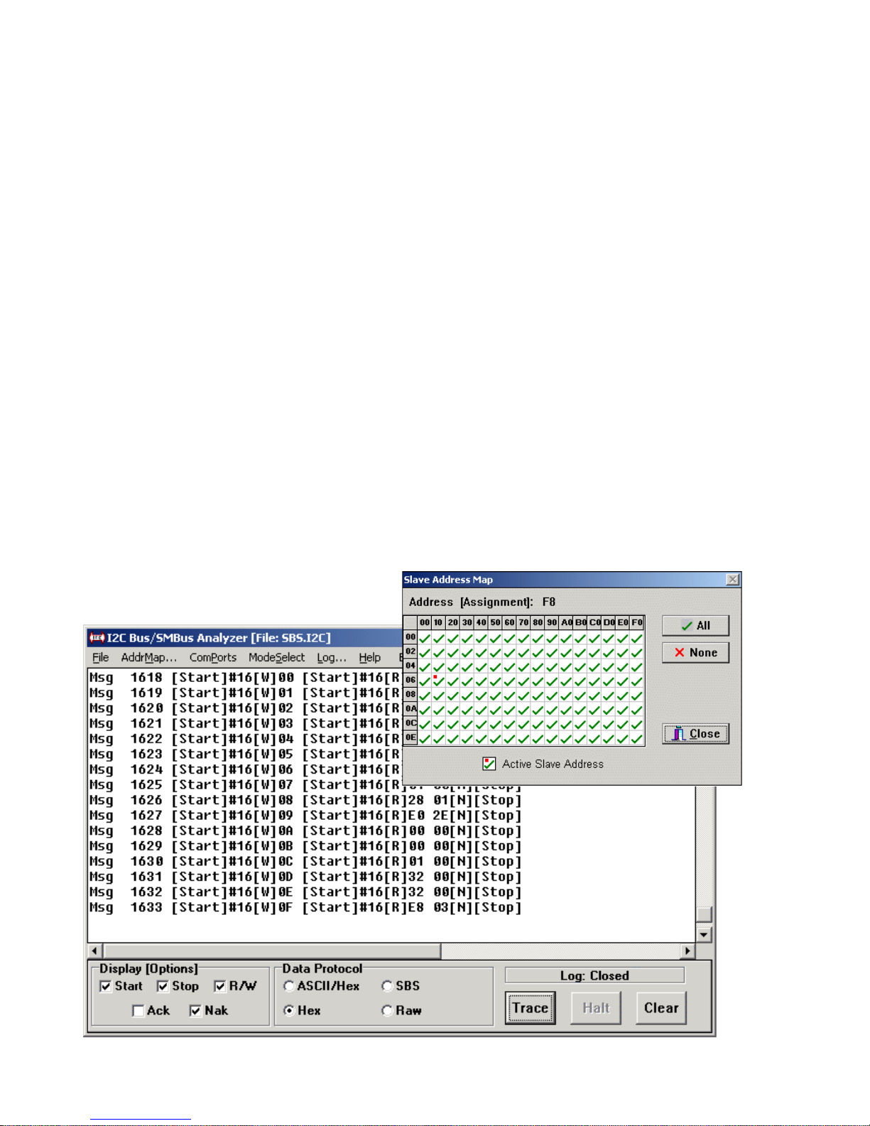
The I
Trace
2
C/SMBus Analyzer Software provides real-t i me capture and onscreen disp l ay of live or previously recorded I
is designed t o work with t he I
button.
2
C or SMBus m essages. I t
2
C Bus / SMBus Monitor (#MIIC-101). The
software also provides filtering of displayed messages by device slave
address, and provides a global display of bus activity over all 7-bit s l ave
addresses.
Page 23

16
Software Installation
For W i ndows 95 and above:
1. Insert software distribution disket te into floppy drive.
2. Select Start|Run. Type "a:setup".
3. Follow instructions on screen.
For W i ndows 3. x or NT 3.51:
1. Insert software distribution disket te into floppy drive.
2. Select Fi l e|Run. Type "a:setup".
3. Follow instructions on screen.
Equipment Setup
1. Connect monitor to a PC COM port - COM:1, 2, 3 or 4.
2
2. Connect monitor to the target I
C Bus using the clip lead cabl e.
3. Turn monit or power ON.
NOTE
: Previousl y c o l l ected raw (*.i2c) fil es may be analyzed off-line.
Several such file are automatically ins talled during product i nstallation.
See the File|Load feature below.
Starting The Program
For W i ndows 95 and above:
1. From Start Menu, select Programs |I 2C Bus_SMBus Analyzer.
2. Click on I2C Bus_SMBus Analyzer.
For W i ndows 3. x or NT 3.51:
Page 24
17
1. From Program Manager double click on the I2C Bus _S MBus Analyzer
Program Group.
2. Double click on I2C Bus _SMBus Analyzer Program Item.
2
The I
C/SMBus A nal yzer Software can displa y real -time or previous l y
recorded bus data. To di splay live data, s el ect the COM port connec t ed to
the Bus Monitor, then click on the Trace Button. To display previousl y
recorded log file data, clic k File|Load and select a raw I2C (*.i2c) log fil e.
Several sample log files are automatic al ly installed in the software default
folder (sub-direc tory) during software installation.
Program Controls:
I2C/SMBus Anal yzer Software program controls consi sts of ons creen
buttons, check boxes, grid c ont rol s, menu it ems, and dial og boxes. Thi s
section describes these controls and explains how to us e these controls
to capture and display bus message data.
Button Controls:
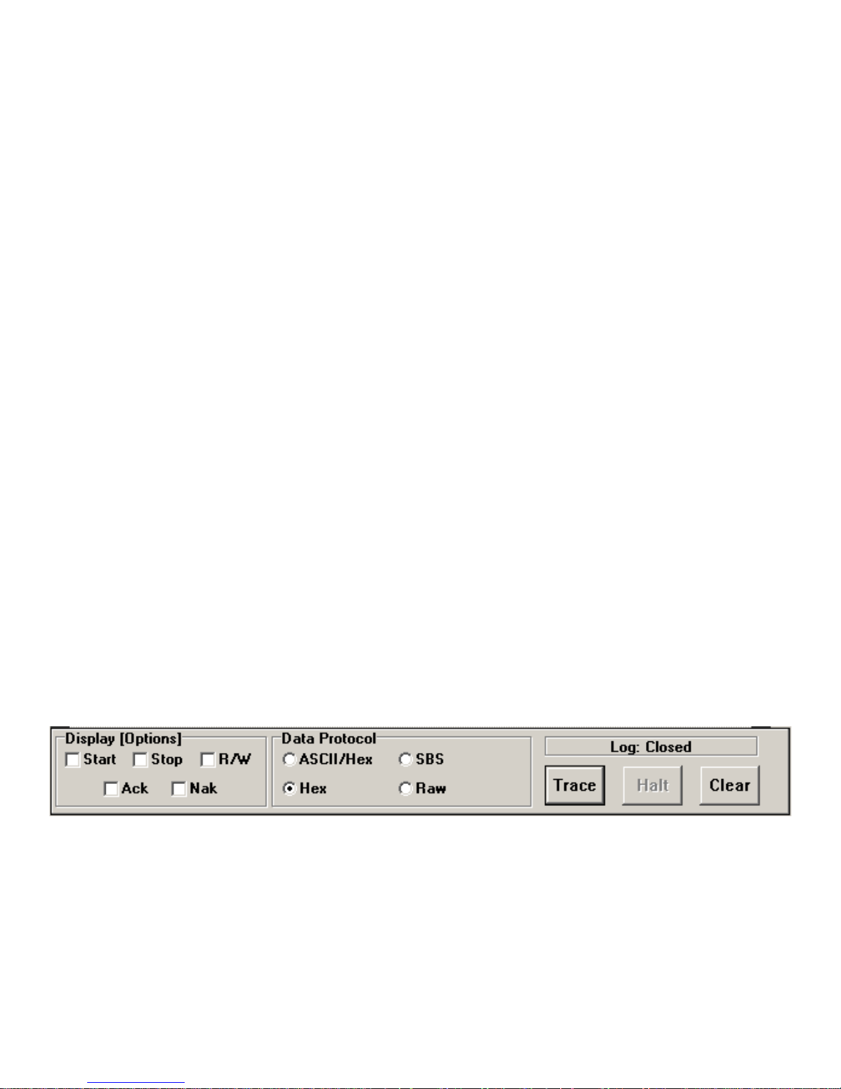
Trace
- This button i s available when the ModeSelect|Remote Trace
menu item is sel ected. Clic king this button puts the monitor into remote
trace mode, and will display real time data captured from the bus.
Message data is di splayed according t o the current slave addresses,
display options, and data protoc ol selected.
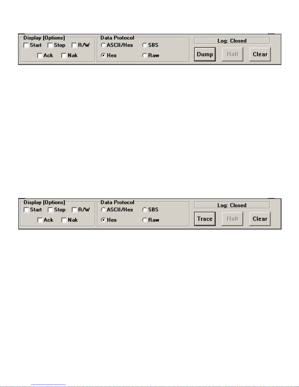
Dump
- This button i s available when the ModeSelect|Dump Buffer menu
item i s selected. Cl i cking this button puts t he monitor int o dump mode,
and will display previously recorded data captured from the bus that is
held in the m oni t or’s internal buff er. Message data is di splayed according
to the current slave addresses , display options, and data protocol
selected.
Page 25
18
More
- This button i s available when the File|Load menu i tem is selected,
and mess age di splay area is ful l . Clicki ng t h i s button reads and displays
additional previous l y recorded log file data. Mes sage data is dis pl ayed
according to the current slave addresses, di splay options, and dat a
protocol sel ected.
Halt
Clear
- Stop the dis p l ay of data.
- Clear the displ ay area.
Check Box Controls:
Display [Options]
- Display Control
These check boxes c ontrol the display of Start, S top, Ack, Nak and R/W
2
events within an I
Data Protocol
C or SMBus m essage.
- Select Data Display Protocol
ASCII/Hex Printable ASCII or Hexadec imal
Hex Hexadecimal
SBS System Management Bus
Raw Raw data received from monitor
Grid Control:
Page 26
19
AddrMap Grid
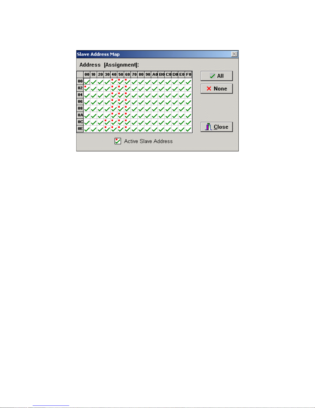
- Select Slave Addresses to Display
Select slave addresses t o display and moni tor address traf fic. Click on
grid cells to Enable (checked) or Disabled (x) slave address for display.
Enabled addresses show bus message activit y with a red dot . Selecti ng
a grid cell cl ears traffic indicator.
Menu Controls:
File|Load
- Load a File
Load a previously st ored f i l e for processi ng or di splay. The soft ware can
read/process /display log fi l es (*.i2c) previous ly collected from the monitor,
or can read/displ ay any ASCII text (*.txt) file. Message data is displayed
according to the current slave addresses, di splay options, and dat a
protocol sel ected. ASCI I text files are simply dis played.
File|Save As
- Save Data to File
Save the currentl y di splayed data to a fi l e. Up to 32K characters currently
displayed can be saved in a log file (*. i 2c) or ASCII t ext (*.txt) file. Saved
files c an be redi splayed using the Fil e|Load menu item.
File|Print Setup
- Setup printer.
Page 27

20
File|Print
- Print Displayed Data
Print the c u rrent l y di splay data. Up to 32K characters currently displayed
are printed.
File|Font Select
File|Save Setup
- Select di splay font and s i ze.
- Save Setup Parameters
The following program parameters are saved t o the file I2C.INI. These
parameters are aut omatical l y l oaded t he next ti me the program i s started.
ComPort Number
Display Opti ons
Protocol S el ection
Font Selection
Hints On/Off Selection
AddrMap
- Display Address Map Grid
See the AddrMap control definition above.
ComPorts
- Select Com Port
Select monitor connec ted com port and baud rat e.
NOTE
: The monit or defaults to 19200 baud at power up. Fas t er baud
rates can c ause loss of dat a on some PCs .
ModeSelect| Rem ote Trace
- Select Monitor Remote Mode
Bus m essages capt ured by the monitor are upl oaded for display.
ModeSelect|Dump Buffer
- Select Monit or Dump Mode
Previously captured bus mes sages held in the monitor’s internal buffer
are uploaded for displayed.
Page 28
21
ModeSelect| Message Display
- Select Message Mode
Bus messages are dis pl ayed upon receiving STOP at end of
mess age. This is t he default mode and provides fast display of message
data.
ModeSelect| Byte Display
- Select Byte Mode
Bus m essages are displ ayed upon receiving each byte of message dat a.
This mode can display partial or i ncomplete message dat a when a
complete mess age i s not being transmitted (i. e. missing STOP).
ModeSelect|Show Hints
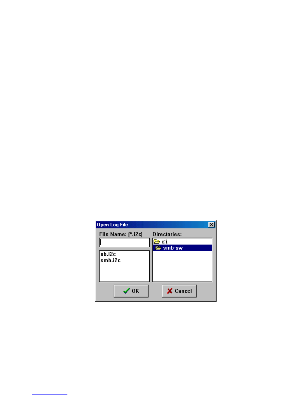
Log
- Log File Control
- Enables Program Controls hi nt di splay.
Open/close l og file (*.i2c) of data received from monitor. Log f i l es can
later be read/processed with the File|Open menu item.
Help|ReadMe
- Display technical notes
Help|Revision Report
Help|About -
Display so f tware informati on
- Display revision report
This section is a description for programmers writing custom applications.
Page 29

22
Appl ication Program Interface
The Host System Interface provides RS-232 port access to monitor data capture
functions. The monitor provides the following Serial Commands to assist in bus
traffic collection:
19.2K Baud Select . . . . . . . . . . . 1
57.6K Baud Select . . . . . . . . . . . 5
ASCII Remote Select . . . . . . . . .A
Binary Remote Select . . . . . . . . .B
CTS/RTS Handshaking . . . . . . . C
Dump Trace Buffer . . . . . . . . . . D
Enable Bus Simulation . . . . . . . .E
Remote Trace . . . . . . . . . . . . . . .R
Select Address . . . . . . . . . . . . . . S(ALL| [Slave Address] )
Test System . . . . . . . . . . . . . . . . T
Escape . . . . . . . . . . . . . . . . . . . . <Esc>
Screen Pause . . . . . . . . . . . . . . . <Ctrl - S>
Screen Resume . . . . . . . . . . . . . <Ctrl -Q>
?Help . . . . . . . . . . . . . . . . . . . . . ?
The following sections give details on the syntax and operation of these
commands.
Command Syntax
Serial commands consist of a single character command key possibly followed by
command parameters and terminated with the <Enter> key.
( ) Optional parameters.
[ ] Numeric parameters. All such parameters are specified in hexadecimal
without
a radix specifier. Example OO to FF.
| Alternate selection. Only one of the alternate selections is permitted.
Page 30

< > Control keys.
Baud Rate Select
23
Syntax:
1 (9200) | 5(7600)
Description:
The Baud Rate Select command sets the units serial port to 19.2K or 57.6K baud.
The unit defaults to 19.2K baud at power-up.
Executing a Remote Trace on high volumes of bus traffic at 19.2K baud may
cause loss of data on buffer overflows. Buffer overflows are marked in t he data
stream with the “???” string.
When executing a Remote Trace at 57.6K baud, the HOST system may lose data
on character overwrites. Character overwrite detection is a function of your
terminal emulation program.
Note
Immediately aft er i ssuing a Baud Rate Select command, the Host
system serial port must als o change to the matching baud rate.
Example:
5 <Enter> - 57.6K baud selected.
1 <Enter> - 19.2K baud selected.
Page 31

ASCII Remote Select
24
Syntax:
A
Description:
The ASCII Remote Select command configures Remote Trace data to be sent to
the serial port in printable ASCII format. At power-up, ASCII Remote is the
default transfer mode.
When ASCII Remote in enabled, data is transferred in three-character ASCII sets.
The first character specifies the data type, and is followed by a two character
slave address or data.
When executing a Remote Trace, data is sent to the serial port in the following
ASCII format :
TAATHH ...THH<CR><LF>
where:
T - Type
1 - Start with Acknowledgment.
2 - Start without Acknowledgment.
3 - Data with Acknowledgment.
4 - Data without Acknowledgment.
5 - Stop
AA - 8-bit Slave Address (00...FFH).
HH - 8-bit Data (00...FFH).
Example:
A<Enter>
R<Enter>
150320...323500<CR><LF>
where:
Page 32

25
1 - Start with Acknowledgment.
50 - Slave Address 50H.
3 - Data with Acknowledgment.
20 - Data 20H.
.
.
.
3 - Data with Acknowledgment.
23 - Data 23H.
5-Stop.
00 - Always 00.
In the above example, a single bus message is uploaded to the Host system in
ASCII format during a Remote Trace.
Binary Remote Select
Syntax:
Description:
The Binary Remote Select command configures Remote Trace data to be sent to
the serial port in Binary format.
When Binary Remote is enabled, data is transferred in two-byte binary sets. The
first byte specifies the data type, and is followed by a slave address or data byte.
When executing a Remote Trace, data is sent to the serial port in the following
Binary format:
B
TATH...TH<CR><LF>
where:
T- Type
Page 33
1 - Start with Acknowledgment
2 - Start without Acknowledgment.
3 - Data with Acknowledgment.
4 - Data without Acknowledgment.
5 - Stop.
A - 8-bit Slave Address (00...FFH).
H - 8-bit Data (00...FFH).
The Binary format is reserved for future MCC product s upport.
26
NOTE
Example:
B<ENTER>
R<ENTER>
150320...323500<CR><LF>
where:
1 - Start with Acknowledgment.
50 - Slave Address 50H.
3 - Data with Acknowledgment.
20 - Data 20H.
.
.
.
3 - Data with Acknowledgment.
23 - Data 23H.
5-Stop.
00 - Always 00.
In the above example, a single bus message is uploaded to the Host system in
binary format during a Remote Trace.
Page 34

CTS/ RTS Handshaking C o mmand
27
Syntax:
C
Description:
The CTS/RTS C ommand is used to toggle Clear-to-Send / Request-to-Send
Serial Link flow control. The power-up default condition is CTS/RTS
Handshaking disabled.
When enabled, CTS/RTS Handshaking halts monitor serial port output wh en the
Host RTS line is dis-asserted. This feature is useful in preventing serial link data
overflow on the host system .
The monitor always supports X-ON/X-OFF Serial link flow control. Sending an
X-OFF (Ctrl/S) character to the unit halts serial port output. Sending a
subsequent X-ON (Ctrl/Q) character causes output to continue. This feature is
useful during a Dump or Remote Trace to temporarily stop data scrolling.
Example:
C<Enter> - CTS/RTS Handshaking Enabled
Dump Trace Buffer
Syntax:
Description:
The Dump Trace Buffer command sends all bus data collected during the last
PRE-TRIG or POST-TRIG Trace to the serial port. Buffered data is u naltered by
this operation.
Data is sent to the serial port in ASCII format. See the ASCII Remote Select
command for format details.
D
Page 35

28
Dump Trace Buffer terminates upon exhausting the buffer, or upon receiving an
Escape <ESC> character on the serial port.
Screen Pause <Ctrl-S> and Screen Resume <Ctrl-Q> are active.
Example:
D<Enter>
In the above example, buffered bus messages are uploaded to the Host system in
ASCII format during a Dump Trace Buffer operation. See the ASCII Remot e
Select command for format detai ls.
Enable Bus Simulation
Syntax:
Description:
The Enable Bus Simulation command causes the unit to emulate bus traffic
without a bus connection. Emulation provides a learning and testing platform
E
without the need for a working bus.
Bus simulation repetitively generates the following three messages:
10234836536C36C36F500 - Start #2, “Hello”, Stop
10435736F37236C364500 - Start #4, “World”,
2FF500 - Start #FFH, Stop
Stop
See ASCII Remote Select for details on ASCII format.
Once enabled, bus simulation remains in effect until the next unit power-up
cycle.
Bus simulation can also be enabled by pressing the BUFFER-UP key during the
unit power-up sequence.
Page 36

29
Example:
E<Enter> - Enable Simulation
Remote Trace
Syntax:
Description:
The Remote Trace command places the unit in POST-TRIG Trace Mode, and
sends all bus traffic to the serial port.
During a Remote Trace, data in temporarily buffered in the unit, then sent to the
serial port in the currently selected ASCII or Binary format. See the ASCII
Remote Select or Binary Remote Select commands for data format details.
R
Remote Trace terminates upon receiving a High-to-Low transition on the
External Trigger line or an Escape <Esc> character on the serial port.
Screen Pause <Ctrl-S> and Screen Resume <Ctrl-Q> are active.
Example:
R<Enter> - Start Remote Trace
In the above example, bus messages are buffered and uploaded to the Host
system in the selected ASCII or Binary for mat. See the ASCII Remote Select or
Select Address
Binary Remote Select comma nds for data format details.
Syntax:
S(ALL | [Slave Address] )
Page 37

30
Description:
The Select Address command is used to select the bus slave address or addresses
the unit will monitor. During a PRE-TRIG, POST-TRIG, or Remote Trace, the
unit will capture all messages sent to this address.
Entering parameter ALL instructs the unit to collect bus traffic to all slave
addresses.
Entering a slave address parameter specifies a single bus address to monitor.
Slave address selection may also be set with the MONITOR-SELECT or
MONITOR-ALL keys. For more information see the “Introduction” section in
this guide.
Example:
SALL<Enter> - Monitor ALL Sl ave addr esses.
S50<Enter> - Monitor slave address 50H.
Test System
Syntax:
Description:
The Test System command invokes manufacturing test functions. This command
is reserved for MCC use only.
T
The Test Syst em com mand is reserved for MCC manufact uri ng and
support use only.
NOTE
Page 38

Help
31
Syntax:
?
Description:
The Help command displays the syntax for
Example:
?<Enter> - display monitor Help Screen
Monitor
command set.
Page 39

32
Appendix A - Solving Problems
Solving Problems
If you suspect a malfunctioning unit follow the steps described below before
contacting MCC for additional assistance.
Problem:
Unit does not display the sign-on message on the internal LCD display at
Power-up.
Solution:
1. Check the unit power supply. If the power switch is in the ON position, the
unit is powered by the internal 9V battery. Check and replace a faulty battery.
2. If the switch is in the EXTern al position, the unit can be powered by 5V
ACCESS.bus power, the Test Cable A.bV external power lead, or an external
5V wall transformer. Check and replace any faulty power source.
Problem:
Unit does not display the sign-on message on the Serial Link at Power-up.
Solution:
1. Check the Serial Link at unit and Host system.
2. Confirm that the unit and Host system are communicating at the same baud
rate and with the proper communication parameters.
Page 40

33
Problem:
Unit does not collect bus traffic in Trace Mode.
Solution:
1. Check cable connections at the unit and bus. When using the Test Cable,
confirm SCL, SDA, and GND clip leads are connected to appropriate bus
lines.
2. Check Selected Address. If a single bus address is specified, only messages
directed to that address will be collected. Confirm presence of bus traffic by
monitoring all bus addresses.
3. When using the External Trigger Port, the unit will wait for a trigger event.
Check the TRIG input using Line Status Mode. A High-to Low transition,
with minimum 2usec Low duration, is required to generate a trigger
condition.
Page 41

34
Appendix B - Operating Speci f ications
Operating Specifications
Parameter Min Typ Max Unit
Temperature Range
Operating Temperature 0 +50
C
Storage Temperature -25 +70
C
D.C. Characteristics
External Power -5% 5 +5% V
Input Current 20 40 mA
Internal Battery 9 V
SDA and SCL (I
2
C Signals)
Input Low Voltage -.05 +1.5 V
Input Hi gh Voltage +3.5 -5.5 V
Input Leakage Current +-20 uA
Input Capacitance
w/o Test Cable 20 pF
with Test Cable 60 pF
Trigger Input
Input Low Voltage -0.5 +0.9 V
Input Hi gh Voltage +1.9 +5.5 V
Input Current 100 uA
Input Capacitance 20 60 pF
Page 42

35
Appendix C - Serial Port Commands
Serial Port Commands
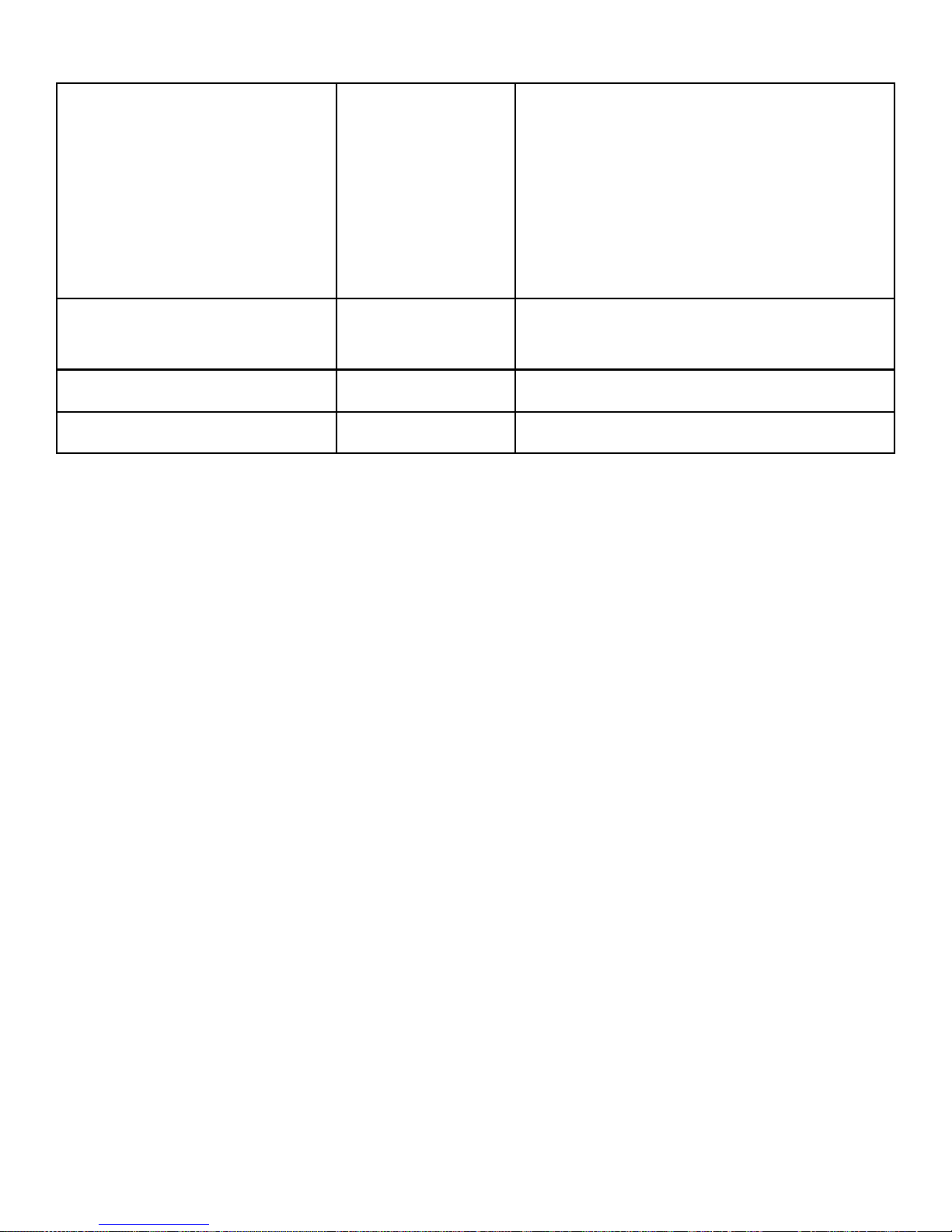
Command Syntax Description
Baud Rate Select 1<CR>
5<CR>
ASCII P rot ocol
A<CR> Configure Rem ote Trace to
Select
Binary Protoc ol
B<CR> Configure Rem ote Trace to
Select
CTS/RTS F l ow
C<CR> Toggle Clear To Send (CTS) /
Control
19.2K baud selec t
57.6K baud selec t
send trace data i n ASCII
format.
send trace data i n bi nary
format.
Request To Send (RTS)
RS-232 port flow control .
Dump Trace B uf fer D<CR> Dump pre-recorded message
Enable Simulation E<CR> Simulate bus mess age traffic
trace data in A S CII format.
without a bus connec t i on.
Page 43
36
Remote Trac e R<CR> Place monitor in POS T -TRIG
trace mode and sends all
captured bus t raf fic to the
serial port in the current
selected format (ASCII or
Binary).
Slave Address Select SALL<CR>
Sxx<CR>
Monitor all
Monitor single s l ave address
System Test T<CR> Enter test mode
?Help ?<CR> Display monit or help
 Loading...