

Page 1
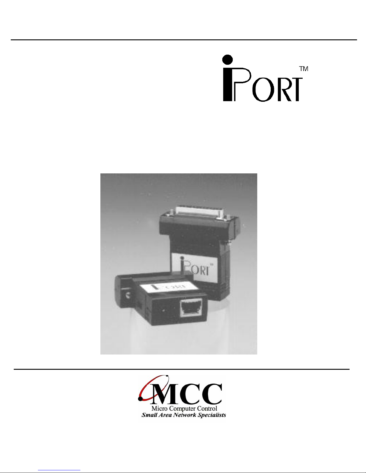
User’s Guide
Windows to I2C Bus Host Adapter
with iPort Utility Pack Software
www.mcc-us.com
Page 2

Introduction
The MCC iPort (#MIIC-201) Windows to I2C Host
Adapter, when used with appropriate Windows
application software, allows a PC to become an I
Master or Slave device, transmitting or receiving I
messages between the PC and one or more I
devices across an I
2
C Bus.
This user’s guide describes the installation and
operation of the iPort (#MIIC-201) Windows to I
2
C
2
C
2
C
2
C
Host Adapter and iPort Utility Pack Software for
Windows.
MCC products are licensed to use the I²C Bus.
Purchase of Philips I²C components conveys a license under the Philips’ I²C patent to use the
components of the I²C system, provided the system conforms to the I²C specifications
defined by Philips.
I²C is a trademark of Philips Corporation.
Page 3

Table of Contents
Part 1
Windows to I2C Bus Host Adapter
Overview ........................................................1
iPort Adapter................................................. 2
iPort Utility Pack Software ......................................2
iPort Software Development Kit for Windows (optional) ..............2
Packing Slip .....................................................2
System Requirements .............................................2
Interconnects .................................................... 3
RS-232 Serial Port Connector ................................... 3
DB-25 Serial Port Pinout .......................................3
DB-9 Serial Port Pinout ........................................ 3
+5VDC Power Jack ...........................................4
2
C Interface Connector ........................................ 4
I
Hardware Configuration ..........................................5
Pull-up Resistors.............................................. 5
Connecting to a 3.3v System ........................................5
Connecting to an SMBus System .................................... 5
Hardware Set-Up ................................................. 5
Part 2
iPort Utility Pack For Windows
Introduction to Utility Pack ........................................ 7
iPort Message Center .......................................... 7
iPort Message Manager ........................................8
System Requirements .............................................9
Software Installation ..............................................9
Introduction to Message Center ....................................10
2
C Message Operations .......................................11
I
Page 4

Introduction to Message Manager .................................. 14
2
C Message Operations .......................................15
I
Basic Set-up............................................ 16
Advanced Set-up ........................................ 17
Diagnostic Set-up .......................................18
Sending Messages ............................................... 19
Master Operations............................................19
To Master Transmit Data..................................19
To Master Receive Data ..................................20
Slave Operations............................................. 21
To Slave Transmit a message ..............................21
To Slave Receive a message: ..............................21
Uninstalling iPort Utility Pack .....................................21
Software License Agreement ......................................22
Appendix A ..................................................... 24
Page 5
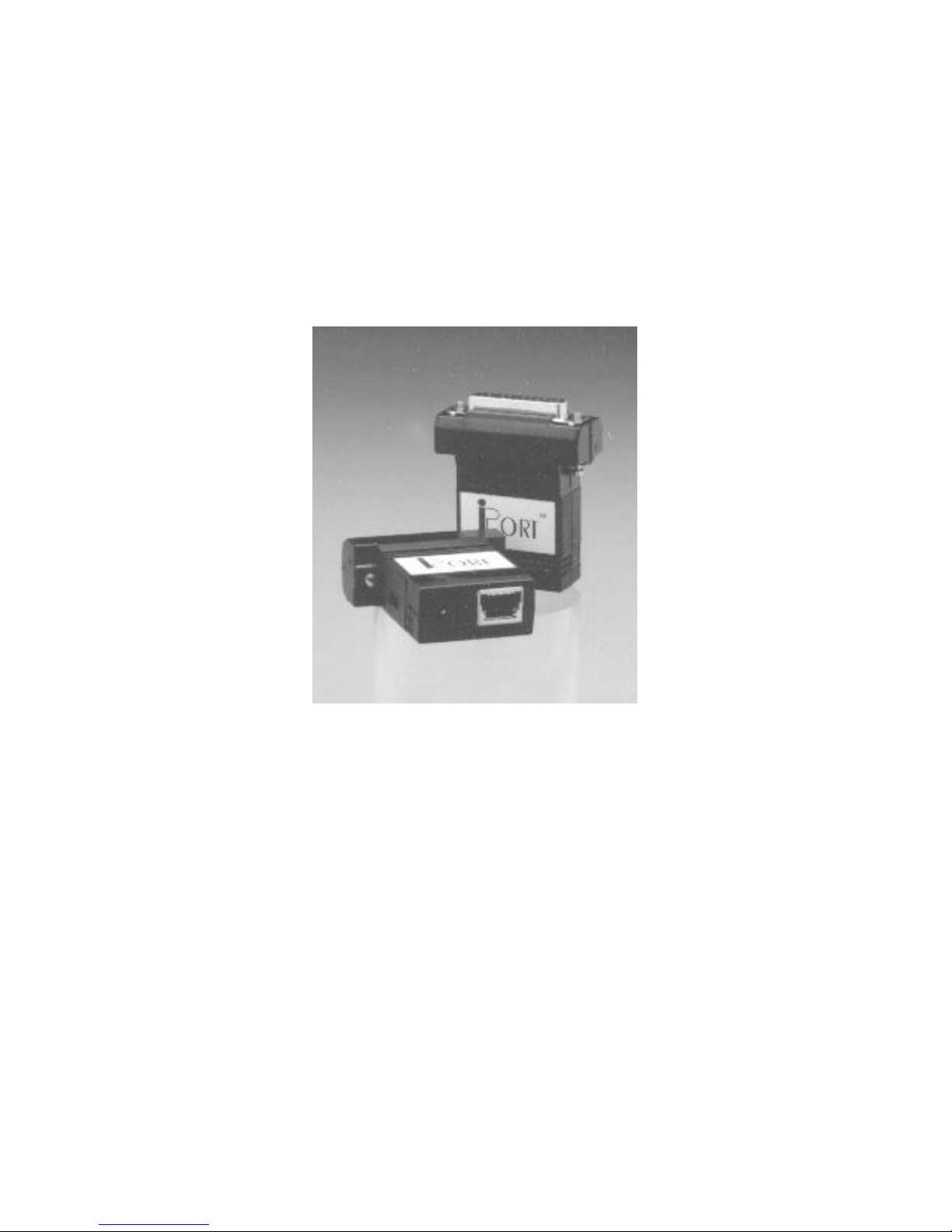
Part 1
Model MIIC-201
Windows to I
Adapter
2
C Bus Host
Page 6

Windows to I2C Bus Host Adapter
Overview
Model MIIC-201
User’s Guide
The MCC
used with appropriate Windows application software, allows a PC
to become an I
2
C messages between the PC and one or more I2C devices
I
across an I
iPort
2
C Bus.
(#MIIC-201) Windows to I2C Host Adapter, when
2
C Master or Slave device, transmitting or receiving
Product Features:
•
•
•
•
•
Turn your Windows-Based PC’s Serial Port into an I2C Port.
Get on the I2C Bus in Seconds.
Supports Bus Master and Slave, Transmit and Receive.
Includes our I2C Message Manager and Message Center
Windows Applications.
Compatible with 3.3v to 5V I2C at up to 100Kbps.
•
Build your own custom I2C applications with our I2C Software
Development Kit.
1
Page 7

The iPort system consists of the following components:
1. iPort Adapter
This adapter plugs into an RS-232 Port on a Windows-based
2
PC and generates I
iPort Utility Pack Software
2.
C Bus signals.
This software package, included with each iPort, includes the
iPort Message Manager and Message Center applications to
2
easily send and receive I
iPort Software Development Kit for Windows
3.
C Bus messages.
This optional software package includes, the iPort DLL
(Dynamic Linked Library), a programmer’s guide, and sample
programs. This package is needed if you are developing a
custom Windows software application for the iPort adapter.
Packing Slip
This package includes the following items:
• iPort (#MIIC-201) Windows to I
2
• 4 Foot I
C Interface Cable. (CAB4)
• Serial Port Cable, 9F/25M, 1 Foot Long (#C9F25M1)
• iPort User’s Guide.
• iPort Utility Pack for Windows software diskette.
• Power Supply
Standard 120VAC, 60Hz, USA Plug (#MWT-5VA)
European 220VAC, 50Hz, European Plug (#MWT-5VAE)
International 120/220/240VAC, 50-60Hz, Int.Plug selection
(#MWT-5VAI)
2
C Host Adapter.
System Requirements
a. Host computer with Windows 95 or higher
b. 1 free RS-232 Serial Port
2
Page 8
Interconnects
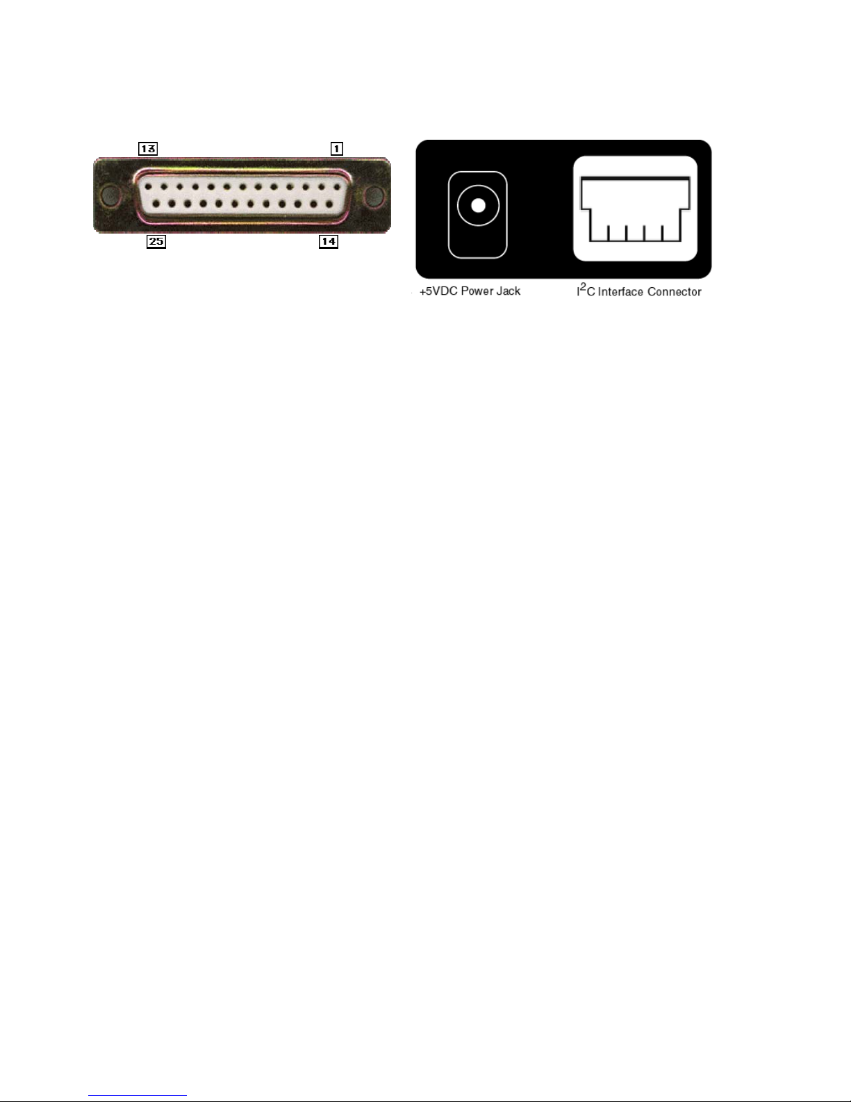
The I2C Bus Host Adapter includes three interconnections:
RS-232 Serial Port Connector
1. RS-232 Serial Port Connector
This connector provides connection to the serial port on the PC.
Use the #C9F25M1 cable to adapt the iPort to 9-pin serial ports.
DB-25 Serial Port Pinout
DB-25 Pin 2, Transmit Data from the Host Computer to the iPort
DB-25 Pin 3, Receive Data from the iPort to the Host Computer.
DB-25 Pin 4, Request to Send from the Host Computer to iPort.
DB-25 Pin 5, Clear to Send from the iPort to the Host Computer.
DB-25 Pin 7, Ground between Host Computer and iPort
DB-9 Serial Port Pinout
iPort implements the RS-232 interface using the following pins:
DB-9 Pin 3, Transmit Data from the Host Computer to the iPort
DB-9 Pin 2, Receive Data from the iPort to the Host Computer.
DB-9 Pin 7, Request to Send from the Host Computer to iPort.
DB-9 Pin 8, Clear to Send from the iPort to the Host Computer.
DB-9 Pin 5, Ground between Host Computer and iPort
3
Page 9
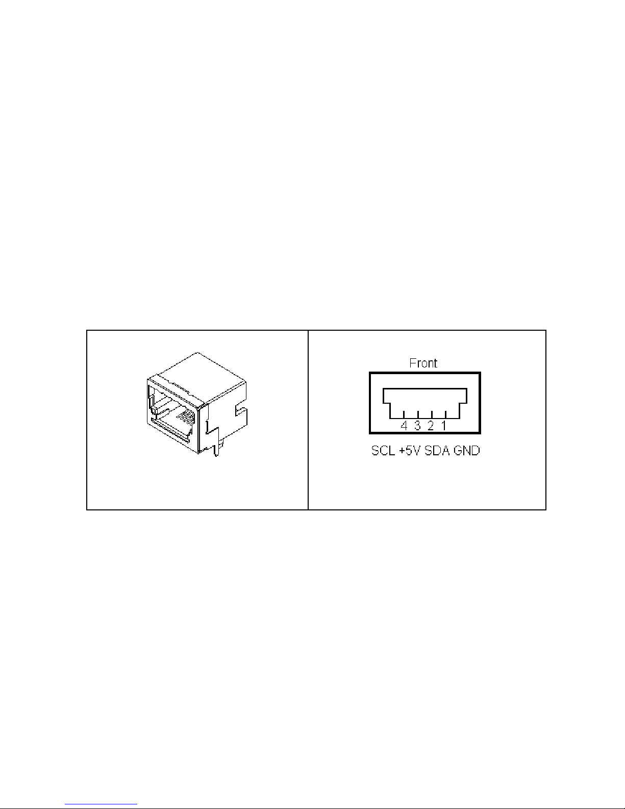
2. +5VDC Power Jack
The iPort Host Adapter can be powered in one of two ways, from
the power jack, or from the I
2
C interface connector. If the unit is
powered from the provided +5VDC Wall Transformer,
2
approximately 250ma of regulated +5VDC is available at the I
C
interface connector to power external devices. If the iPort is
2
powered from the I
C connector, the unit requires 50ma of
regulated +5VDC.
2
3. I
C Interface Connector
The iPort Host Adapter includes a four wire, positive locking,
modular connector (see Appendix A for more info on these parts)
2
for interfacing to an external I
C Bus. Lines provided include I2C
Clock (SCL), Data (SDA), Ground, and +5VDC.
Receptacle Connector
An I2C Interface Cable (White=SCL, Red=+5VDC, Green=SDA,
Black=Ground) is provided to connect to a external I
there is no standard I
one end of the cable and add a connector compatible with your
target system.
2
Additional I
C Interface Cables (4 ft., 8ft., or 16 ft.) and above
mentioned modular connectors are available from MCC. Clip Lead
cables are also available. (see Appendix A)
2
C Bus. Since
2
C Bus connector, you may want to cut off
4
Page 10

Hardware Configuration
Pull-up Resistors
The iPort Host Adapter includes a slide switch used to enable or
2
disable internal I
system must have at least one Pull-Up on the SCL and SDA lines.
Use this switch to configure the iPort appropriately for your
system.
Connecting to a 3.3v System
1. Shut off iPort internal pull-ups. (See Pull-up Resistor section)
2. Use external pull-ups to 3.3 volts.
The iPort is a 5-volt device. 3.3v is high enough for the iPort to see
a Logical 1.
C Bus 1.8K ohm Pull-Up resistors. Every I2C Bus
Connecting to an SMBus System
1. Shut off iPort internal pull-ups. (See Pull-up Resistor section)
2. Use external SMBus rated (approx. 15k ohm) pull-up resistors.
Hardware Set-Up
1. Attach your iPort(#MIIC-201) to an open ComPort on your
computer. If your ComPort has a DB9 connector, use DB-9F to
DB-25M Serial Port Adapter Cable included with your iPort to
connect.
2. Connect the power supply provided or see Interconnect Section
+5VDC Power Jack.
2
3. Connect I
C/ACCESS.bus Cable to iPort and your I2C device. If
your device does not have the matching connector(#15830064)
you can cut the end of the cable and attach the individual wires
to your device or you can purchase our clip-lead cable
(#CABCL).
5
Page 11

Part 2
iPort Utility Pack for
Windows
V5
6
Page 12
iPort Utility Pack for Windows
1. Introduction to Utility Pack
This product includes two (2) Windows applications (Message
Manager and Message Center) that help a user get started
2
sending and receiving I
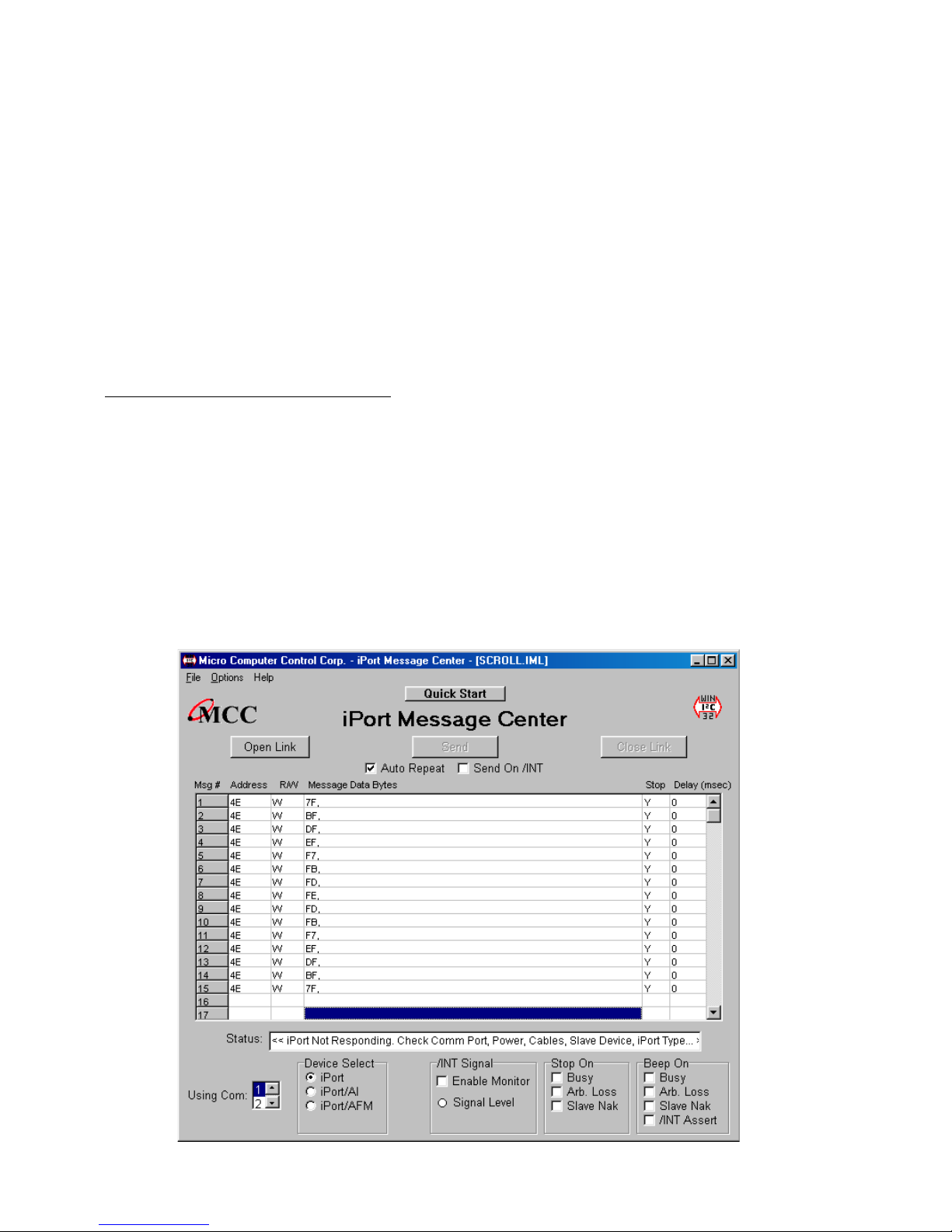
iPort Message Center
The iPort Message Center operates with all versions of the iPort
2
C Bus Host Adapter. With this program you can create, save,
I
and execute scripts of the following modes of I
C Bus messages quickly.
2
C Bus message
activity:
• Master Transmit
•Master Receive
7
Page 13
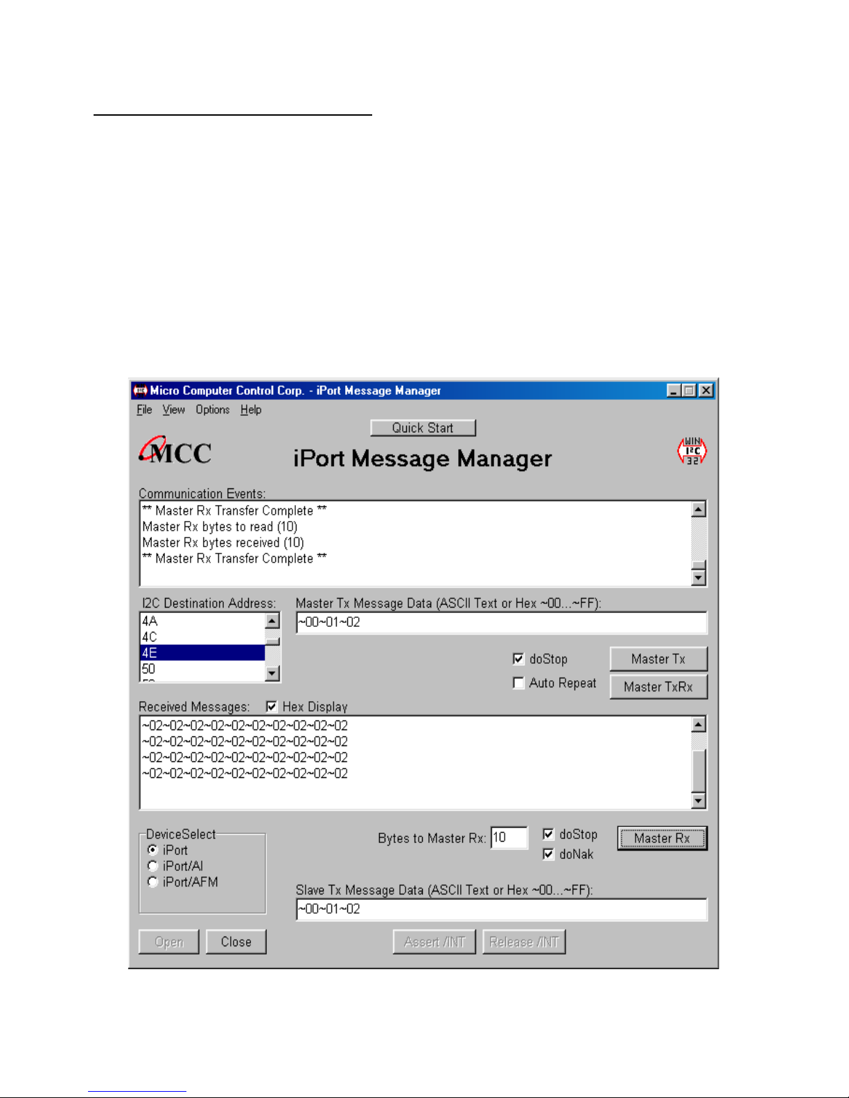
iPort Message Manager
The Message Manager operates with all versions of the iPort I2C
Bus Host Adapter. Using this program you can perform all four (4)
2
modes of I
• Master Transmit
•Master Receive
• Slave Transmit
• Slave Receive
C Bus messages activity, including:
8
Page 14

2. System Requirements
a. One of the following:
1. iPort (#MIIC-201) Windows to I
2. iPort/AI (#MIIC-202) RS-232 to I
ASCII Interface
3. iPort/AFM (#MIIC-203) RS-232 to I
with ASCII Fast Mode Interface.
b. Windows 95 or higher
c. 1 free RS-232 Serial Port.
3. Software Installatio n
Windows 95 and Above:
2
C Bus Host Adapter.
2
C Bus Host Adapter with
2
C Bus Host Adapter
1. Insert software distribution diskette into floppy drive.
Run. Type “A:SETUP.EXE”.
2. Select Start
*
3. Follow instructions on screen.
9
Page 15

iPort Message Center for Windows
Introduction to Message Center
The iPort Message Center supports I2C Master Transmit and
2
Receive activities for all versions of the iPort I
Adapter. With this program you can create, save, and execute
2
scripts of I
C Master messages.
The MCC iPort Message Center Software, when used with an
MCC iPort allows a PC to become an I
2
receiving device, sending I
2
or more I
C devices across an I2C Bus.
C messages between the PC and one
2
C Master transmitter or
C Bus Host
The iPort Message Center is designed to be a simple application
for experimenting with I
1. Edit a list of I
2
C Master Transmit or Receive Messages.
2. Save and/or Load a list of I
3. Transmit the current list of I
2
C messages. It provides methods to:
2
C Master messages to/from disk.
2
C Master messages, with the
option to auto repeat upon completion, or send on INT assert
(low). (iPort/AFM only)
2
Each iPort Message Center I
C message can include up to 32
bytes of 8-bit data, with an optional time delay at the completion of
each message.
10
Page 16
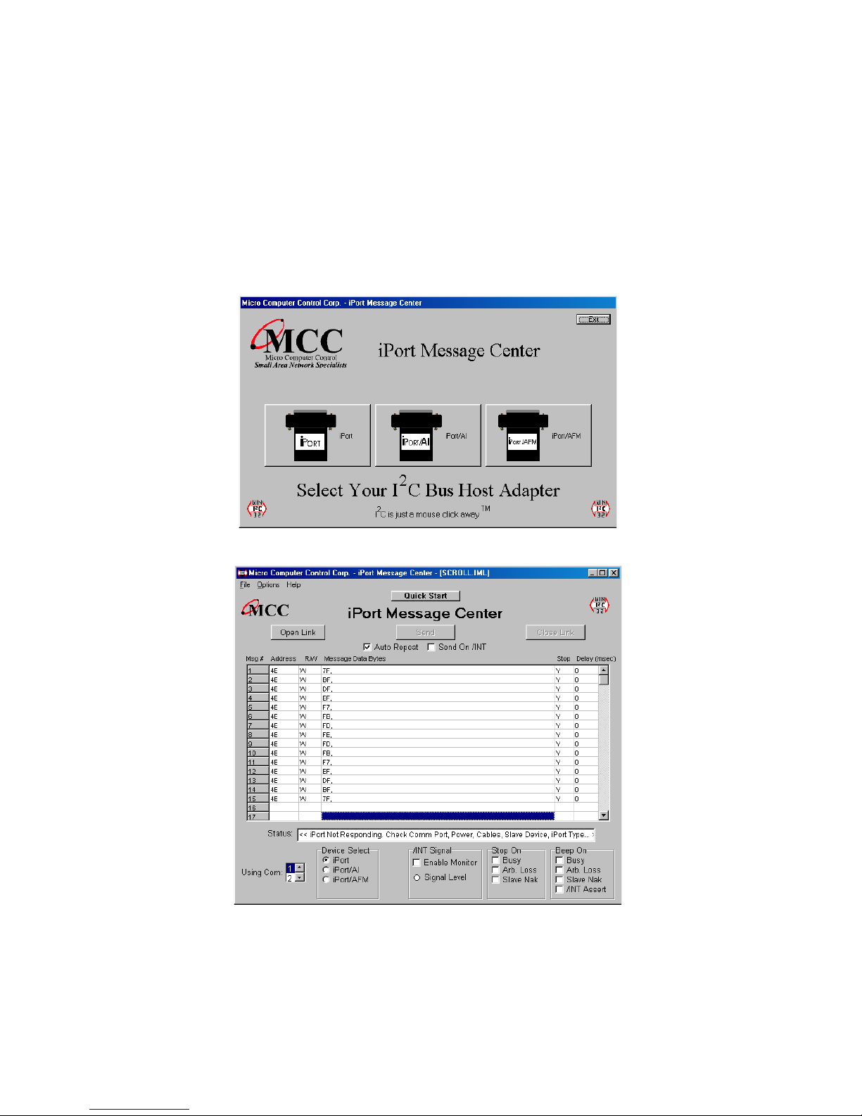
I2C Message Operations
In order to communicate with another I2C device, a user must take
the following steps:
Programs *iPort Utility Pack*iPort Message Center
1. Start
Select which device you are operating with by choosing the
2.
corresponding image (Opening Screen), or the correct checkbox
on the main application.
*
Opening Screen
Main Application
The Main Application screen is opened by selecting an image on
the Opening Screen.
11
Page 17
3. Select the PC ComPort where the iPort is connected to your
computer.
2
4. Use the Options menu to override default Baud Rate and I
C
Bus Clock rate settings.
5. Establish a link to the iPort with the Open button. The iPort
2
Message Center software sets the iPort’s own I
C Slave
address to 0xFE.
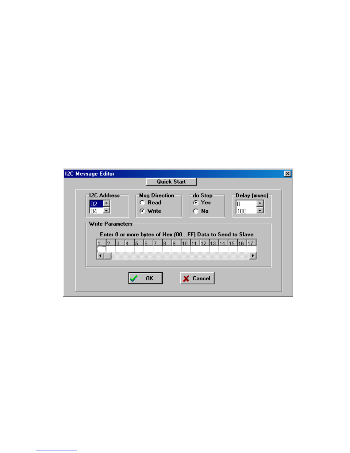
6. To open an existing message list, click File|Open List on the
menu bar. To enter or edit a message List, open the “I
2
C
Message Editor” screen, by double clicking on a message row
in the spreadsheet.
Now you can:
2
a. Set the I
C address (i.e. 4C, 4E, etc.)
b. Set Msg Direction (Read or Write)
c. Do stop (yes or no, Repeated starts)
d. Set time delay (delay in msec, controls speed of activity).
e. Write message data (from 00 to FF) or read count.
f. Click OK.
Repeat above steps for additional messages.
12
Page 18

You can insert a new message between existing messages by
clicking once on a message below where you want to insert, press
2
the “Insert” button on your keyboard, this will bring up the I
C
Message Editor screen, set all information and click OK.
7. On the main screen, click on Send to transmit the current list
2
of I
C Master messages, with the option to auto repeat upon
completion, or send on INT assert (low). (iPort/AFM only)
Once the link has opened successfully, you are now an active I2C
node. Messages are entered into the message spreadsheet and
are transmitted upon clicking the Send button. Data received as
part of a Master Receive message replaces the 0xFF placeholders
in the message spreadsheet control.
If you get a “Slave Not Acknowledging” message in the
Communications Events window, this could mean you have the
2
wrong address in the I
C Destination Address, or the device is not
answering to its address.
13
Page 19

iPort Message Manager Software for Windows
Introduction to Message Manager
The MCC iPort Message Manager Software, when used in
2
conjunction with an MCC iPort allows a PC to become an I
2
Master or Slave device, transmitting or receiving I
2
between the PC and one or more I
C devices across an I2C Bus.
C messages
The iPort Message Manager is designed to be a simple application
for experimenting with I
1. Set the device’s I
2
C messages. It provides methods to:
2
C Slave address, General Call Enable, and
other operating parameters.
C
2. Master Transmit ASCII text or Hex [~00...~FF] data to a
2
specified I
3. Master Receive data from a specified I
C Slave Receiver device.
2
C Slave Transmitter
device.
4. Perform Master Read after Write operation.
2
5. Slave Transmit data to a requesting I
C Master Receive device.
6. Display Slave Receiver data.
__
7. Assert or release the INT signal (iPort/AFM only).
2
Each iPort Message Manager I
C message can include up to 23
bytes of 8-bit ASCII binary data, although the iPort itself is capable
2
of sending or receiving I
C messages up to 64K bytes in length.
14
Page 20
I2C Message Operations
In order to communicate with another I2C device, a user must take the
following steps:
1.
Starting the program
Start
2.
Select iPort Device
Programs *iPort Utility Pack * iPort Message Manager
*
:
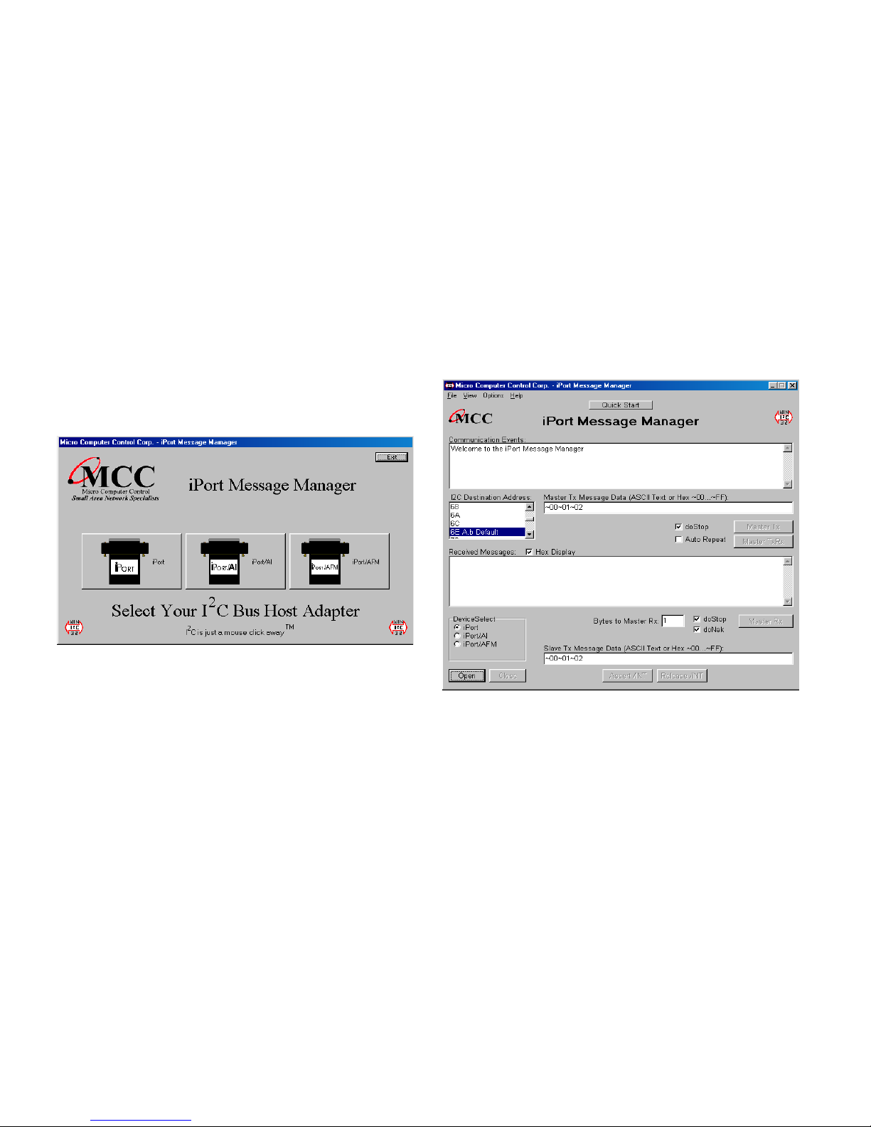
Select which device you are operating with by choosing the
corresponding image (Opening Screen), or the correct checkbox on the
main application.
Opening Screen
Main Application
The Main Application screen is opened by selecting an image on the Opening Screen.
3.
Establish iPort Link
On the Message Manager main screen, click the Open button to view the
Set Up Screen. You now have three options of set-up for the Message
Manager, Basic Set-up, Advanced Set-up, and Diagnostic Set-up.
15
Page 21
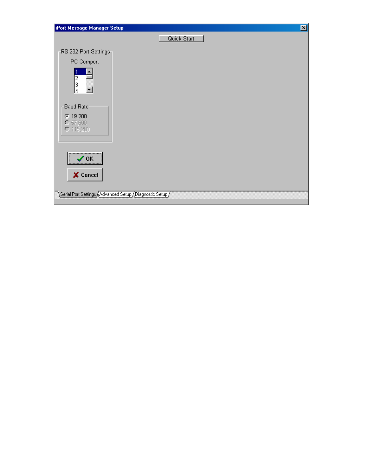
Basic Set Up Screen
Basic Set-up
Select the PC ComPort attached to your iPort and the baud rate, then click
OK. The Communications Events window on the Main Screen should report
2
C Open Successful”. If this message does not appear, check the iPort
“I
connections and power.
16
Page 22
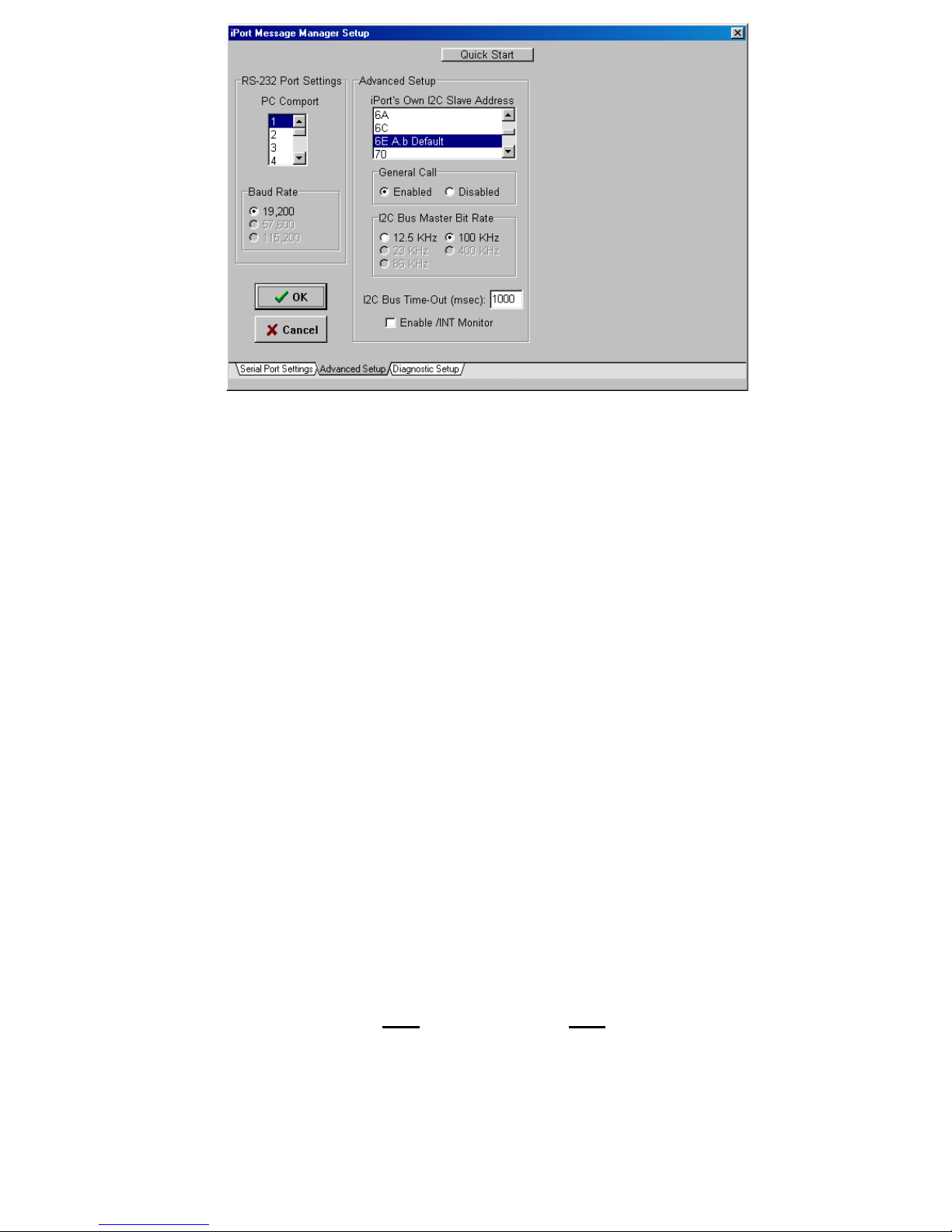
Advanced Set Up Screen
Advanced Set-up
On the Advanced Set-up screen you can set the following parameters:
1. iPort I
Select iPort’s I
2
C Slave Address
2
C slave address. iPort will acknowledge messages sent
to this address.
2 iPort General Call
2
Enabled allows iPort to respond to the I
General call is used to broadcast an I
3. I
2
C Bus Master Bit Rate (iPort, iPort/AFM)
C general call address (00).
2
C message to multiple devices.
The speed of the Bus will run. 100KHz is standard mode, 400kHz is fast
mode. Use other rates if you are having trouble talking to a very slow
slave device.
2
4. I
C Bus TimeOut (Msec) (iPort, iPort/AFM)
Control how long iPort will wait before reporting an I
2
C Bus
intra-message timeout. (0=None, 1...32767 msec)
___
5. Enable INT monitor (iPort/AFM only)
Enables monitoring of the INT signal state. INT state changes are
reported in the main screen Communications Events window.
17
Page 23
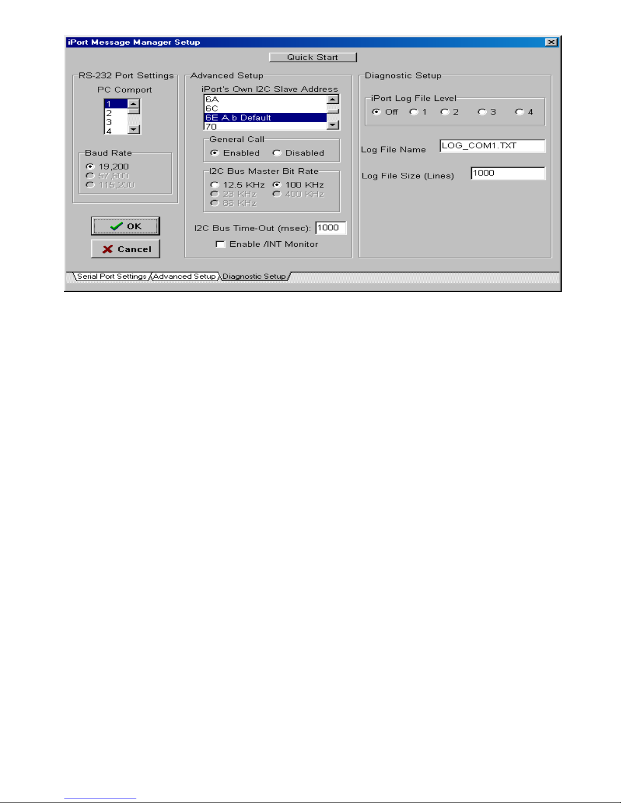
Diagnostic Set Up Screen
Diagnostic Set-up
(iPort Only)
On the Diagnostic Set-up screen you can set the following parameters:
1. iPort Log File Level
Select iPort logging level.1 gives minimal info, 4 is verbose. Use the log
file to troubleshoot communication problems.
2. Log File Name
iPort log file name if enabled.
3. Log File Size (Lines)
iPort log file length if enabled.
4. Set the Destination Slave Address
2
On the main screen, use the I
C Destination Address list control to set the
slave address of the device you want to communicate with.
Additional operating information is available by viewing the Status and Log
File. (Option available only for the iPort).
18
Page 24
Sending Messages
Master Operations
1.
To Master Transmit Data
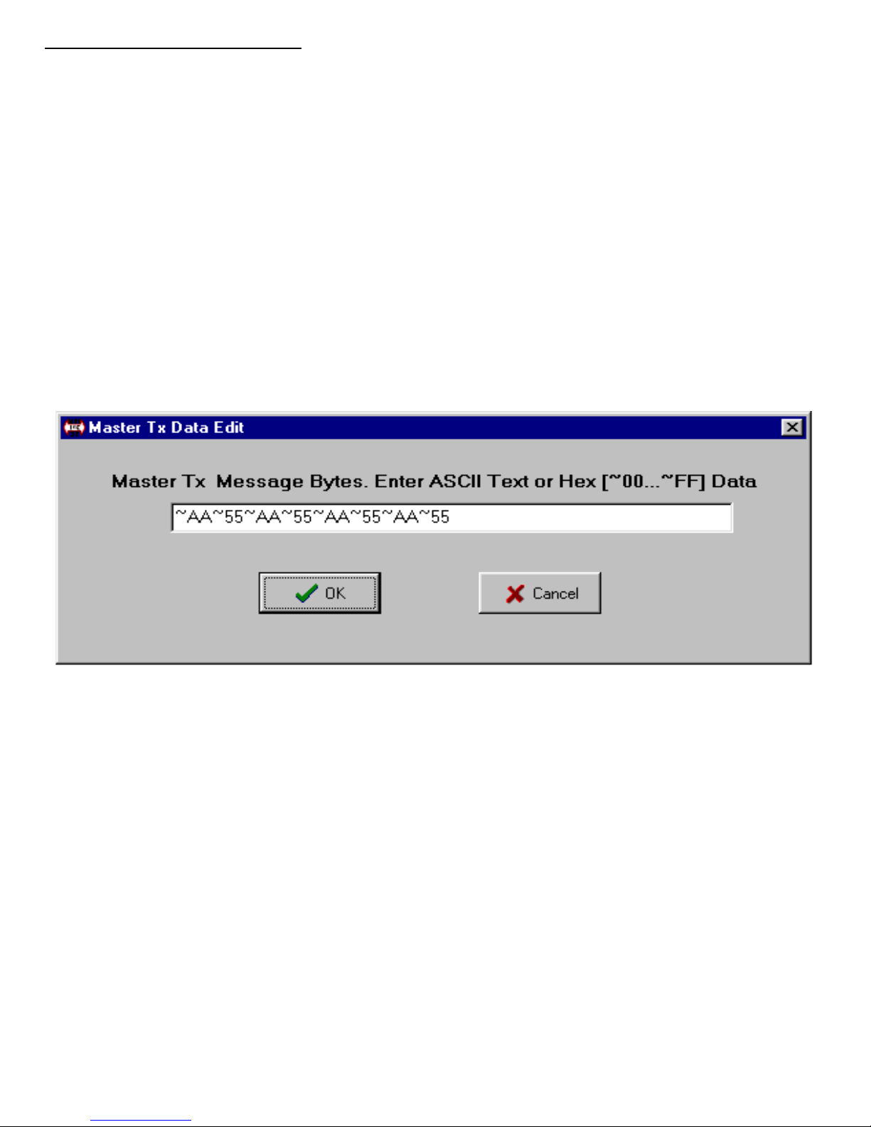
On the main screen, set the Master Tx Message Bytes edit box to the data
you want to send by single clicking on the box. For example: To send a
0x05(hexadecimal) to the device, enter ~05 in the edit box. Click Ok and
then the Master TX button to send the message. The Communications
Events window on the main screen should report “Master TX Complete”. If
this message does not appear, check the slave device address,
connections, and power.
Example:
to send message 0x01, 0x02, 0x03, type in ~01~02~03.
You have the option to Auto Repeat a transmitted message upon completion
by checking the Auto Repeat box. You may also uncheck the DoStop check
box to send a message without a stop. This will allow you to send messages
with repeated starts.
19
Page 25
2.
To Master Receive Data
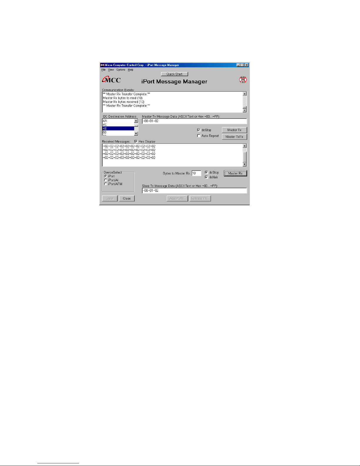
On the main screen, use the I
2
C Destination Address list control to set the
slave address of the device you want to communicate with.
Main Application Screen
On the lower part of the main screen, set the Bytes to MasterRx edit box to
the number of bytes you want to read. For example: Set this to 1 to read a
single byte. Click on the Master RX button to receive the message. Data
received from the slave is displayed in the Received Messages text box on
the main screen. The Communications Events window should report “Master
RX Transfer Complete”. If this message does not appear, check the slave
device address, connections, and power.
If you get a “Slave Not Acknowledging” message in the Communications
2
Events window, this could mean you have the wrong address in the I
C
Destination Address, or the device is not answering to its address.
You have the option to Auto Repeat a transmitted message upon completion
by checking the Auto Repeat box. Also, you may uncheck the DoStop check
box to perform repeated starts. Another option you have is to do “DoNak”
(iPort Only), which allows you to Ack or Nak the last byte coming from a
Slave Transmitter. Some Slave Transmitter Devices require a Nak on the
final byte going across the bus.
20
Page 26

Slave Operations
To Slave Transmit a message:
Enter data to be transmitted in the Slave Tx Message Bytes control by single
clicking. Binary data bytes are entered using a three-character
Hex-Equivalent format (~00 ... ~FF), you may also type in ASCII text. These
bytes are automatically transmitted when a Slave Transmit Request is
received from a Master device.
To Slave Receive a message:
Data bytes received from a Master Transmitter are automatically displayed in
the Received Message window. Received binary data is displayed using a
three-character Hex-Equivalent format (~00 ... ~FF). By selecting the HexDisplay checkbox, the data is displayed as Hexadecimal data .
Uninstalling iPort Utility Pack
Click, Start | Programs | iPort Utility Pack | uninstall.
Follow the on screen instructions.
21
Page 27

Software License Agreement
BY INSTALLING THIS SOFTWARE, YOU ARE AGREEING TO BECOME
BOUND BY THE TERMS OF THIS AGREEMENT. IF YOU DO NOT
AGREE TO THE TERMS OF THIS AGREEMENT, PROMPTLY RETURN
THE ENTIRE PRODUCT WITHIN 7 DAYS WITH ALL ITS CONTENTS TO
THE PLACE OF PURCHASE, WITH A NOTE THAT YOU RETAIN NO
COPIES OF THE SOFTWARE OR PRINTED MATERIALS, FOR A FULL
REFUND.
The computer files and materials supplied in this package are
2
non-exclusively licensed to Purchasers of the MCC iPort I
Distribution of the MCC iPort Utility Pack software (IMSGCTR.EXE) and any
other computer files supplied as part of the MCC iPort Utility Pack, is strictly
limited to employees of the Purchasing Company.
C Host Adapter.
Violation of any of the above provisions automatically terminates the
Purchaser's license.
Life Support Applications
MCC Products are not designed for use in life support appliances, devices,
or systems where the malfunction of a MCC Product can reasonably be
expected to result in a personal injury.
Limited Warranty
MCC warrants, as the sole warranty, that the disks on which the Software is
furnished will be free of defects in materials and workmanship under normal
use and conditions for a period of thirty (30) days from the date of purchase.
No distributor, dealer, or any other entity or person is authorized to expand
or alter this Agreement.
MCC does not warrant that the functions contained in the Software will be
uninterrupted or error-free. Except as stated above in this paragraph, the
Software is provided as is without warranty of any kind either expressed or
implied, included but not limited to the implied warranties of merchantability
and fitness for a particular purpose. The Purchaser assumes entire risk as it
22
Page 28

applies to the quality and performance of the Software. Should the Software
prove defective, the Purchaser (and not MCC, authorized MCC distributors,
or dealers) assume the entire cost of all necessary servicing, repair or
correction.
Limitation of Remedies and Damages
MCC's entire liability and remedy will be the replacement of any disks not
meeting MCC "Limited Warranty" explained above.
In no event will MCC be liable for any damages direct, indirect, incidental, or
consequential, including damages for lost profits, lost savings, or other
incidental or consequential damage arising out of the use or inability to use
such Software, even if MCC has been advised of the possibility of such
damages or for any claim by any other party. In no event will MCC's liability
of damages to the Purchaser or any other person ever exceed the amount of
the license fee paid by the Purchaser to use the Software regardless of the
form of the claim.
This Agreement is governed by the laws of the State of New Jersey USA
(except federal law governs copyrights and registered trademarks.) If a
provision of this Agreement is deemed invalid by any court having
jurisdiction, that particular provision will be deemed deleted and will not
affect the validity of any other provision of this Agreement.
TEL(609)466-1751 FAX (609)466-4116
EMAIL [email protected]
For the latest product information, application notes, and free software
updates visit our Web Site at:
http://www.mcc-us.com
23
Page 29

Appendix A
Interface Connector and Plug Information
MCC uses two (2) different connectors and plug assemblies. These parts are all
compatible with one another and are interchangeable.
Connectors
Molex SEMCONN ACCESS.bus Receptacle Connector
Molex Part # 15-83-0064
AMP SDL (Shielded Data Link) Connectors for ACCESS.bus
AMP Part # 4-943197-1
Plugs
Molex SEMCONN ACCESS.bus Plug
AMP SDL (Shielded Data Link) Plug for ACCESS.bus
Bush Amp Part # 520851-1
Ferrule Amp Part # 520433-1
SDL (Shell) Amp Part # 520461-1
SDL (Shell) Amp Part # 520460-1
SDL Amp Part # 4-520424-1
Additional Cables Available
MCC Part # CAB4 I
MCC Part # CAB8 I
MCC Part # CAB16 I
MCC Part # CABCL I
2
C Interface Cable, 48inches (4ft)
2
C Interface Cable, 96 inches (8ft)
2
C Interface Cable, 192 inches (16ft)
2
C and SMBus Clip Lead Cable
Molex Part # 15-83-1564
24
 Loading...