

Page 1
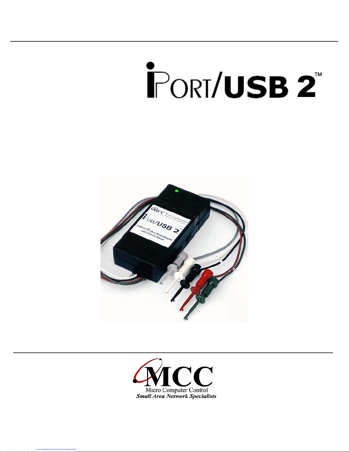
User’s Guide
USB to I2C Host Adapter
with Circuit Sense
™
www.mcc-us.com
Page 2
Introduction
The MCC iPort/USB 2™ USB to I2C Bus host adapter with Circuit Sense allows
2
any Windows, Linux, or Mac OS X host computer to become an I
2
Slave device, transmitting or receiving I
2
one or more I
C devices across an I2C Bus.
C messages between the host computer and
C Master or
This user’s guide describes the installation and operation of the iPort/USB 2 host
adapter, Virtual Communication Port (VCP) driver, iPort Utility Pack Software for
Windows, and includes the Programmer’s Reference for creating custom
applications.
2
Are you new to I
C? Want to know more? We suggest you review “What is I2C?” at
www.mcc-us.com/I2CBusTechnicalOverview.pdf.
This MCC product uses NXP (Philips) components and is licensed to use the I²C
Bus.
“Purchase of Philips I²C components conveys a license under the Philips’ I²C patent
to use the components of the I²C system, provided the system conforms to the I²C
specifications defined by Philips.”
I²C Bus is a trademark of NXP (Philips) Corporation.
28-JAN-2019
Page 3

Copyright© 2019 by Micro Computer Control Corporation. All rights are reserved.
No part of this publication may be reproduced by any means without the prior
written permission of Micro Computer Control Corporation, PO Box 275,
Hopewell, New Jersey 08525 USA.
DISCLAIMER: Micro Computer Control Corporation makes no representations or
warranties with respect to the contents hereof and specifically disclaims any implied
warranties of merchantability or fitness for any particular purpose. Further, Micro
Computer Control Corporation reserves the right to revise the product described in
this publication and to make changes from time to time in the content hereof
without the obligation to notify any person of such revisions or changes.
WARNING - Life Support Applications: MCC products are not designed for use
in life support appliances, devices, or systems where the malfunction of the product
can reasonably be expected to result in a personal injury.
WARNING - Radio Frequency Emissions: This equipment has been tested and
found to comply with the limits for a Class A digital device, pursuant to part 15 of
the FCC rules. These limits are designed to provide reasonable protection against
interference when the equipment is operated in a commercial environment. This
equipment generates, uses, and can radiate radio frequency energy and, if not
installed and used in accordance with the instruction manual, may cause
interference to radio communications. Operation of this equipment in a residential
area is likely to cause interference, in which case the user will be required to correct
the interference at his own expense.
WARNING - Electrostatic Discharge (ESD) Precautions: Any damage caused by
Electrostatic Discharge (ESD) through inadequate earth grounding is NOT covered
under the warranty of this product. See the “Electrostatic (ESD) Precautions”
section of this guide for more information.
Created in the United States of America
Page 4

Table of Contents
iPort/USB 2, USB to I2C Bus Host Adapter .............................1
1 Overview .......................................................2
iPort/USB 2 Product Features .......................................3
iPort/USB 2 Package ..............................................4
System Requirements .............................................5
2 Interconnects ....................................................5
USB Connector ..................................................5
Virtual Communications Port (VCP) ...............................5
2
C Mini Interface Connector .......................................6
I
/INTerrupt Signal.................................................7
3 Hardware Configuration ...........................................8
Circuit Sense™ ..................................................8
Pull-up Resistors .................................................8
Connecting to an SMBus Target System...............................9
4 ESD (Electrostatic Discharge) Precautions .............................9
Host Computer Grounding ........................................10
Grounding Solutions .............................................10
5 Driver Software Set-Up...........................................11
Driver Install ...................................................11
Driver Update ..................................................11
Driver Uninstall.................................................11
6.Hardware Set-Up ................................................12
USB Connection ................................................12
2
C Bus Connection ..............................................12
I
7. Software Support ................................................13
2
C Bus Communication Utilities ...................................13
I
iPort Utility Pack for Windows ...................................13
iPort Message Center ........................................13
iPort Message Manager ......................................13
2
iBurner I
2
C Bus Software Development Tools................................14
I
C Bus EEPROM Programmer............................13
Page 5

MS.NET Class Library .........................................14
LabVIEW VI Library ..........................................14
ASCII Command Interface ......................................14
iPort/USB 2 Revision Report.........................................15
Additional Information..............................................15
2
Appendix A - I
C Connector Information ...............................16
Declaration of Conformity ...........................................17
Page 6
iPort/USB 2, USB to I2C Bus Host Adapter
USB to I2C Bus
Host Adapter
with
Circuit Sense
™
User’s Guide
Model: MIIC-208
1
Page 7
1 Overview
2
The iPort/USB 2, MCC’s USB to I
C Bus host adapter with Circuit Sense, allows
any Windows, Linux, or Mac OS X host computer to become an I
2
Slave device, transmitting or receiving I
2
one or more I
C devices across an I2C Bus. Circuit Sense, our new I2C Bus voltage
C messages between the host computer and
2
C Bus Master or
sensing technology, allows the iPort/USB 2 to work with the latest I
at voltages an low as 0.5 volts.
2
C Bus devices
2
Page 8

1.1 iPort/USB 2 Product Features
• OS Support: Windows, Linux, Mac OS X
• High Performance Processor Increases Throughput (2x to 200x).
• USB Bus Powered with USB 2.0 Type B Jack.
• Built-in ESD, Over-voltage, and Reverse-voltage Protection.
• Switch Controlled Properties:
2
C Bus Power Source (3.3v or 5v @100ma).
•I
2
C Bus Voltage Sense (0.5v to 5v, Enable or Disable).
•I
2
C Bus Pull-Ups (1.8K ohm, Enable or Disable).
•I
• Software Controlled Properties:
2
C Bus Master Clock Rates: 23KHz, 86KHz, 100KHz Std, 400KHz Fast
•I
2
C Bus General Call Enable
•I
2
C Bus Time-Out (0-32K ms)
•I
2
C Bus Interrupt Signal Control (Assert, Release, Monitor)
•I
• Host Communication Flow Control (XON/XOFF or RTS/CTS)
• User Interface Echo/Prompt Enable
• User Data Format (HEX or ASCII/HEX)
2
• Supported I
C Bus Activities:
• Master and Slave Functions
• Transmit, Receive, and Tx/Rx Data Functions
• Multi-Master Arbitration Loss Detection
• Clock-stretch Detection
• Bus Time-Out Detection
• Interrupt Signal Generation and Detection
• 7-bit Slave Address Generation and Detection
• Up to 32K data bytes in a single message
• SMBus Packet Error Detection
2
• eXtended Commands for 2-Wire, "I
C-Like" Low-level SCL/SDA Signal
Control
• Software Support:
• Virtual ComPort Drivers
• Application Software
• Software Development Tools
• Compatible with existing iPort/AI, iPort/AFM, iPort/USB, i2cStick, and
iPort/LAN applications.
• USB-IF (Full-Speed) and MS WHQL Certified.
• US-FCC and EUR-CE EMC Compliant.
• RoHS/Lead-Free Compliant.
3
Page 9
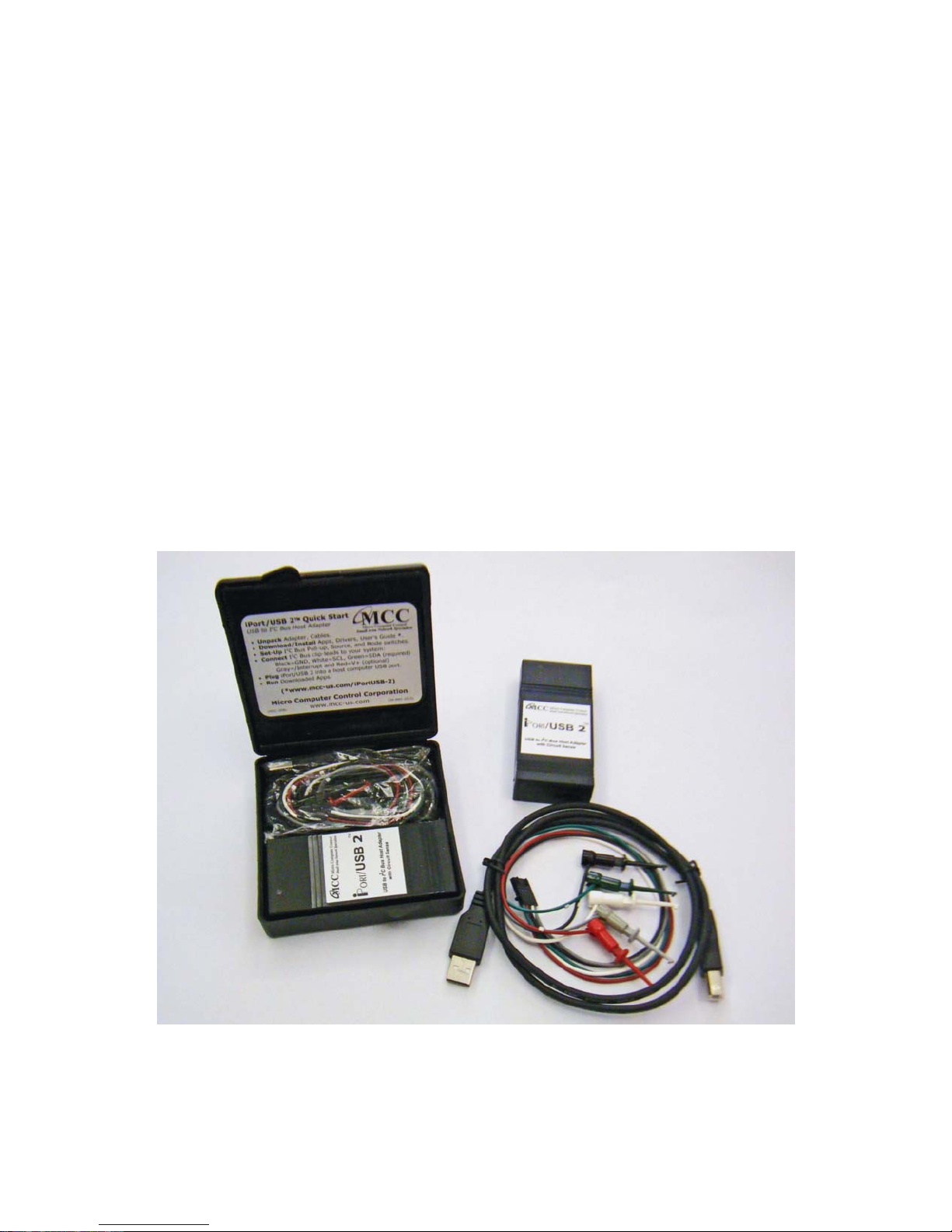
1.2 iPort/USB 2 Package
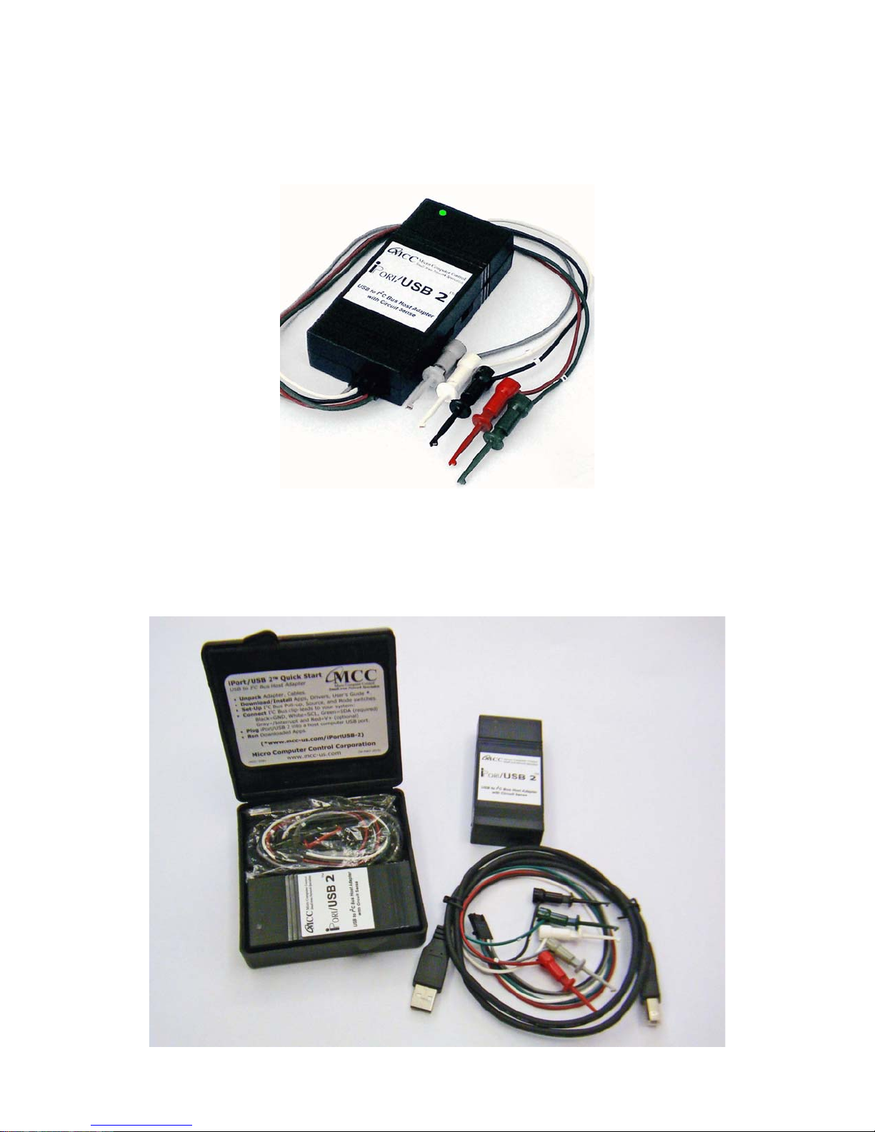
The iPort/USB 2 package includes the following items:
2
• iPort/USB 2, USB to I
C Bus Host Adapter.
• iPort/USB 2 Mini Clip-lead Cable.
• iPort/USB 2 USB 2.0 A/B Interface Cable.
• iPort/USB 2 Quick Start Guide.
• iPort/USB 2 Travel Case.
• Online Items*
• iPort/USB 2 Datasheet
• iPort/USB 2 User’s Guide (this document)
• iPort/USB 2 Virtual ComPort Drivers
• iPort Utility Pack Software
• Application Software.
• Software Development Tools
(* www.mcc-us.com/iPortUSB-2)
4
Page 10
1.3 System Requirements
a. A host computer with one free USB port or self-powered USB hub.
b. A host computer with one of the following operating systems:
• Windows XP+
• Linux 2.6+
• Mac OSX 10.5+
2 Interconnects
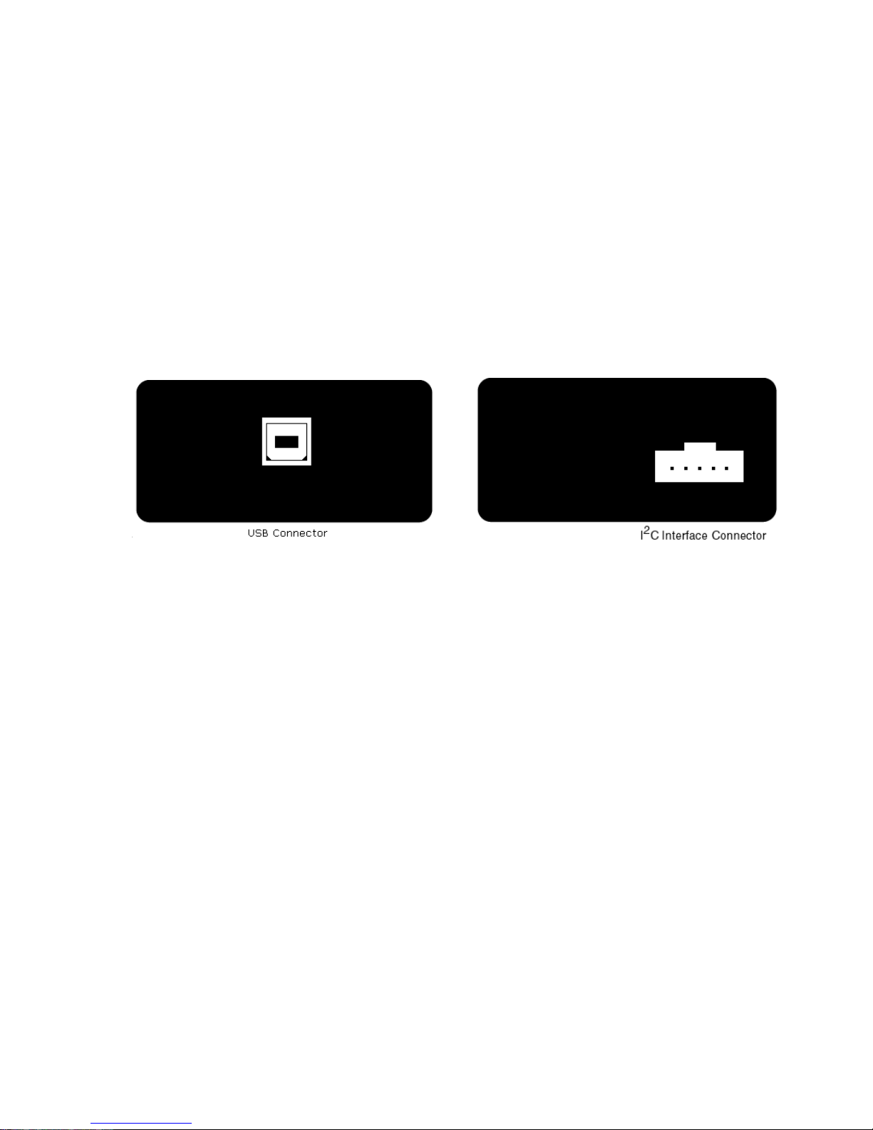
The iPort/USB 2 includes two interconnections:
2.1 USB Connector
2
A USB 2.0 Type B Jack provides connection from the I
C Bus host adapter to a
USB port on the host computer or self-powered USB hub.
The iPort/USB 2 operates as a high-power (>100 mA) bus-powered USB device,
2
with up to 100 mA of (user optional) switch-selectable 3.3v or 5v for I
C Bus target
system power.
2.1.1 Virtual Communications Port (VCP)
The iPort/USB 2 uses a Virtual Communications Port (VCP) interface to
communicate with a host computer. The VCP interface is created on the host
computer via a software driver loaded on the host computer. Drivers are available
for several operating systems. These drivers can be installed separately, or while
installing the iPort Utility Pack.
5
Page 11

The drivers and installation instructions are available online at the following web
address:
www.mcc-us.com/iPortUSB-2
After the driver software is installed, plug the iPort/USB 2 into a host computer
USB port. Upon detecting the device, the operating system will automatically load
the driver and create a new “virtual” serial port for communicating with the
iPort/USB 2. Once installed, application programs running on the host computer
can communicate with the iPort/USB 2 via the operating system serial port
Application Program Interface (API).
The iPort/USB 2 VCP includes the following communication signals:
• TX - Transmit Data ( Host Computer to iPort/USB 2).
• RX - Receive Data ( iPort/USB 2 to Host Computer).
• RTS - Request to Send (Host Computer to iPort/USB 2).
• CTS - Clear to Send (iPort/USB 2 to Host Computer).
Serial communications flow-control options include X-ON/X-OFF (default) or
RTS/CTS. The flow-control method used by a host computer application should
match the flow-control method selected for use by the iPort/USB 2 host adapter.
2
2.2 I
The iPort/USB 2 I
C Mini Interface Connector
2
C Bus host adapter includes a five wire (1x5) 2.54 mm (.100"),
positive locking, shrouded header receptacle connector (see Appendix A) for
2
interfacing to an external I
2
C Clock (SCL)
•I
2
C Data (SDA)
•I
2
C /INTerrupt
•I
C Bus. Interface lines provided include:
• Ground
• +V
2
Minimum wiring for I
C Bus communications include I2C Bus Clock, Data, and
Ground. Use of the /INTerrupt and +V wires in the I
optional.
NOTE: See the Hardware Configuration section below for additional information
2
C Interface connector are user
6
Page 12
on configuring the I2C Bus interface.
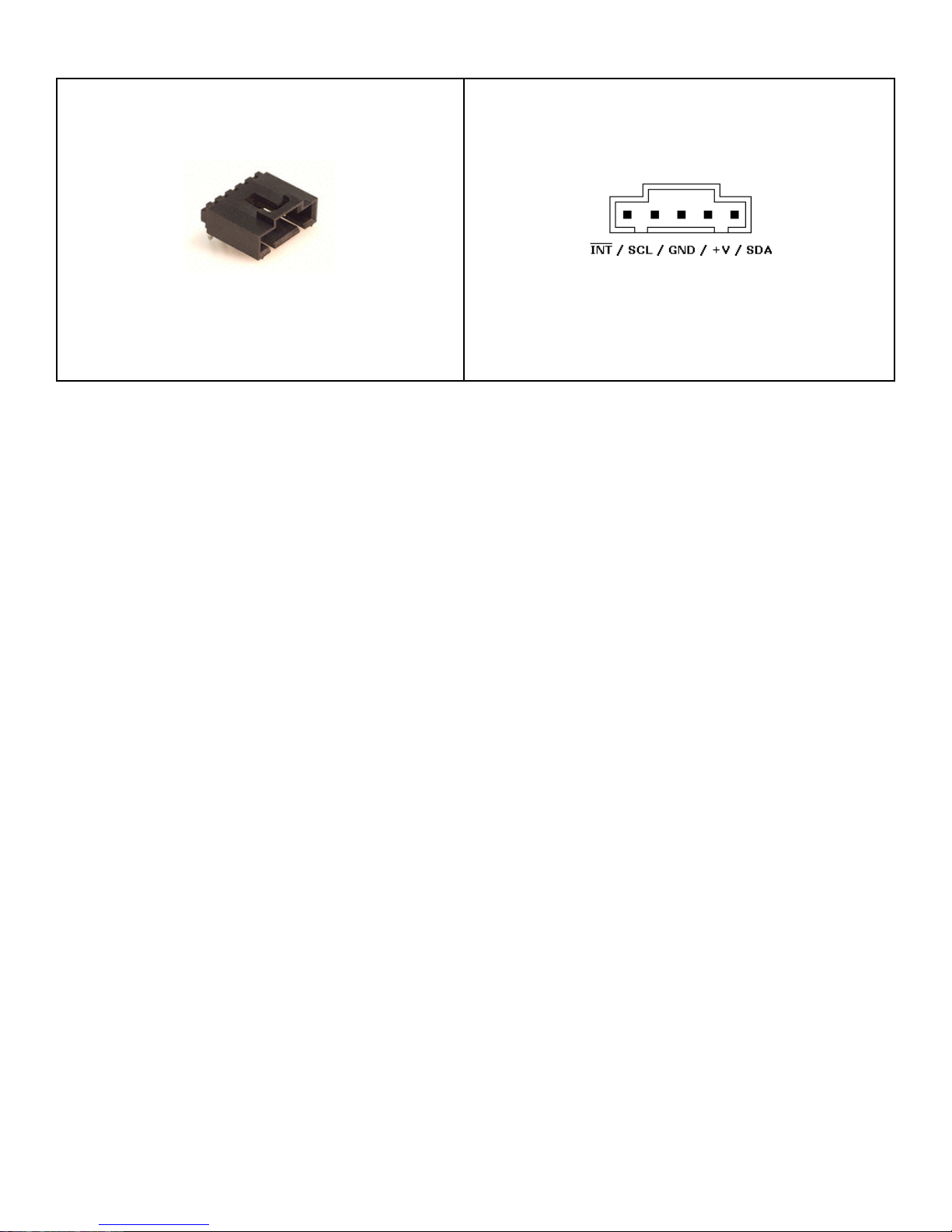
I2C Bus Mini Interface Receptacle
2
C Bus Mini-Clip-Lead cables are available to connect the iPort/USB 2 adapter to a
I
Mini Interface Receptacle Pinout
target system. Each clip-lead is identified (White=C=SCL, Red=V=+V,
Green=D=SDA, Black=G=Ground, Gray=(no mark)=/INTerrupt).
2
C Bus Mini-Interface cables with two Mini Interface plugs are also available to
I
2
connect the I
C adapter to an external I2C Bus.
2.3 /INTerrupt Signal
2
The /INTerrupt signal is an extra pin found on some I
C devices. The /INT signal
allows a slave-only device to attract the attention of a bus master device by
lowering the /INT signal to a logical low voltage level.
The iPort/USB 2 provides an open-collector /INT signal which can be connected to
a corresponding pin on a bus master or slave device. The /INT signal allows the
iPort/USB 2 to participate in interrupt signaling between master or slave devices.
The iPort/USB 2 generates an I
an iNterrupt Assert command from the host computer. The interrupt signal is
released (/INT = high) when the iPort/USB 2 is addressed as an I
device, or an iNterrupt Release command is received from the host computer.
Interrupt monitoring is enabled upon receiving an Enable /INT Monitor command
from the host computer. Interrupt monitoring causes the iPort/USB 2 to monitor the
/INT signal level, and automatically send a notification to the host computer when
the /INT signal changes state.
2
C Bus interrupt assert (/INT=low) upon receiving
2
C Bus slave
7
Page 13

3 Hardware Configuration
3.1 Circuit Sense
™
The iPort/USB 2 introduces MCC’s Circuit Sense technology. Circuit Sense allow
2
the I
C interface +V wire can operate in two modes, Power Source Mode and
Voltage Sense Mode. Mode selection is controlled by the MODE slide switch on
the side of the unit enclosure.
• Power Source Mode - The +V wire can supply power (3.3v or 5v @ 100 mA)
2
Vcc to an external I
C Bus system. Voltage selection is controlled by the
SOURCE slide switch on the side of the unit enclosure. In Power Source Mode,
the voltage of the iPort/USB 2 SCL, SDA, and /INT internal pull-ups, if enabled,
and Voltage Sense circuit (0.3Vcc Low
, 0.7Vcc High
MAX
SOURCE switch. (Use of the +V wire in Power Source Mode is user optional
) is selected by the
MIN
).
Power Source Mode is similar to the standard mode of operation on earlier
2
versions of MCC I
C Bus host adapters.
2
• Voltage Sense Mode - The +V wire is connected to the external I
C Bus system
pull-up supply voltage (0.5v to 5v) Vcc, and automatically adjusts iPort/USB 2
SCL, SDA, and /INT voltage sense circuit levels to match (0.3Vcc Low
0.7Vcc High
). In Voltage Sense Mode, the voltage of the iPort/USB 2 SCL,
MIN
MAX
,
SDA, and /INT internal pull-ups, if enabled, is equal to the external voltage
(Vcc) applied to the +V wire. (Use of the +V wire in Voltage Sense Mode is
required).
3.2 Pull-up Resistors
2
C Bus systems are based on open-collector technology requiring pull-up devices
I
on each signal wire (SCL, SDA, /INT). These pull-up devices usually take the form
of pull-up resistors connected to bus power.
2
The I
C adapter includes a PULL-UPS slide switch used to enable or disable
internal 1.8K ohm pull-up resistors attached to the SCL, SDA, and /INT lines.
2
Every I
cases, the pull-ups may be present in the external I
C Bus system must have at least one pull-up on the signal lines. In some
2
C Bus circuit. Use this switch to
configure the pull-up resistors for your system.
8
Page 14

3.3 Connecting to an SMBus Target System
2
If you are connecting the I
C adapter to a SMBus target system, you should follow
these steps BEFORE applying power:
• Shut off the iPort/USB 2 internal pull-ups (See Pull-up Resistor section).
• Use external SMBus rated (appoximately15k ohms) pull-up resistors. These
pull-ups may already be present in the target system.
2
• Visit our I
C versus SMBus FAQ page (www.mcc-us.com/I2CSMBusFAQ.htm).
• See the SMBus Specification for additional details.
2
Special Note for SMBus Users: MCC’s I
C adapters are designed to be I2C Bus
compatible, not SMBus compatible. Some features of the SMBus protocol not
supported include time-outs, device reset, and Packet Error Check byte processing.
2
The non-supported SMBus features may, or may not, permit the use of the I
C
adapter in your SMBus application. Consult the MCC FAQ web page and SMBus
Specification for details.
4 ESD (Electrostatic Discharge) Precautions
Zap! Everyone is familiar with walking across a rug and getting zapped when
touching a metal object. But how can that zap damage electronics.
Electrostatic discharge is defined as the transfer of charge between bodies at
different electrical potentials. Electrostatic discharge can change the electrical
characteristics of a semiconductor device, degrading or destroying it. Electrostatic
discharge also may upset the normal operation of an electronic system, causing
equipment malfunction or failure.
2
When connecting the I
C adapter to a host computer and a target system, extreme
care must be taken to avoid electrostatic discharge. Failure to follow ESD protection
2
procedures when using the I
C adapter could damage the host computer, I2C
adapter, or the target system, and void product warranty coverage.
4.1 Host Computer Grounding
Case 1 - Desktop and Single-board Computers. The chassis on a desktop or
single-board host computer must be connected to earth ground to comply with
safety regulations. If the computer chassis is NOT connected to earth ground for
9
Page 15

some reason (i.e., use of a two-prong power mains plug), the host computer power
supply ground will float to some unknown voltage potential.
Case 2 - Laptop Computers. Laptop computers present special ESD problems. Most
laptop computers use an external double-insulated mains power supply which is
NOT connected to the mains earth ground. This means that the laptop chassis is
floating at some unknown voltage potential.
2
In either case, upon connection to the I
computer will discharge energy through its USB or RS-232 port to the I
and on to the target system. This discharge could damage the host computer, I
C adapter and the target system, the host
2
C adapter,
2
C
adapter, and the target system.
4.2 Grounding Solutions
2
To avoid damage to the host computer, I
C adapter, or target system, follow these
instructions:
• Wear an earth grounded wrist strap, or discharge any static charge build-up,
2
when handling the I
C adapter or any target system devices.
• Ensure that both the host computer and target system are connected to a
common earth ground point.
• Make sure that all interconnections are made BEFORE applying power to the
2
host computer, I
C adapter, and target system.
• If you are using a laptop computer or host computer that is NOT connected to
mains earth ground, make a hard-wired connection from the host computer
(i.e., port connector shell) and the target system ground connector to a
common earth ground point.
• Avoid plugging and unplugging system components while the host computer
or target system is powered.
• Ensure that any devices connected to the target system are properly grounded
to the common earth ground point.
• If unsure how to properly ground system components, seek electrical expert
help.
WARNING: Any damage caused by Electrostatic Discharge (ESD) through
inadequate earth grounding is NOT covered under the warranty of this product.
10
Page 16

5 Driver Software Set-Up
This section provides information on how to install, update, and uninstall the
iPort/USB software driver on a Windows-based host computer. Driver information
for all operating systems is available at the link below:
www.mcc-us.com/iPortUSB-2
1. Driver Install (Windows)
The iPort/USB 2 uses a Virtual Communications Port (VCP) driver that is
available separately at the link above, or pre-installed with the iPort Utility
Pack Software (See the installation instructions in “Part 2 - iPort Utility Pack
for Windows” of this User’s Guide). Pre-installation places the VCP driver
into the Windows Driver Store, ready for installation when the iPort/USB 2 is
first plugged into the host computer.
After iPort Utility Pack installation, the VCP driver may also be pre-installed
at a later date with the Driver Install short-cut on the iPort Utility Pack Start
menu.
2. Driver Update (Windows)
iPort/USB 2 VCP drivers are posted on the MCC website (www.mccus.com/iPortUSB-2). Use Windows Device Manager (Start | Settings | Control
Panel | System | Device Manager | Ports (COM & LPT)) to see the current
version of the iPort/USB 2 driver installed on your computer, and determine if
newer driver is available. If a newer VCP driver is available, follow website
instructions to download and install a driver update on your computer.
3. Driver Uninstall (Windows)
The iPort/USB 2 VCP driver can be uninstalled using Windows Device
Manager (Start | Settings | Control Panel | System | Device Manager | Ports
(COM & LPT)), or the Driver Uninstall short-cut on the iPort Utility Pack
Start menu.
11
Page 17

6. Hardware Set-Up
This section provides information on connecting the I
2
computer and I
C Bus target system.
1. USB Connection
After completing the Driver Installation instructions above, plug the
iPort/USB 2 adapter into a free USB port on your host computer or selfpowered USB hub. If this is the first time the iPort/USB 2 is connected to the
host computer, the operating system will automatically install the VCP driver
and assign the iPort/USB 2 a communications port address (COMn, /dev).
You can find the ComPort number assigned to the iPort/USB 2 by running the
iPort Utility Pack Message Center or Message Manager software, and
selecting the iPort/USB 2 device, use Windows Device Manager (Start |
2
C adapter to your host
Settings | Control Panel | System | Device Manager | Ports (COM & LPT)), or
use the OS X or Linux ls /dev command to find the communications port
address assigned to the iPort/USB 2.
2
C Bus Connection
2. I
2
Connect the I
C Bus cable to the I2C adapter and your I2C device. You can
make this connection with the I
Cable.
2
The I
C Bus interconnect includes 5 wires, Clock (SCL), Data (SDA), Ground
(GND), /INTerrupt (/INT), and +V. The minimum connection for I
communication is Clock, Data, and Ground. You may not need to, or want to,
connect the additional wires to your target system. Refer to the “Hardware
Configuration” sections for details.
If you have any questions on I
2
C Mini Clip-Lead cable or I2C Mini Interface
2
C Bus
2
C adapter setup and configuration, please visit our
FAQ page (http://www.mcc-us.com/faq.htm), or contact our technical support team
([email protected]).
12
Page 18

7. Software Support
MCC offers the following categories of I
2
C Bus Communication Utilities
I
iPort Utility Pack for Windows
The iPort Utility Pack for Windows provides a quick-start to I
communications. The Utility Pack includes two Windows-based application
that will help you get started sending and receiving I
and easily.
iPort Message Center
iPort Message Center is a bus master application with a spreadsheet-like
user interface. Each row in the spreadsheet represents a single I
2
C Bus software support:
2
C Bus messages quickly
2
C Bus
2
C Bus
message. A message can transmit data to a specified slave device, or read
data from a specified slave device. Received data is automatically displayed
in the spreadsheet.
Message options include repeated-start, and a time delay after each
message. One or more messages in the spreadsheet are transmitted in
sequence, and can auto-repeat at the completion of the last message.
iPort Message Manager
iPort Message Manager is a bus master/slave application that can master
2
transmit, master receive, slave transmit, and slave receive I
C Bus
messages. Message options include master transmit and transmit/receive,
and auto-repeat
2
iBurner I
C Bus EEPROM Programmer
2
iBurner is our I
C Bus EEPROM Programmer software package for Windows.
With iBurner, you can quickly and easily blank-check, program, read, and
verify a wide variety of I
allowing EEPROM programing serialization and automation.
2
C Bus Software Development Tools
I
2
C Bus EEPROMs. iBurner also supports scripting,
13
Page 19

MCC provides three methods for creating custom application software for ASCII
2
Interface I
C Bus Adapters:
MS.NET Class Library
The MS.NET Class Library provides a comprehensive set of tools for the
2
creation of robust I
C Bus applications. Included are Constructors, Methods,
Properties, Events, Enumerations, and SampleCode for Visual Basic.NET,
Visual C#, Visual C++, Visual J#, and LabVIEW.
LabVIEW VI Library
The LabVIEW VI Library provides a complete set of low-level, mid-level,
and high-level Virtual Instruments (VIs) for the LabVIEW developer.
2
Included are VIs for establishing a connection to the Adapter, performing I
C
Bus Master and Slave operations, and Sample LabVIEW applications.
ASCII Command Interface
The ASCII Command Interface provides a direct low-level ASCII command
2
application program interface to the I
C Bus Adapter. ASCII commands can
be accessed from a terminal emulation program running on the host computer,
or from an application program using host computer operating system serial
port functions.
iPort/USB 2 software support and more is available at:
www.mcc-us.com/iPortUSB-2
14
Page 20

iPort/USB 2 Revision Report
This section defines revisions and changes made to the iPort/USB 2 interface:
Revision: 1.00
1. Initial Release
Additional Information
2
For additional information on the I
2
“What is I
C?”
C Bus, please refer to the following:
www.mcc-us.com/I2CBusTechnicalOverview.pdf
“Frequently Asked Questions (FAQ)”
www.mcc-us.com/faq.htm
2
"The I
C and How to Use It"
www.mcc-us.com/i2chowto.htm
2
C-bus specification and user manual"
"I
NXP Semiconductors N.V.
www.nxp.com/documents/user_manual/UM10204.pdf
"Home :: NXP Semiconductors"
www.nxp.com
15
Page 21
Appendix A - I2C Connector Information
2
I
C Bus Interface Connector and Plug Information
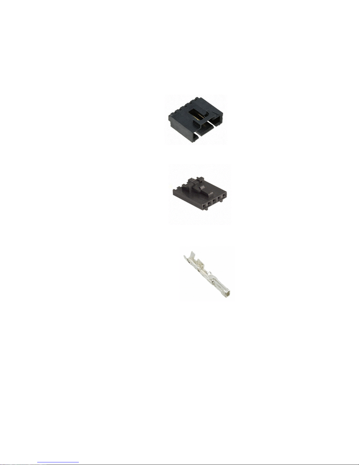
The iPort/USB 2 uses the following 1x5 2.54 mm (.100") pitch, 0.64 mm (.025")
2
square pin, header and plug assemblies for the I
2
C Header Receptacle
I
C Bus interface.
Molex C-Grid® SL™ 70553 Header
Molex Part # 70553-0004
2
I
C Plug Housing
Molex C-Grid® SL™ 70066 Crimp Housing
Molex C-Grid® SL™ 70058 Crimp Terminal
2
The following I
MCC Part # I2CMCL5 5-wire I
MCC Part # I2CMIC5-2 5-wire I
C Cables are available from MCC
2
C Mini Clip Lead Cable 0.3 m (1')
2
C Mini Interface Cable 0.6 m (2')
Molex Part # 50-57-9405
Molex Part # 16-02-0102
16
Page 22

Declaration of Conformity
FCC Statement
DECLARATION OF CONFORMITY WITH FCC RULES FOR ELECTROMAGNETIC
COMPATIBILITY
We, Micro Computer Control Corporation, of 83 Princeton Avenue #1D / PO Box 275,
Hopewell, New Jersey 08525 USA, declare under our sole responsibility that the product:
iPort/USB 2 (#MIIC-208)
to which this declaration relates:
CE Declaration of Conformity
We, Micro Computer Control Corporation, of 83 Princeton Avenue #1D / PO Box 275,
Hopewell, New Jersey 08525 USA, declare under our sole responsibility that the iPort/USB 2
(#MIIC-208), to which this declaration relates, is in conformity with General Emissions
Standard EN55022:2010 (CISPR22:2008) Class A, and General Immunity Standard EN 55024:
2010 (CISPR22:2010).
Test Laboratory Information:
MET Laboratories, Inc.
Test Report Number: EMC85413-EN
Test Report Date: April 13, 2015
Technical file held by: Micro Computer Control Corporation, 83 Princeton Avenue #1D / PO
Box 275, Hopewell, New Jersey 08525 USA, or its applicable authorized distributor or
representative
www.mcc-us.com
17
Page 23

www.mcc-us.com
18
 Loading...