

MCC 68AC353-102 MICROMAX Service Manual
T-348 Manual
OPERATION AND SERVICE
for
68AC353-102
MICROMAX
T-348
REV. 07/2012
© 2012 Mobile Climate Control

TABLE OF CONTENTS
SAFETY SUMMARY Safety-1...............................................................
DESCRIPTION 1-1....................................................................
1.1 INTRODUCTION 1-1.......................................................
1.2 CONFIGURATION IDENTIFICATION 1-1.....................................
1.3 OPTION DESCRIPTION 1-1.................................................
1.3.1 Condenser Cover (Skins) 1-1.............................................................
1.3.2 Condenser Electrical Kit 1-1..............................................................
1.3.3 Condenser Fan Kit 1-1..................................................................
1.3.4 Condenser Refrigeration Kit 1-1...........................................................
1.3.5 Evaporator Skins Kit 1-1................................................................
1.3.6 Evaporator Blower Kit 1-1...............................................................
1.3.7 Evaporator Connection Kit S/D 1-1.......................................................
1.3.8 Evaporator Connection Kit - Indash 1-1.....................................................
1.3.9 Evaporator Connection Kit (Heating) 1-1....................................................
1.3.10 Air Exchange Kit 1-2...................................................................
1.3.11 Controller Kit 1-2......................................................................
1.4 GENERAL DESCRIPTION 1-4...............................................
1.4.1 Compressor Assembly 1-4...............................................................
1.4.2 Discharge Check Valve 1-4...............................................................
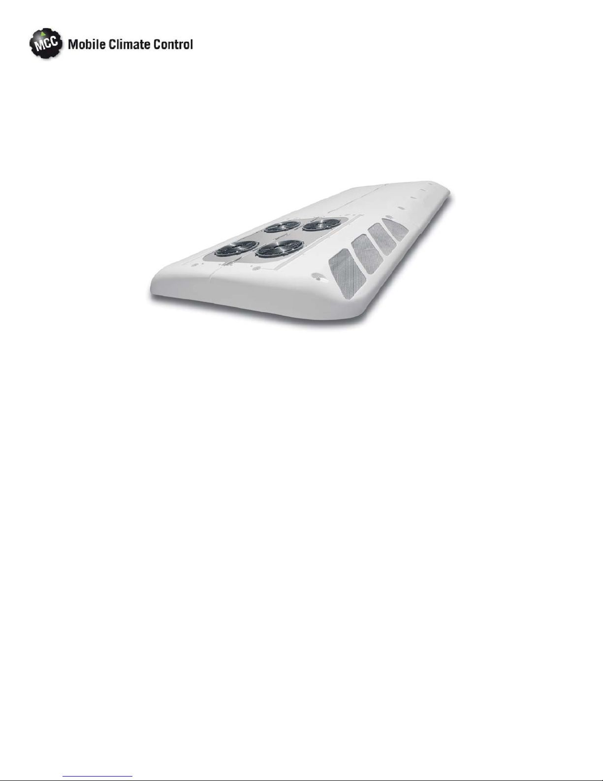
1.4.3 Rooftop Unit 1-5......................................................................
1.4.4 Condensing Section 1-6.................................................................
1.4.5 Evaporator Section 1-7..................................................................
1.4.6 Fresh Air System 1-7...................................................................
1.4.7 System Operating Controls And Components 1-8.............................................
1.5 REFRIGERATION SYSTEM COMPONEN T SPECIFICATIONS 1-8.................
1.6 ELECTRICAL SPECIFICATIONS - MOTORS 1-8................................
1.7 ELECTRICAL SPECIFICATIONS - SENSORS AND TRANSDUCERS 1-9............
1.8 SAFETY DEVICES 1-9......................................................
1.9 AIR FLOW 1-10.............................................................
1.10 AIR CONDITIONING REFRIGERATION CYCLE 1-11............................
1.11 HEATING CYCLE 1-13.......................................................
1.12 CONTROL PANEL WITH GR60 RELAY BOARD 1-14.............................
1.13 CONTROL PANEL 1-15......................................................
1.14 LOGIC BOARD 1-16.........................................................
1.15 RELAY BOARD - GR60, 24VDC 1-17............................................
1.15 RELAY BOARD - GR60, 24VDC (Continued) 1-18..................................
1.16 RELAY BOARD, 24VDC 1-19..................................................
1.17 LOGIC BOARD, DATA COMMUNICATIONS 1-20...............................
1.18 CONTROL PANEL (Diagnostic Module) 1-21......................................
OPERATION 2-1......................................................................
2.1 STARTING, STOPPING AND OPERATING INSTRUCTIONS 2-1..................
© 2012 Mobile Climate Control T-348 Rev. 07/2012
1

TABLE OF CONTENTS - Continued
2.1.1 Power to Logic Board 2-1................................................................
2.1.2 Starting 2-1...........................................................................
2.1.3 Self-Test and Diagnostics (Check for Errors and/or Alarms) 2-1..................................
2.1.4 Stopping 2-1..........................................................................
2.2 PRE-TRIP INSPECTION 2-2..................................................
2.3 MODES OF OPERATION 2-2................................................
2.3.1 Temperature Control 2-3................................................................
2.3.2 Cooling Mode 2-3......................................................................
2.3.3 Heating Mode 2-3......................................................................
2.3.4 Boost Pump 2-3.......................................................................
2.3.5 Vent Mode 2-3........................................................................
2.3.6 Compressor Unloader Control 2-3.........................................................
2.3.7 Evaporator Fan Speed Selection 2-4........................................................
2.3.8 Condenser Fan Control 2-4..............................................................
2.3.9 Compressor Clutch Control 2-4...........................................................
2.3.10 Liquid Line Solenoid Control 2-4..........................................................
2.3.11 Alarm Description 2-4..................................................................
2.3.12 Hour Meters 2-4.......................................................................
2.4 MICROPROCESSOR DIAGNOSTICS 2-4.......................................
2.4.1 Control 2-5...........................................................................
2.4.2 Diagnostic Mode 2-5...................................................................
2.4.3 System Parameters 2-5..................................................................
2.4.4 Test Mode 2-6........................................................................
TROUBLESHOOTING 3-1................................................................
3.1 SELF DIAGNOSTICS 3-1....................................................
3.2 SYSTEM ALARMS 3-1.......................................................
3.2.1 Alarm Codes 3-1.......................................................................
3.2.2 Activation 3-1.........................................................................
3.2.3 Alarm Queue 3-1......................................................................
3.2.4 Alarm Clear 3-1.......................................................................
3.2.5 Exit Alarm Queue 3-2..................................................................
3.3 TROUBLESHOOTING 3-2...................................................
3.3.1 Troubleshooting No CAN Communication 3-2.....................................
3.3.2 System Will Not Cool 3-5................................................................
3.3.3 System Runs But Has Insufficient Cooling 3-5................................................
3.3.4 Abnormal Pressures 3-5.................................................................
3.3.5 Abnormal Noise Or Vibrations 3-5.........................................................
3.3.6 Control System Malfunction 3-6...........................................................
3.3.7 No Evaporator Air Flow Or Restricted Air Flow 3-6...........................................
3.3.8 Expansion Valve Malfunction 3-6..........................................................
3.3.9 Heating Malfunction 3-6.................................................................
SERVICE 4-1........................................................................
4.1 MAINTENANCE SCHEDULE 4-1.............................................
© 2012 Mobile Climate Control T-348 Rev. 07/2012
2

TABLE OF CONTENTS - Continued
4.2 OPENING TOP COVER ( E VAPORATOR) 4-2...................................
4.3 REMOVING TOP COVER (CONDENSER) 4-2..................................
4.4 SUCTION AND DISCHARGE SERVICE VALVES 4-3............................
4.4.1 Installing R-134a Manifold Guage Set 4-3....................................................
4.5 PUMPING THE SYSTEM DOWN OR REMOVING THE REFRIGERANT CHARGE 4-4
4.5.1 System Pump Down For Low Side Repair 4-4................................................
4.5.2 Refrigerant Removal From An Inoperative Compressor. 4-5.....................................
4.5.3 Pump Down An Operable Compressor For Repair 4-7.........................................
4.5.4. Removing Entire System Charge 4-7.......................................................
4.6 REFRIGERANT LEAK CHECK 4-7............................................
4.7 EVACUATION AND DEHYDRATION 4-8.....................................
4.7.1 General 4-8...........................................................................
4.7.2 Preparation 4-8........................................................................
4.7.3 Procedure for Evacuation and Dehydrating System (One Time Evacuation) 4-8......................
4.7.4 Procedure for Evacuation and Dehydrating System (Triple Evacuation) 4-8.........................
4.8 ADDING REFRIGERANT TO SYSTEM 4-8.....................................
4.8.1 Checking Refrigerant Charge 4-8..........................................................
4.8.2 Adding Full Charge 4-9.................................................................
4.8.3 Adding Partial Charge 4-9................................................................
4.9 CHECKING FOR NONCONDENSIBLES 4-9...................................
4.10 CHECKING AND REPLACING HIGH OR LOW PRESSURE SWITCH 4-9...........
4.11 FILTER-DRIER 4-10.........................................................
4.11.1 To Check Filter-Drier 4-10.................................................................
4.11.2 To Replace Filter-Drier 4-10..............................................................
4.12 SERVICING THE LIQUID LINE SOLENOID VALVE 4-11.........................
4.12.1 Coil Replacement 4-11...................................................................
4.12.2 Internal Part Replacement 4-11............................................................
4.12.3 Replace Entire Valve 4-11..................................................................
4.13 THERMOSTATIC EXPANSION VALVE 4-12....................................
4.13.1 Valve Replacement 4-12..................................................................
4.13.2 Superheat Measurement 4-12..............................................................
4.14 REPLACING EVAPORATOR RETURN AIR FILTERS 4-13.........................
4.15 COMPRESSOR MAINTENANCE 4-13..........................................
4.15.1 Removing the Compressor 4-13............................................................
4.15.2 Transferring Compressor Clutch 4-14........................................................
4.15.2 Transferring Compressor Clutch (Continued) 4-15..............................................
4.15.3 Shim-less Compressor Clutch 4-15..........................................................
4.15.4 Compressor Oil Level 4-16................................................................
4.15.5 Checking Unloader Operation 4-16.........................................................
4.16 TEMPERATURE SENSOR CHECKOUT 4-17.....................................
4.17 PRESSURE TRANSDUCER CHECKOUT 4-17....................................
© 2012 Mobile Climate Control T-348 Rev. 07/2012
3

TABLE OF CONTENTS - Continued
4.18 REPLACING SENSORS AND TRANSDUCERS 4-18...............................
4.19 LOGIC BOARD REPLACEMENT 4-19..........................................
ELECTRICAL 5-1......................................................................
5-1 INTRODUCTION 5-1.........................................................
LIST OF FIGURES
Figure 1-1 System Component Identification 1-4..........................................
Figure 1-2 Rooftop Unit Components 1-5...............................................
Figure 1-3 Condensing Section Components 1-6..........................................
Figure 1-4 Evaporator Section Components 1-7...........................................
Figure 1-5 System Air Flow 1-10........................................................
Figure 1-6 Refrigerant Flow Diagram 1-12................................................
Figure 1-7 Heat Flow Diagram 1-13.....................................................
Figure 1-8 Control Panel 1-14..........................................................
Figure 1-9 Control Panel 1-15..........................................................
Figure 1-10 Logic Board 1-16..........................................................
Figure 1-11. Relay Board - GR60 1-17...................................................
Figure 1-11. Relay Board - GR60 (Continued) 1-18.........................................
Figure 1-12. Relay Board 1-19..........................................................
Figure 1-13 Logic Board, Data Communications 1-20.......................................
Figure 1-14 Micromate Control Panel 1-21................................................
Figure 2-1 Capacity Control Diagram 2-2................................................
Figure 4-1 Opening Top Cover (Evaporator) 4-2..........................................
Figure 4-2 Condenser Cover Removal 4-2...............................................
Figure 4-3 Suction or Discharge Service Valve 4-3.........................................
Figure 4-4 Manifold Gauge Set (R-134a) 4-4..............................................
Figure 4-5 Compressor Service Connections 4-5..........................................
Figure 4-6 Service Con n ections 4-6.....................................................
Figure 4-7 Checking High Pressure Switch 4-10............................................
Figure 4-8 Filter-Drier Removal 4-10....................................................
Figure 4-9 Liquid Line Solenoid Valve 4-11...............................................
Figure 4-10 Thermostatic Expansion Valve 4-12...........................................
Figure 4-11 Thermostatic Expansion Valve Bulb and Thermocouple 4-12........................
Figure 4-12 Compressor 4-14..........................................................
Figure 4-13 Removing Bypass Piston Plug 4-14............................................
Figure 4-14 Compressor Clutch 4-14....................................................
Figure 4-15 Transducer Terminal Location 4-17............................................
Figure 5-1. Wiring Schematic - Legend (PM Motors) - 68AC353-102, 102-4, 102-5 5-2.............
Figure 5-2. Wiring Schematic - Control Circuit (PM Motors) - 68AC353-102, 102-4, 102-5 5-3.......
© 2012 Mobile Climate Control T-348 Rev. 07/2012
4

Figure 5-3. Wiring Schematic - Power Circuit (PM Motors) - 68AC353-102, 102-4, 102-5 5-4........
Figure 5-4. Wiring Schematic - Legend (Brushless Motors) (CAN) - 68AC353-102-1, 102-3, 102-6 5-5.
Figure 5-5. Wiring Schematic - Control Circuit (Brushless Motors) (CAN) - 68AC353-102-1, 102-3, 102-6 .
5-6..............................................................................
Figure 5-6. Wiring Schematic - Power Circuit (Brushless Motors) (CAN) - 68AC353-102-1, 102-3, 102-6 . .
5-7..............................................................................
Figure 5-7. Wiring Schematic - Condenser Circuit (Brushless Motors) (CAN) - 68AC353-102-1, 102-3, 102-6
5-8..............................................................................
Figure 5-8. Wiring Schematic - Evaporator Circuit (Brushless Motors) (CAN) - 68AC353-102-1, 102-3, 102-6
5-9..............................................................................
Figure 5-9. Wiring Schematic - Legend (Brushless Motors) - 68AC353-102-2 & 102-7 5-10...........
Figure 5-10. Wiring Schematic - Control Circuit (Brushless Motors) - 68AC353-102-2 & 102-7 5-11....
Figure 5-11. Wiring Schematic - Control Board Power Circuit (Brushless Motors) - 68AC353-102-2 & 102-7
5-12..............................................................................
Figure 5-12. Wiring Schematic - Condenser Motor Power Circuit (Brushless Motors) - 68AC353-102-2 & 102-7
5-13..............................................................................
Figure5-13. WiringSchematic - EvaporatorMotor PowerCircuit (Brushless Motors) - 68AC353-102-2& 102-7
5-14..............................................................................
LIST OF TABLES
Table 1-1 Option Legend 1-3..........................................................
Table 1-2 Option Table 1-3............................................................
Table 1-3 Additional Support Manuals 1-4................................................
Table 2-1. Unloader UV1 Relay 2-4......................................................
Table 2-2. Unloader UV2 Relay 2-4......................................................
Table 2-3 Evaporator Fan Speed Relay Operation 2-4.......................................
Table 2-4. Controller Test List 2-6......................................................
Table 2-5. Parameter Codes 2-7........................................................
Table 3-1 Error Codes 3-1............................................................
Table 3-2 Alarm Codes 3-3............................................................
Table 3-3. General System Troubleshooting Procedures 3-5...................................
Table 4-1 Temperature Sensor Resistance 4-17..............................................
Table 4-2 Pressure Transducer Voltage 4-18................................................
Table 4-3 Logic Board Configuration 4-19.................................................
Table 4-4 R-134a Temperature - Pressure Chart 4-20.........................................
© 2012 Mobile Climate Control T-348 Rev. 07/2012
5
SAFETY SUMMARY
GENERAL SAFETY NOTICES
The following general safety notices supplement the specific warnings and cautions appearing elsewhere in this
manual. They are recommended precautions that must be understood and applied during operation and
maintenance of the equipment covered herein. A listing of the specific warnings and cautions appearing
elsewhere in the manual follows the general safety notices.
FIRST AID
An injury, no matter how slight, should never go unattended. Always obtain first aid or medical attention
immediately.
OPERATING PRECAUTIONS
Always wear safety glasses.
Keep hands, clothing and tools clear of the evaporator and condenser fans.
No work shouldbe performed on the unit until all start-stopswitches are placedin the OFF position,and power
supply is disconnected.
Always work in pairs. Never work on the equipment alone.
In case of severe vibration or unusual noise, stop the unit and investigate.
MAINTENANCE PRECAUTIONS
Beware of unannounced starting of the evaporator and condenser fans. Do not open the unit cover before
turning power off.
Be sure power is turned off before working on motors, controllers, solenoid valves and electrical controls. Tag
circuit breaker and p o wer supply to prevent accidental energizing of circuit.
Do not bypass any electrical safety devices, e.g. bridging an overload, or using any sort of jumper wires.
Problems with the system should be diagnosed, and any necessary repairs performed by qualified service
personnel.
When performing any arc welding on the unit, disconnect all wire harness connectors from the modules in the
control box. Do not remove wire harness from the modules unless you are grounded to the unit frame with a
static-safe wrist strap.
In case of electrical fire, open circuit switch and extinguish with CO2(never use water).
UNIT HAZARD LABEL IDENTIFICATION
To help identify the hazard labels on the unit and explain the level of awareness each on e carries, explanations
with appropriate consequences are provided below:
Indicates an immediate h azard which WILL result in severe personal injury or death.
Indicates hazards or unsafe conditions which COULD result in severe personal injury or death.
Indicates potential hazards or unsafe practices which COULD result in minor personal injury, product or
property damage.
© 2012 Mobile Climate Control T-348 Rev. 07/2012
DANGER
WARNING
CAUTION
Safety-1
SPECIFIC WARNING AND CAUTION STATEMENTS
The statements listed below are applicable to the refrigeration unit and appear elsewhere in this manual. These recommended
precautions must be understood and applied during operation and maintenance of the equipment covered herein.
SPECIFIC WARNINGS AND CAUTIONS
WARNING
Be sure to observe warnings listed in the safety summary in the front of this manual before
performing maintenance on the hvac system
WARNING
Read the entire procedurebefore beginning work. Park the coach on a level surface, with park
ing brake applied. Turn main electrical disconnect switch to the off position.
WARNING
Do not use a nitrogen cylinder without a pressure regulator
WARNING
Do not use oxygen in or near a refrigeration system as an explosion may occur.
WARNING
The filter-drier may contain liquid refrigerant.Slowly loosen the ORS hex nuts to avoid refriger
ant contact with exposed skin or eyes.
WARNING
Battery disconnect should be off.
WARNING
Extreme care must be taken to ensure that all the refrigerant has been removed from the com
pressor crankcase or the resultant pressure will forcibly discharge compressor oil.
Do not under any circumstances attempt to service the microprocessor. Should a problem de
velop with the microprocessor, replace it.
© 2012 Mobile Climate Control T-348 Rev. 07/2012
CAUTION
Safety-2
CAUTION
To prevent trapping liquid refrigerant in the manifold gauge set be sure set is brought to suc
tion pressure before disconnecting.
CAUTION
Use care when checking/manipulating wires/plugs attached to the Logic Board. Damage to
the board or wiring harness can occur.
© 2012 Mobile Climate Control T-348 Rev. 07/2012
Safety-3

SECTION 1
DESCRIPTION
1.1 INTRODUCTION
This manual contains Operating Instructions,
Service Instructions and Electrical Data for the
Model 68AC353 Air Conditioning and Heating
equipment furnished by Mobile Climate Control as
shown in Table 1-1 and Table 1-2. Additional
support manuals are referenced in Table 1-3.
The Mobile Climate Control model 68AC series
units are of lightweight frame construction,designed
to be installed on the vehicle roof.
Model 68AC353 systems consists of a condensing
section, evaporator section and an engine
compartment mou n ted compressor. To complete
the system, the air conditioning and heating
equipment interfaces with electrical cabling,
refrigerant piping, engine coolant piping (for
heating), duct work and other components
furnished by the bus manufacturer. See Figure 1-1.
Operation of the units is controlled automatically by
a microprocessor based Micromax Controller which
maintains the vehicle's interior temperature at the
desired set point.
1.2 CONFIGURATION IDENTIFICATION
Unit identification information is provided on a plate
located inside the condenser and evaporator
sections. The plate provides the unit model number,
the unit serial number and the unit parts
identification number (PID). The model number
identifies the overall unit configuration while the
PID provides information on specific optional
equipment and differences in detailed parts.
The following paragraphs provide descriptions of
the options provided. A tabular listing of unit model
numbers and PID numbers, used to assist the reader
in identifying the equipment supplied is provided in
Table 1-1 and Table 1-2.
1.3 OPTION DESCRIPTION
Various options may be factory or field equipped to
the base unit. These options are listed in the tables
and described in the following subparagraphs.
1.3.1 Condenser Cover (Skins)
The condenser section may be fitted with one of two
different cover assemblies dependent upon the
curvature of the bus roof. The assemblies available
are identified as the 10 M radius cover and the 6.5 M
radius cover.
1.3.2 Condenser Electrical Kit
The 68AC353 con denser kits are wired for either 24
Volt permanent magnet motors or 24 Volt brushless
motors.
1.3.3 Condenser Fan Kit
The 68AC353 condenser kits are available with either
4 or 6 fans, with either permanent magnet or
brushless motors.
1.3.4 Condenser Refrigeration Kit
The 68AC353 condensers are all fitted with a
condenser coil, a receiver with sight glasses and
fusible plug, a charge isolation valve and
interconnecting tubing.
1.3.5 Evaporator Skins Kit
The evaporator section may be fitted with one of two
different cover assemblies dependent upon the
curvature of the bus roof. The assemblies available
are identified as the 10 M radius cover and the 6.5 M
radius cover.
1.3.6 Evaporator Blower Kit
The 68AC353 evaporator kits are available with
either 4 or 6 blowers, with either permanent magnet
or brushless motors.
1.3.7 Evaporator Connection Kit S/D
The evaporator units are assembled to allow
orientation of the connections for different
mounting arrangements and may be supplied with
various refrigerant piping layouts for specific
applications.
1.3.8 Evaporator Connection Kit - Indash
The evaporator units are assembled to allow
connections for various refrigerant piping layouts for
remote evaporators.
1.3.9 Evaporator Connection Kit (Heating)
The evaporator units are assembled to allow
orientation of the connections for different
mounting arrangements and may be supplied with
various engine coolant piping layouts for specific
heating applications.
© 2012 Mobile Climate Control T-348 Rev. 07/2012
1--1

1.3.10 Air Exchange Kit
1.3.11 Controller Kit
The unit will be fitted with a fresh air exchange
assembly or an air exchange blank off plate. Fresh air
exchange assemblies may be of the 25% or 50 %
opening.
The Micromax Controller operates the system
through one of two relay boards and may be
interrogated through the optional CAN +/- Data
Communication Link.
© 2012 Mobile Climate Control T-348 Rev. 07/2012
1--2
OPTION DESCRIPTION
Condenser Skins Kit
1 Standard Cover (R10M)
2 Cover (R6.5M)
Condenser Electrical Kit
1 Condenser Electrical Kit
2 Condenser Electrical Kit / Brushless
Condenser Fan Kit
1 24 Volt With 4 Brushless Motors
2 24 Volt With 4 PM Motors
3 24 Volt With 6 Brushless Motors
4 24 Volt With 6 PM Motors
Evaporator Skins Kit
1 Standard Cover (R10M)
2 Cover (R6.5M)
Evaporator Blower Kit
1 24 Volt With 6 Brushless Motors
2 24 Volt With 4 Brushless Motors
3 24 Volt With 6 PM Motors
Evaporator Refrigeration Kit
1 4 Row Coil Refrigeration Kit
2 5 Row Coil Refrigeration Kit
3 3 Row Coil Refrigeration Kit
Table 1-1 Option Legend
OPTION DESCRIPTION
Evaporator Connection Kit S/D
1 Left - ORS
2 Right - ORS
3
Evaporator Connection Kit - Indash
1 Right
2 Left
Air Exchange Kit
1 0 to 50%
2 None
3 0 to 25%
Controller Kit
1 Micromax With GR60 Relay Board (right)
2
3 Micromax Relay Board
4
5 Micromax With GR60 Relay Board (left)
Left - ORS With Out Front Box
Connection
Micromax Relay Board With CAN DATA
(right)
Micromax Relay Board With CAN DATA
(left)
Table 1-2 Option Table
MODEL
68AC353
AC353C
PID Condenser
AC353E
PID Evaporator
Skins Kit
Condenser
Condenser
Electrical Kit
Fan Kit
Condenser
Evaporator
Skins Kit
Evaporator
Blower Kit
Evaporator
S/D
Connection Kit
Evaporator
Connection Kit
In Dash
Evaporator
Refrigeration Kit
-102 00001 00001 1 1 2 1 3 1 1 1 3 1
-102-1 00002 00002 1 2 1 1 1 1 1 1 3 2
-102-2 00003 00003 1 2 3 1 1 2 2 1 3 3
-102-3 00004 00004 1 2 3 1 1 2 2 1 3 4
-102-4 00005 00005 1 1 2 1 3 2 2 1 3 5
-102-5 00006 00006 1 1 4 1 3 2 2 1 3 5
-102-6 00007 00007 1 2 1 1 1 2 2 1 3 4
-102-7 00008 00008 1 2 1 1 1 2 2 1 3 3
Kit
Air Exchange
Controller Kit
© 2012 Mobile Climate Control T-348 Rev. 07/2012
1--3
Table 1-3 Additional Support Manuals
MANUAL/FORM NUMBER EQUIPMENT COVERED TYPE OF MANUAL
T-348PL 68AC353 Parts List
62-10699 Micromate Diagnostic Tool (Card)
6
4
3
2
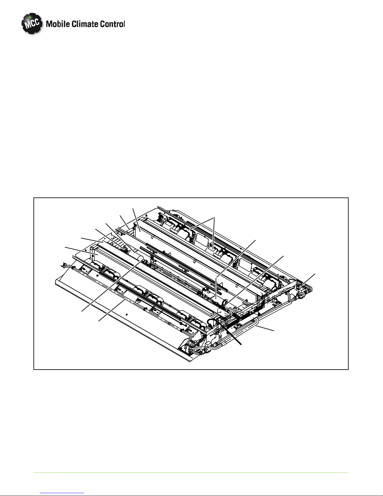
1
1. Compressor
2. Discharge Check Valve
3. Refrigerant Lines
4. Compressor Harness
5. Electronics Boards - Power Relay
6. Liquid Line Solenoid
7. AC353 (Rooftop) See Figure 1-2
5
7
11
10
13
8. Main Harness
9. Driver Control
10. Power Harness
11. Main Circuit Breaker
12. Battery
13. Alternator
12
8
9
Dash--Air
Option
1.4 GENERAL DESCRIPTION
1.4.1 Compressor Assembly
The compressor assembly is mounted in the engine
compartment (see Figure 1-1) and includes the
refrigerant compressor, clutch assembly, suction and
discharge service valves, high pressure switch, low
pressure switch, suction and discharge servicing
(charging) ports and electric solenoid unloaders.
The compressor raises the pressure and temperature
of the refrigerant and forces it into the condenser
tubes. The clutch assembly provides a means of belt
driving the compressor by the bus engine. The
suction and discharge service valves enable servicing
of the compressor. Suction and discharge servicing
(charging) ports mounted on the service valves
enable connection of charging h o ses for servicing of
the compressor, as well as other parts of the
© 2012 Mobile Climate Control T-348 Rev. 07/2012
Figure 1-1 System Component Identification
refrigerant circuit. The high pressure switch cont acts
open on a pressure rise to shut down the system
when abnormally high refrigerant pressures occur.
The electric unloaders provide a means of
controlling compressor capacity, which enables
control of t emperature inside the bus. For more
detailed information on the 05G compressor, refer
to the Operation and Service Manual number
62-02756.
1.4.2 Discharge Check Valve
A check valve is located in the discharge line close to
the compressor. (see Figure 1-1) The discharge
check valve is a spring loaded, normally closed valve
that opens with the flow of refrigerant from the
compressor. When the compressor clutch is
disengaged, the discharge check valve will close,
1--4
preventing the flow of high pressure liquid from the
condenser back into the compressor.
1.4.3 Rooftop Unit
The Rooftop unit (see Figure 1-2) is comprised of
the condensing section, evaporator section,
Micromax electronics, and the Fresh Air System. All
components are accessible by lifting the condenser
and evaporator top covers. Descriptions of the
systems are provided in the following sub
paragraphs.
1
3
4
6
5
2
1. Top Cover, Condenser
2. Top Cover, Evaporator
3. Condenser Section (See Figure 1-3)
© 2012 Mobile Climate Control T-348 Rev. 07/2012
4. Evaporator Section (See Figure 1-4)
5. Hinge, Evaporator Cover
6. Condenser Fan Grille
Figure 1-2 Rooftop Unit Components
1--5
1.4.4 Condensing Section
The condensing section (Figure 1-3) includes the
cover, left and right condenser coils, fan and motor
assemblies, receiver, service valves and an ambient
temperature sensor..
High pressure high temperature refrigerant gas from
the compressor passes thru the shipping shut-off
valves to the condenser coils.
The condenser coils provide heat transfer surface for
condensing refrigerant gas at a high temperature and
pressure. The condenser fans circulate ambient air
across the outside of the condenser tubes at a
temperature lower than refrigerant circulating inside
6
the tubes; t his results in condensation of the
refrigerant into a liquid.
The receiver collects and stores liquid refrigerant.
The receiver is also fitted with a fusible plug which
protects the system from unsafe high pressure
conditions and liquid level sight glasses to determine
proper refrigerant liquid level.
The liquid refrigerant then passes thru the liquid line
charge isolation valve to the evaporator.
An ambient temperature sensor measures ambient
temperature and sends an electrical signal to the
controller.
PID
Model/Serial
Number Tag
2
1. Coil Assembly
2. Receiver
3. Charge Isolation Valve
4. Discharge Line.
7
4
1
5. Liquid Line
6. Condenser Fan and Motor Assembly
7. Ambient Temperature Sensor
8. Shipping Shut-off Valves
8
5
3
© 2012 Mobile Climate Control T-348 Rev. 07/2012
Figure 1-3 Condensing Section Components
1--6
1.4.5 Evaporator Section
The evaporator section (Figure 1-4) includes the
evaporator coils, six blower and motor assemblies,
evaporator coil assemblies, heater coil assemblies,
filter drier, a thermostatic expansion valve, liquid line
solenoid, service valves and condensate drain
connections.
The evaporator coils provide heat transfer surface
for transferring heat from air circulating over the
outside coil area to the refrigerant circulating inside
the tubes; thus providing cooling. The heating coils
provide heat transfer surface for transferring heat
from engine coolant water circulating inside the
tubes to air circulating over the outside surface of the
tubes, thus providing heating. The fans circulate the
air over th e coils. The air filters remove dirt particles
from the air before it passes over the coils. The
3
13
5
10
filter-drier removes moisture and debris from the
liquid refrigerant before it enters the thermostatic
expansion valve in the evaporator assembly. Service
valves enable isolation of the filter-drier for service.
The thermostatic expansion valve meters flow of
refrigerant entering the evaporator coils. The liquid
line solenoid valve closes when system is shut down
to prevent flooding of the evaporator coils with
liquid refrigerant.
A heat valve controls the flow of engine coolant
water t o th e heating coils upon receipt of a signal
from the controller. The condensate drain
connections provide a means for connecting tubing
for disposing of condensate collected on the
evaporator coils during cooling operation.
6
1
2
9
8
1. Evaporator Coil Assembly
2. Heat Coil
3. Evaporator Return Air Filter
4. Expansion Valve
5. Filter Drier
6. Blower & Motor Assembly
7. Suction Line
12
4
11
7
PID
Model/Serial
Number Tag
8. Discharge Line
9. Service Valve
10. Liquid Line Solenoid
11. Heat Line Connection
12. Control Panel
13. Fresh Air Damper
1.4.6 Fresh Air System
The Fresh Air System consists of a damper and
damper operator. The damper operator may be
© 2012 Mobile Climate Control T-348 Rev. 07/2012
Figure 1-4 Evaporator Section Components
controlled by the driver, if a switch is provided. In the
automatic mode, it is controlled by the Micromax to
1--7
open and close the damper to allowaddition of fresh
air into the air entering the evaporator coil. For
additional information on air flow,refer to paragraph
1.9.
1.4.7 System Operating Controls And Components
The system is operated by a Mobile Climate Control
Micromax microprocessor controller which consist
of a relay board (Figure 1-11), logic board
(Figure 1-10), and manual operator switches. The
manual operating switches are located on the drivers
control and may consist of a single OEM supplied
ON/OFFswitch, additionalOEM supplied switches
or a Mobile Climate Control supplied Micromate
control panel (Figure 1-14). The logic board
regulates the operational cycles of the system b y
energizing or de-energizing relays on the relay board
in response to deviations in interior temperature.
Modes of operation include Cooling, Heat and Vent.
On systems fitted with only an ON/OFF switch and
on systems with the Micromate set in the AUTO
mode, the logic board will cycle the system between
the operating modes as required to maintain desired
set point temperature.
In the vent mode the evaporator fans are operated to
circulate air in the bus interior.
In the heat mode the heat valve is opened to allow a
flow of engine coolant through the heat coils of the
evaporator coil. The evaporator fans operate to
circulate air over the evaporator coil in the same
manner as the vent mode.
In the cooling mode the compressor is energized
while the evaporator and condenser fans are
operated to provide refrigeration as required. The
compressor is fitted with cylinder unloaders to
match compressor capacity to the bus requirements.
Once interior temperature reaches the desired set
point, the system may operate in the clutch cycle or
reheat mode. A controller programmed for clutch
cycle will de-energize t h e compressor clutch and
allow the system to operate in the vent mode until
further cooling is required. A controller
programmed for reheat will maintain compressor
operation and open the heat valve to allow reheating
of the return air. In the reheat mode interior
temperature is maintained at the desired set point
while additional dehumidification takes place.
Controls may also be provided to allow manual
operation of the evaporatorfans in low or high speed
and manual control of the fresh air damper in the
open or closed position.
1.5 REFRIGERATION SYSTEM COMPONENT SPECIFICATIONS
a. Refrigerant Charge
R-134a15.8 Lb (7.17 kg)
b. Compressor
UNIT MODEL
Compressor 05G
No of Cylinders 6
Weight - Dry
W/Clutch
Oil Charge 5.5 pints
Oil Level: Level in sight glass betweenMin.-Max marks on
compressor crankcase (curbside)
Approved Compressor Oils - R-134a:
Castrol: Icematic SW68C
Mobil: EAL Arctic 68
ICI: Emkarate RL68H
c. Thermostatic Expansion Valve:
Superheat Setting: 12 ±2°F(6.7±1°C)
d. High Pressure Switch (HPS):
Opens at: 350 ±10 psig (23.81 ±0.68bar)
Closes at: 250 ±10 psig (13.61 ±0.68bar)
e. Low Pressure Switch (LPS)
Opens at: 6 ±3psig (0.41 ±0.20 bar)
Closes at: 25 ±3psig(1.7±0.20 bar)
f. Water Temperature Switch (WTS)
Bus manufacturer supplied - suggested close on tempera
ture rise at 105°F(41°C).
AC353
145 lbs
(65.77 kg)
(2.6 liters)
1.6 ELECTRICAL SPECIFICATIONS - MOTORS
a. Evaporator Fan Motor
Evaporator Motor
Horsepower (kW) 0.53/0.39 0.4/0.3
Full Load Amps (FLA) 15.2 11.0
Operating Speed (RPM)
Bearing Lubrication Factory Lubricated
b. Condenser Fan Motor
Condenser Motor
Horsepower (kW) 0.24/0.18 0.25/0.20
Full Load Amps (FLA) 7.0 7.2
Operating Speed (RPM)
Bearing Lubrication Factory Lubricated
Brushless
3830 3013
(additional grease not required)
Brushless
2840 1900
(additional grease not required)
Permanent
Magnet
24 VDC
Permanent
Magnet
24 VDC
© 2012 Mobile Climate Control T-348 Rev. 07/2012
1--8

1.7 ELECTRICAL SPECIFICATIONS - SENSORS AND
TRANSDUCERS
a. Suction and Discharge Pressure Transducer
Supply Voltage: 4.5 to 5.5 vdc (5 vdc nominal)
Supply current: 8 mA maximum
Output Range: 8K ohms minimum
Input Range: -6.7 to 450 psig (-0.46 to 30.62 bar)
b. Temperature Sensors
Input Range: -52.6 to 158°F(-47to70°C)
Output: NTC 10K ohms at 77°F(25°C)
1.8 SAFETY DEVICES
System components are protected from damage
caused by unsafe operating conditions with safety
devices. Safety devices with Mobile Climate Control
supplied equipment include high pressure switch
(HPS), low pressure switch (LPS), circuit breakers
and fuses.
a. Pressure Switches
High Pressure Switch (HPS)
During the A/C mode, compressor operation will
automatically stop if the HPS switch contacts open
due to an unsafe operating condition. Opening HPS
contacts de-energizes the compressor clutch
shutting down the compressor. The high pressure
switch (HPS) is installed in the center head of the
compressor.
Low Pressure Switch (LPS)
The low pressure switch is installed in the
compressor and opens on a pressure drop to shut
down the system when a low pressure condition
occurs. In addition, if the microprocessor monitors a
pressure less than 10 psig (0.68 bar)by the suction
pressure transducer mounted in the evaporator
section, the system will be shut down for at least one
minute.
b. Fuses and Circuit Breakers
The system is protected against high current b y an
OEM supplied 125 amp fuse or circuit breaker.
Independent fuses or circuit breakers protect each
evaporator blower motor and condenser motor
assembly. 5 amp fuses p ro t ect each relay board
output, 10 amp fuses protect ignition circuit output.
c. Ambient Lockout
The ambient temp erature sensor located in the
condenser section measures the condenser inlet air
temperature. When the temperature has fallen below
the cut out set point the compressor is locked out
until the temperature rises above the cut in setting.
The set points willbe programmed to cut out at 45°F
〈7.2°C) and cut in at 50°F 〈10°C). This setting
protects the compressor from damage caused by
operation at low pressures.
d. Water Temperature Switch (WTS)
When the the engine coolant temperature has fallen
below the cut out set point, the evaporator fans are
locked out until the temperature rises above the cut
in set point. The set point willbe programmed to cut
in at 105°F(41°C).
© 2012 Mobile Climate Control T-348 Rev. 07/2012
1--9
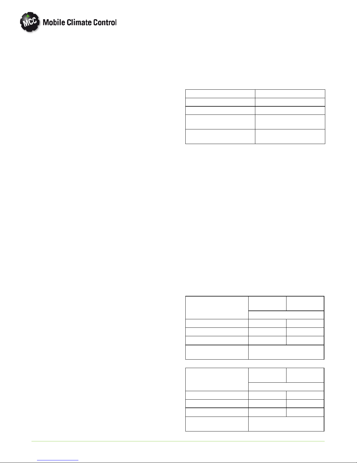
1.9 AIR FLOW
The paths for ambientair through the condenserand
coach air through the evaporator are illustrated in
Figure 1-5.
From Ambient
Through Condenser
EVAPORA T OR COIL
HEATER COIL HEATER COIL
COACH RETURN
AIR FILTER
COIL RETURN
AIR FILTERS
FRESH AIR
EVAPORA T OR COIL
EVAPORATOR
Return To Ambient
Through Fan
Through Fan
CONDENSER
Figure 1-5 System Air Flow
From Ambient
Through Condenser
© 2012 Mobile Climate Control T-348 Rev. 07/2012
1--10

1.10 AIR CONDITIONING REFRIGERATION CYCLE
When air conditioning (cooling) is selected by the
controller, the unit operates as a vapor compression
system using R-134a as the refrigerant (See
Figure 1-6). The main components of the system are
the reciprocating compressor, air-cooled condenser
coils, receiver, filter-drier, th ermo static expansion
valve, liquid line solenoid valve and evaporator coils.
The compressor raises the pressure and the
temperature of the refrigerant and forces it into th e
condenser tubes. The condenser fan circulates
surrounding air (which is at a temperature lower than
the refrigerant) over the outside of the condenser
tubes. Heat transfer is established from the
refrigerant (inside the tubes) to the condenser air
(flowing over the tubes). The condenser tubes have
fins designed to improve the transfer of heat from
the refrigerant gas to the air; this removal of heat
causes the refrigerant to liquefy, thus liquid
refrigerant leaves the condenser and flows to the
receiver.
The receiver serves as a liquid refrigerant reservoir so
that a constant supply of liquid is available to the
evaporators as needed and acts as a storage space
when p u m ping down the system. The receiver is
equipped with two sight glasses to observe
refrigerant charge level.
The refrigerant leaves the receiver and passes
through the charge isolation valve to the liquid line
solenoid valve. From the liquid line solenoid valve
the refrigerant enters the filter-drier where an
absorbent keeps the refrigerant clean and dry.
From the filter-drier, the liquid refrigerant then flows
through the liquid line service valve to the
thermostatic expansion valve. The liquid line is
equipped with a sight glass to observe the refrigerant
for restricted flow. The thermostatic expansionvalve
reduces pressure and temperature of the liquid and
meters the flow of liquid refrigerant to the
evaporator to obtain maximum use of the
evaporator heat transfer surface.
The low pressure, low temperature liquid that flows
into the evaporator tubes is colder than the air that is
circulated over the evaporator tubes by the
evaporatorfans. Heat transfer isestablishedfrom the
evaporator air (flowing over the tubes) to the
refrigerant (flowing inside the tubes). The
evaporator tubes have aluminum fins to increase
heat transfer from the air to the refrigerant;therefore
the cooler air is circulated to the interior of the bus.
Liquid line solenoid valve closes during shut do wn to
prevent refrigerant flow.
The transfer of heat from the air to the low
temperature liquid refrigerant in the evaporator
causes the liquid to vaporize. This low temperature,
low pressure vapor passes through the suction line
and returns to the compressor where the cycle
repeats.
© 2012 Mobile Climate Control T-348 Rev. 07/2012
1--11
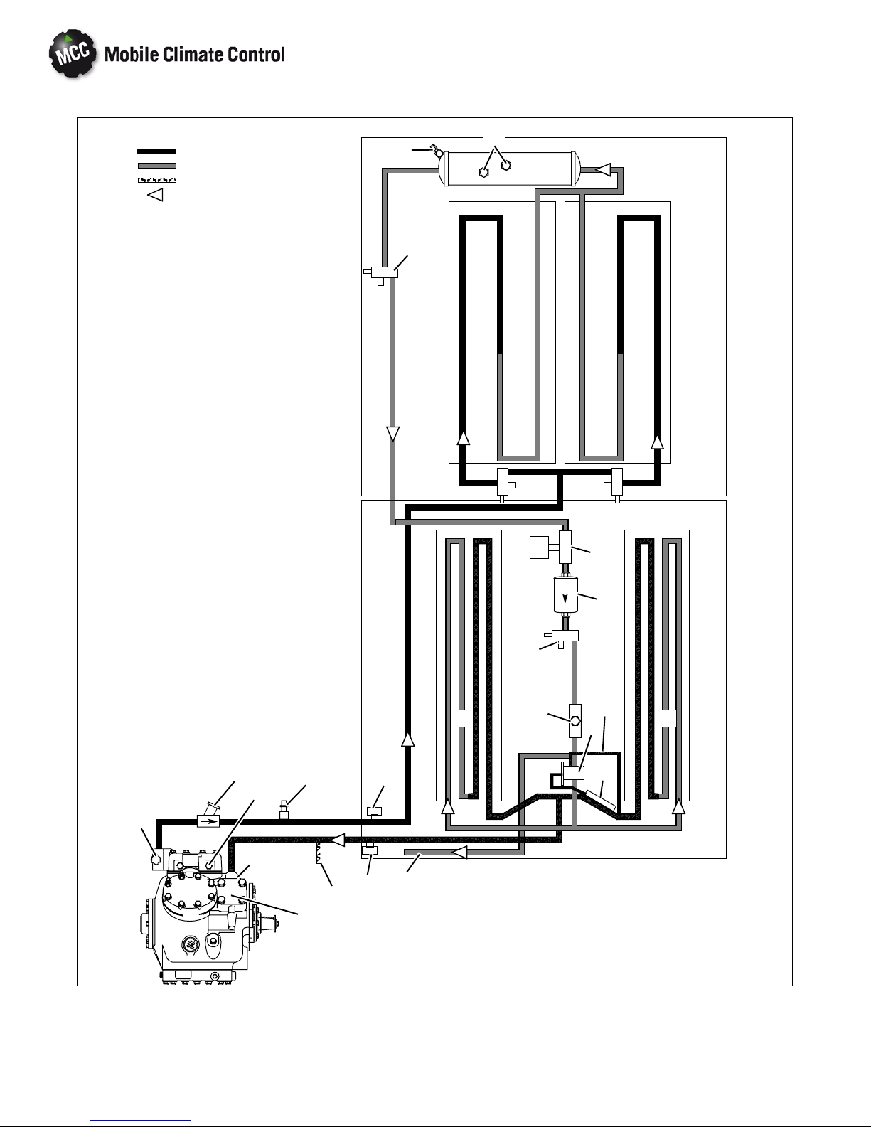
Legend
Discharge
Liquid
Suction
Refrigerant Flow
1. Discharge Service Valve
2. Discharge Check Valve
3. Service Port, Discharge
4. High Pressure Switch
5. Discharge Pressure Transducer
6. Low Pressure Switch (Crankcase)
7. Dash Air Liquid Line (Option)
8. Suction Service Valve/Port
9. Dash Air Suction Tee (Option)
10. Suction Pressure Transducer
11. Evaporator Coil
12. Thermal Expansion Valve (TXV)
13. TXV Bulb
14. TXV Equalizer Line
15. Liquid Line Solenoid Valve
16. Filter Drier
17. Liquid Line Service Valve
18. Liquid Line Sight Glass
19. Shipping Shut-off Valves
20. Condenser Coil
21. Receiver
22. Refrigerant Sight Glass
23. Fusible Plug
24. Charge Isolation Valve
23
24
22
20
19
17
CONDENSER
21
20
19
EVAPORATOR
15
16
2
4
1
6
© 2012 Mobile Climate Control T-348 Rev. 07/2012
11 11
10
5
7
3
9
8
Figure 1-6 Refrigerant Flow Diagram
1--12
18
14
12
13
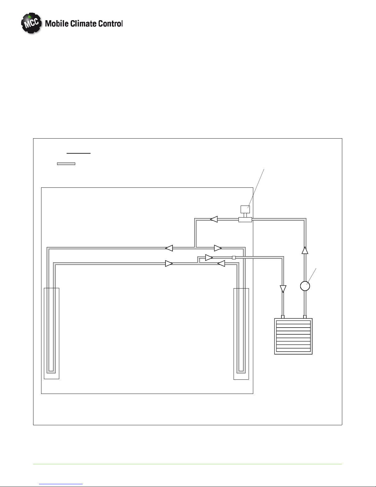
1.11 HEATING CYCLE
Heating circuit (See Figure 1-6) components
furnished by Mobile Climate Control include the
heater coils and a solenoid operated heat valve.
Components furnished by the bus manufacturer
include auxiliary heater and boost water pump. The
controller automatically controls the heat valve
during the heating and reheat mo des to maintain
required temperaturesinside the bus. Engine coolant
LEGEND
is circulated through the heating circuit by the engine
and an auxiliary boost water pump. When the heat
valve solenoid is energized, the valve will open to
allow engine coolant to flow through the heater coil.
The valve is normally closed so that if a failure occurs,
the system will be able to cool.
COOLANT
HEAT VALVE (Normally Closed)
INLET
OUTLET
BOOST
PUMP
EVAPORATOR
AC 353
© 2012 Mobile Climate Control T-348 Rev. 07/2012
MAIN ENGINE /
RADIATOR
Figure 1-7 Heat Flow Diagram
1--13
1.12 CONTROL PANEL WITH GR60 RELAY BOARD
1. Logic Board (See Figure 1-10)
2. RelayBoard-GR60(SeeFigure1-11)
3. Power Relay (ON)
Figure 1-8 Control Panel
2
15
4
3
4. Fresh Air
5. Terminal Block (TB)
© 2012 Mobile Climate Control T-348 Rev. 07/2012
1--14
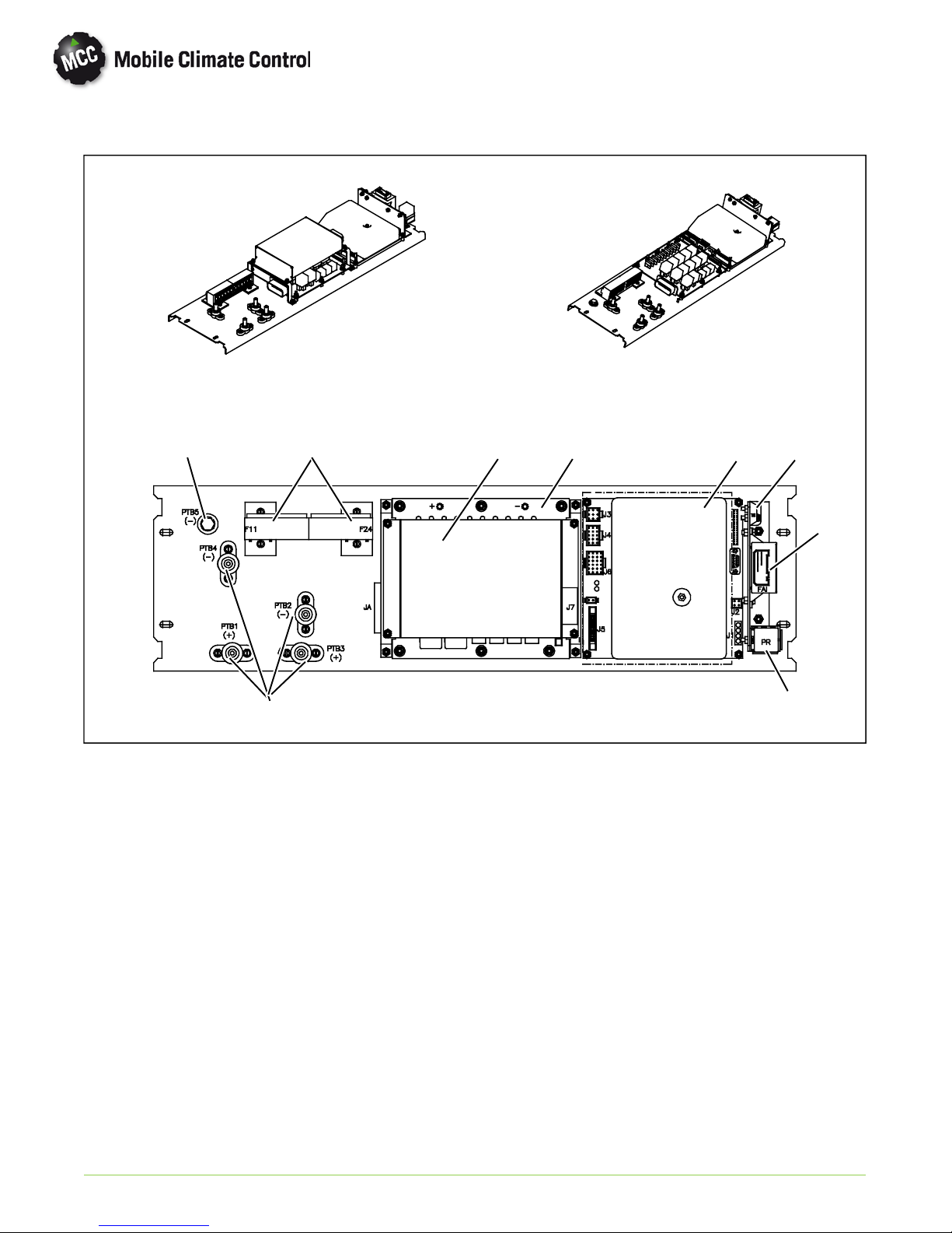
1.13 CONTROL PANEL
With CAN With/Out CAN
9
58
7
1. Logic Board (See Figure 1-10)
2. Relay Board (See Figure 1-12)
3. Logic Board, Data Communications
(See Figure 1-13
4. Power Relay (ON)
213
6
4
5. Fuses
6. Fresh Air
7. Power Terminal Block (PTB)
8. Terminal Block (TB)
9. Ground
Figure 1-9 Control Panel
© 2012 Mobile Climate Control T-348 Rev. 07/2012
1--15
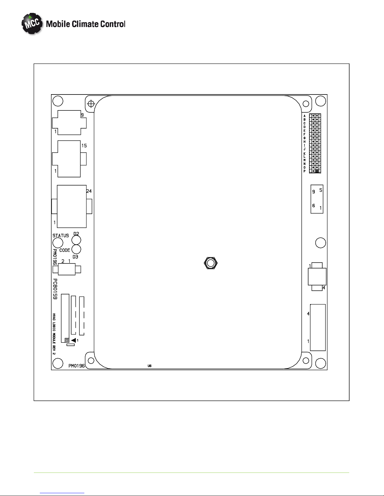
1.14 LOGIC BOARD
J3
J4
J
7
J6
J8
J
5
J7
J2
J1
J1 Logic board power in.
J2 Micromate Display interface.
J3 Manual control inputs.
J4 Interlock Inputs
(WTS, low side pressure switch etc.)
J5 Relay board interface.
J6 Sensor inputs (Thermistors, etc.).
© 2012 Mobile Climate Control T-348 Rev. 07/2012
J7 Diagnostics interface (RS232, DB9).
J8 Not used
D2 Blinks once per second in normal operation.
On steady to indicate alarms detected.
D3 Off In normal operation, blinks out alarm
codes (2 digits each) when alarms detected.
A-P Configuration Jumpers
Figure 1-10 Logic Board
1--16
 Loading...