

Page 1
Revision F
McAfee Network Security Platform
(XC-240 Quick Start Guide)
This quick start guide explains how to quickly set up and activate your McAfee® Network Security Platform XC-240
Load Balancer. The SFP+ (Small Form-factor Pluggable) Gigabit Ethernet ber ports are used.
The SFP+ modules are bundled along with your XC-240 device.
All product documentation referenced in this quick start guide is found on the McAfee Service Portal.
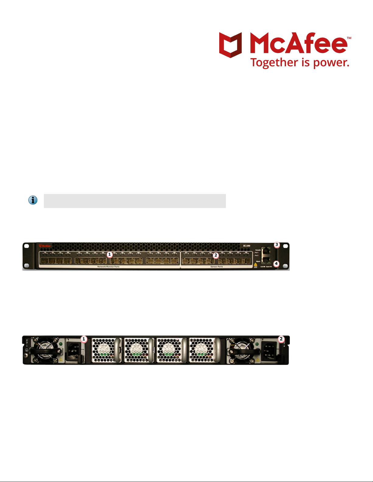
The XC-240 front panel
SFP+ 10 Gigabit Ethernet Monitoring ports (16)
1
SFP+ 10 Gigabit Sensor ports (8)
2
Console port (1)
3
10/100/1000 Management port (1)
4
The XC-240 rear panel
Power supply 1
1
Power supply 2
2
XC-240 Load Balancer setup overview
This section explains how to position and cable the various ports of your XC-240. This section also
how to install the Manager and then add the XC-240 to the Manager.
briey explains
1
Page 2
1 Position the XC-240
Install the XC-240 in a 19-inch rack using the rack mount ears.
a
Install SFP+ modules in the XC-240.
b
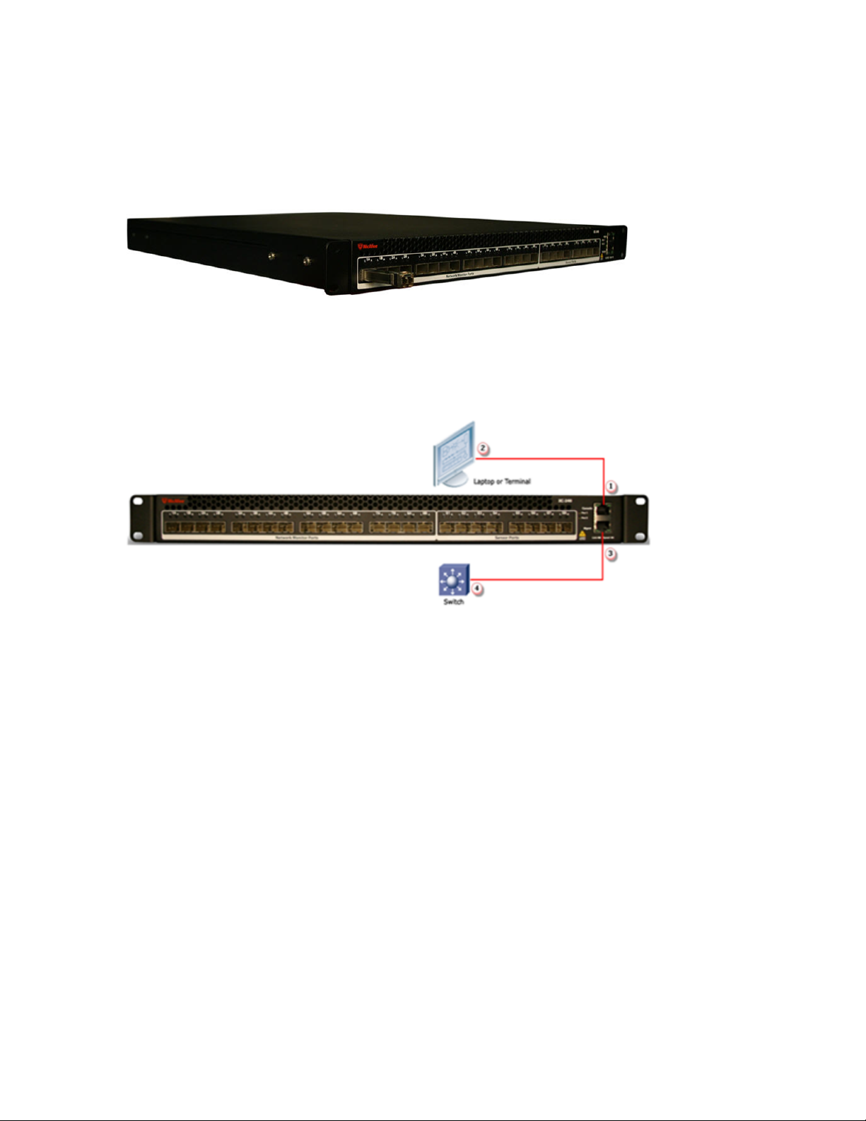
2 Cable the Management and Console ports
Plug a Category 5e Ethernet cable in the Mgmt (Management) port of XC-240.
a
Plug the other end of the cable into a network switch.
b
Plug the RS232 RJ45 cable supplied in the XC-240 box into the Console port.
c
Connect the other end of the Console port cable directly to a COM port of the computer or terminal
d
server you will be using to congure the XC-240 (for example, a computer running correctly congured
Windows Hyperterminal software). RJ45 to DB9 adapter has been provided. You must connect directly to
the console for initial conguration.
The required settings for Hyperterminal are:
• Baud rate: 115200 • Stop Bits: 1
• Number of Bits: 8 • Control Flow: None
• Parity: None
Plug the power cable into the power inlet and plug the other end into a power source. The XC-240 ships
e
with standard U.S. power and international cables.
2
Page 3
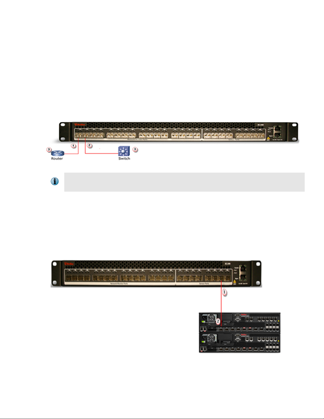
3 Cable the Monitoring ports
This procedure describes how to cable an XC-240 to run in In-line mode.
Plug the cable appropriate for use with the SFP+ module into one of the Monitoring ports labeled xA (for
a
example, 1A).
Plug another cable into the peer of the port used in 3a. This port will be labeled xB (for example, 1B).
b
Connect the other end of each cable to the network devices that you want to monitor. (For example, if
c
you plan to monitor trac between a switch and a router, connect the cable connected to 1A to the
router and the one connected to 1B to the switch.)
For instructions on how to cable the XC-240 to run in other operating modes, see the McAfee
Network Security Platform XC Cluster Administration Guide.
4 Cable the Sensor ports
This procedure describes how to connect the M-8000XC Sensor to the XC-240 Load Balancer.
Plug the ber cable appropriate for use with the SFP+ module into the Sensor port of the XC-240.
a
Connect the other end of the ber cable used in a into a 10G monitoring port, for example port 1A of the
b
M-8000XC Sensor.
3
Page 4

5 Conguring the XC-240
Congure the XC-240 following the steps given below:
Log on to the XC-240 using the terminal connected to the Console port.
a
At the prompt, log on using the default XC-240 username (admin) and password (admin123).
b
[Optional, but recommended]. Change the XC-240 password. At the prompt, type: user mod
c
name=admin pw=<new password> priv=2.
where <new password> is the new password.
Set the XC-240 IP address.
d
To congure an IPv4 address, type sysip set ipaddr=<IP address> mask=<netmask>
gw=<gateway>, where <ip address> is the IPv4 address for XC-240, <netmask> is the netmask, and
<gateway> is the IP address of the gateway. To congure an IPv6 address, type sysip inet6_set
ipaddr=<IP address> prefixlen=<prefix length>, where <ip address> is the IPv6 address for
XC-240.
Type sysip commit to activate the new IP address.
By default, the XC Cluster is
e
reserved for the peer XC-240 device. At the prompt, type: lbg show.
View the number of Sensor ports congured to load balance and the status of these ports, The ports are
down if they are displayed in braces, example, (s1),(s2),(s3)…(s6). The ports are up if they are not
displayed in braces, example, s1,s2,s3…s6.
congured with High Availability support in the 60G N+1 mode. Port S8 is
4
Page 5

Congure the mode of operation for the XC-240. At the prompt, type: lbg set ports.
f
Example for conguration in HA mode without Sensor redundancy (70G N):lbg set
ports=s1,s2,s3,s4,s5,s6,s7 group =1 OR lbg set ports=s1-s7 group=1.
Example for conguration in HA mode with Sensor redundancy (60G N+1):lbg set
ports=s1,s2,s3,s4,s5,s6 spares=s7 group =1 OR lbg set ports=s1-s6 spare=s7 group=1.
While using the lbg command, ensure that the Sensor ports being congured match with the
Sensors connected to the XC-240 in Step 4.
To change the mode of operation, see the McAfee Network Security Platform XC Cluster
Administration Guide.
Enable SNMP.
g
The SNMP agent is disabled by default. To enable and congure the SNMP agent:
a
At the prompt, type snmp set admin=<enable>.
To add the Manager IP to the XC-240, at the prompt type snmp trap_add name=<SNMP user
b
configured on the NSM while adding the XC-240> authProto=<authentication
protocol> authPass=<authentication password> privProto=<privacy protocol>
privPass=<privacy password> access=<rw> ip=<IP of the Manager> port=<4169>
admin=<enable>
Example: snmp trap_add name=nsmuser type=v3 ip=172.25.70.140 port=4169
authProto=SHA authPass=admin123 privProto=AES privPass=test123 admin=enable
access=rw.
To save and load the congurations, type snmp commit .
c
To view the SNMP user congurations, at the prompt type snmp user_show.
d
To exit the session, type exit.
h
6 Install the Manager software
For detailed instructions, refer to McAfee Network Security Platform Installation Guide.
You must have administrator privileges on the target Windows server to install the Manager
software.
MariaDB is included with the Manager and is installed (embedded) automatically on your target
Windows Server during this process.
The following steps briey explain the Manager installation:
Prepare the system according to the requirements outlined in McAfee Network Security Platform Installation
a
Guide and the McAfee Network Security Platform Release Notes.
Close all open applications.
b
Go to the McAfee Update Server and log on, using the grant number and password.
c
d Go to the Manager Software Updates folder and select the latest Manager software version available.
5
Page 6

Download the .zip le to the target Windows server and extract the setup le.
e
Double-click Manager_<version>_setup.exe and follow the on-screen prompts.
f
7 Start the Manager
Click Start | Programs | McAfee | Network Security Manager | Network Security Manager.
You do not require a license le for using Manager/Central Manager version 5.1.17.2 or above, and
6.0.7.x or above.
8 Add the XC-240 to the Manager
The Manager displays the Login page.
Log on to the Manager. The default Login ID is admin and the default Password is admin123.
a
b Click Configure.
c To add an XC-240 in the Manager, click Device List | Devices and then click New.
d Update information in the appropriate
elds and click Save.
6
Page 7

Repeat steps 8c-8d to add an M-8000XC Sensor. To add an M-8000XC Sensor, see the M-8000XC Sensor
Quick Start Guide.
Remember the values entered for the IP Address, SNMPv3 User, Authentication Password and Privacy
Password should match the ones
9 Add an XC Cluster
To add an XC Cluster:
To create an XC Cluster at least one M-8000XC Sensor and one XC-240 Load Balancer should have
been added.
a Click Device List | XC Clusters and then click New.
congured in Step 8d.
Move the added XC-240 Load Balancer and M-8000XC Sensor into the XC Cluster. Update information in
b
the appropriate elds and click Save.
For more information on adding the XC-240 Load Balancer, M-8000XC Sensors and XC Clusters,
see the McAfee Network Security Platform XC Cluster Administration Guide.
7
Page 8

10 Verify successful installation
After you have connected XC-240, verify that it is functioning correctly by checking the link LEDs for each of the
connected ports. The link LEDs should be illuminated to indicate that the links are up.
At the prompt, type: port show or lbg show, to verify all the ports are up and stats show to verify trac is
present.
11 You're up and running!
Your XC-240 Load Balancer is actively monitoring connected segments and load balancing the trac to the
congured Sensors.
Read the McAfee Network Security Platform XC Cluster Administration Guide for an overview of the Load
a
Balancing mechanism and detailed usage instructions. Click the Detailed Help buttons in the upper-right
corner of each window in the Manager.
Read the McAfee Network Security Platform M-8000XC Product Guide and McAfee Network Security Platform
b
M-8000XC Sensor Quick Start Guide for detailed usage instructions on the Sensor functions in an XC
Cluster.
Having problems? Check the McAfee Network Security Platform XC Cluster Administration Guide for
c
troubleshooting information.
Copyright © 2019 McAfee, LLC
McAfee and the McAfee logo are trademarks or registered trademarks of McAfee, LLC or its subsidiaries in the US and other countries. Other
marks and brands may be claimed as the property of others.
8 700-3503F00
 Loading...