

Page 1

McAfee® UTM Firewall
Administration Guide
version 4.0.4
Page 2

COPYRIGHT
Copyright © 2009 McAfee, Inc. All Rights Reserved.
No part of this publication may be reproduced, transmitted, transcribed, stored in a retrieval system, or translated into
any language in any form or by any means without the written permission of McAfee, Inc., or its suppliers or affiliate
companies.
TRADEMARK ATTRIBUTIONS
AVERT, EPO, EPOLICY ORCHESTRATOR, FLASHBOX, FOUNDSTONE, GROUPSHIELD, HERCULES, INTRUSHIELD ,
INTRUSION INTELLIGENCE, LINUXSHIELD, MANAGED MAIL PROTECTION, MAX (MCAFEE SECURITYALLIANCE
EXCHANGE), MCAFEE, MCAFEE.COM, NETSHIELD, PORTALSHIELD, PREVENTSYS, PROTECTION-IN-DEPTH STRATEGY,
PROTECTIONPILOT, SECURE MESSAGING SERVICE, SECURITYALLIANCE, SITEADVISOR, THREATSCAN, TOTAL
PROTECTION, VIREX, VIRUSSCAN, WEBSHIELD are registered trademarks or trademarks of McAfee, Inc. and/or its
affiliates in the US and/or other countries. McAfee Red in connection with security is distinctive of McAfee brand
products. All other registered and unregistered trademarks herein are the sole property of their respective owners.
LICENSE INFORMATION
License Agreement
NOTICE TO ALL USERS: CAREFULLY READ THE APPROPRIATE LEGAL AGREEMENT CORRESPONDING TO THE LICENSE
YOU PURCHASED, WHICH SETS FORTH THE GENERAL TERMS AND CONDITIONS FOR THE USE OF THE LICENSED
SOFTWARE. IF YOU DO NOT KNOW WHICH TYPE OF LICENSE YOU HAVE ACQUIRED, PLEASE CONSULT THE SALES AND
OTHER RELATED LICENSE GRANTOR PURCHASE ORDER DOCUMENTS THAT ACCOMPANIES YOUR SOFTWARE
PACKAGING OR THAT YOU HAVE RECEIVED SEPARATELY AS PART OF THE PURCHASE (AS A BOOKLET, A FILE ON THE
PRODUCT CD, OR A FILE AVAILABLE ON THE WEBSITE FROM WHICH YOU DOWNLOADED THE SOFTWARE PACKAGE).
IF YOU DO NOT AGREE TO ALL OF THE TERMS SET FORTH IN THE AGREEMENT, DO NOT INSTALL THE SOFTWARE. IF
APPLICABLE, YOU MAY RETURN THE PRODUCT TO MCAFEE OR THE PLACE OF PURCHASE FOR A FULL REFUND.
License Attributions
Refer to the product Release Notes.
Issued August 2009 / McAfee UTM Firewall version 4.0.4
Page 3

Contents
About this Document 9
1 Introduction 11
UTM Firewall desktop appliances . . . . . . . . . . . . . . . . . . . . . . . . . . . . . . . . . . . . . . . . . . . . . . . . . . . .11
UTM Firewall rack mount appliance . . . . . . . . . . . . . . . . . . . . . . . . . . . . . . . . . . . . . . . . . . . . . . . . . .14
UTM Firewall PCI appliance . . . . . . . . . . . . . . . . . . . . . . . . . . . . . . . . . . . . . . . . . . . . . . . . . . . . . . . .15
UTM Firewall Management Console . . . . . . . . . . . . . . . . . . . . . . . . . . . . . . . . . . . . . . . . . . . . . . . . . .16
UTM Firewall menus . . . . . . . . . . . . . . . . . . . . . . . . . . . . . . . . . . . . . . . . . . . . . . . . . . . . . . . . . . . . .17
Interface icons . . . . . . . . . . . . . . . . . . . . . . . . . . . . . . . . . . . . . . . . . . . . . . . . . . . . . . . . . . . . . . . .19
Help and Support menu option . . . . . . . . . . . . . . . . . . . . . . . . . . . . . . . . . . . . . . . . . . . . . . . . . . . . .21
Front panel LEDs . . . . . . . . . . . . . . . . . . . . . . . . . . . . . . . . . . . . . . . . . . . . . . . . . . . . . . . . . . . .12
Rear panel . . . . . . . . . . . . . . . . . . . . . . . . . . . . . . . . . . . . . . . . . . . . . . . . . . . . . . . . . . . . . . . . .13
Physical specifications . . . . . . . . . . . . . . . . . . . . . . . . . . . . . . . . . . . . . . . . . . . . . . . . . . . . . . . . .13
Front panel LEDs . . . . . . . . . . . . . . . . . . . . . . . . . . . . . . . . . . . . . . . . . . . . . . . . . . . . . . . . . . . .14
Front panel . . . . . . . . . . . . . . . . . . . . . . . . . . . . . . . . . . . . . . . . . . . . . . . . . . . . . . . . . . . . . . . .14
Rear panel . . . . . . . . . . . . . . . . . . . . . . . . . . . . . . . . . . . . . . . . . . . . . . . . . . . . . . . . . . . . . . . . .14
Physical specifications . . . . . . . . . . . . . . . . . . . . . . . . . . . . . . . . . . . . . . . . . . . . . . . . . . . . . . . . .14
Bridged mode . . . . . . . . . . . . . . . . . . . . . . . . . . . . . . . . . . . . . . . . . . . . . . . . . . . . . . . . . . . . . . .15
LEDs . . . . . . . . . . . . . . . . . . . . . . . . . . . . . . . . . . . . . . . . . . . . . . . . . . . . . . . . . . . . . . . . . . . . .16
Physical specifications . . . . . . . . . . . . . . . . . . . . . . . . . . . . . . . . . . . . . . . . . . . . . . . . . . . . . . . . .16
Home icon . . . . . . . . . . . . . . . . . . . . . . . . . . . . . . . . . . . . . . . . . . . . . . . . . . . . . . . . . . . . . . . . .19
Logout icon . . . . . . . . . . . . . . . . . . . . . . . . . . . . . . . . . . . . . . . . . . . . . . . . . . . . . . . . . . . . . . . .19
Backup and restore icon . . . . . . . . . . . . . . . . . . . . . . . . . . . . . . . . . . . . . . . . . . . . . . . . . . . . . . .20
Online help icon . . . . . . . . . . . . . . . . . . . . . . . . . . . . . . . . . . . . . . . . . . . . . . . . . . . . . . . . . . . . .20
Edit and delete icons . . . . . . . . . . . . . . . . . . . . . . . . . . . . . . . . . . . . . . . . . . . . . . . . . . . . . . . . . .20
Add above and below icons . . . . . . . . . . . . . . . . . . . . . . . . . . . . . . . . . . . . . . . . . . . . . . . . . . . . .20
Tooltips . . . . . . . . . . . . . . . . . . . . . . . . . . . . . . . . . . . . . . . . . . . . . . . . . . . . . . . . . . . . . . . . . . .20
Online Help page . . . . . . . . . . . . . . . . . . . . . . . . . . . . . . . . . . . . . . . . . . . . . . . . . . . . . . . . . . . .21
Technical Support page . . . . . . . . . . . . . . . . . . . . . . . . . . . . . . . . . . . . . . . . . . . . . . . . . . . . . . . .21
Technical Support Report page . . . . . . . . . . . . . . . . . . . . . . . . . . . . . . . . . . . . . . . . . . . . . . . . . . .22
2 Getting Started 23
Overview . . . . . . . . . . . . . . . . . . . . . . . . . . . . . . . . . . . . . . . . . . . . . . . . . . . . . . . . . . . . . . . . . . . . 23
Powering on the device . . . . . . . . . . . . . . . . . . . . . . . . . . . . . . . . . . . . . . . . . . . . . . . . . . . . . . . . . . .23
Connecting an administrative PC to the device . . . . . . . . . . . . . . . . . . . . . . . . . . . . . . . . . . . . . . . . . .24
Setting password and LAN connection settings . . . . . . . . . . . . . . . . . . . . . . . . . . . . . . . . . . . . . . . . . .24
Configuring the UTM Firewall switch . . . . . . . . . . . . . . . . . . . . . . . . . . . . . . . . . . . . . . . . . . . . . . . . . .29
Selecting an initial firewall level . . . . . . . . . . . . . . . . . . . . . . . . . . . . . . . . . . . . . . . . . . . . . . . . . . . . .30
Confirming settings . . . . . . . . . . . . . . . . . . . . . . . . . . . . . . . . . . . . . . . . . . . . . . . . . . . . . . . . . . . . .31
Setting up the PCs on your LAN . . . . . . . . . . . . . . . . . . . . . . . . . . . . . . . . . . . . . . . . . . . . . . . . . . . . .31
Automatic LAN configuration using the UTM Firewall DHCP server . . . . . . . . . . . . . . . . . . . . . . . . . . .32
Automatic LAN configuration using an existing DHCP server . . . . . . . . . . . . . . . . . . . . . . . . . . . . . . .32
Manual LAN configuration . . . . . . . . . . . . . . . . . . . . . . . . . . . . . . . . . . . . . . . . . . . . . . . . . . . . . .33
Registering your UTM Firewall . . . . . . . . . . . . . . . . . . . . . . . . . . . . . . . . . . . . . . . . . . . . . . . . . . . . . .33
Using the My Secure Computing website . . . . . . . . . . . . . . . . . . . . . . . . . . . . . . . . . . . . . . . . . . . .34
Creating an account . . . . . . . . . . . . . . . . . . . . . . . . . . . . . . . . . . . . . . . . . . . . . . . . . . . . . . . . . .34
Adding your UTM Firewall appliance . . . . . . . . . . . . . . . . . . . . . . . . . . . . . . . . . . . . . . . . . . . . . . .35
Activating a feature . . . . . . . . . . . . . . . . . . . . . . . . . . . . . . . . . . . . . . . . . . . . . . . . . . . . . . . . . . .37
Retrieving license information for add-on products . . . . . . . . . . . . . . . . . . . . . . . . . . . . . . . . . . . . .38
3 Network Setup menu options 41
Network overview . . . . . . . . . . . . . . . . . . . . . . . . . . . . . . . . . . . . . . . . . . . . . . . . . . . . . . . . . . . . . .41
Quick Setup wizard . . . . . . . . . . . . . . . . . . . . . . . . . . . . . . . . . . . . . . . . . . . . . . . . . . . . . . . . . . . . .42
Network setup . . . . . . . . . . . . . . . . . . . . . . . . . . . . . . . . . . . . . . . . . . . . . . . . . . . . . . . . . . . . . . . . .42
Multifunction vs. fixed-function ports . . . . . . . . . . . . . . . . . . . . . . . . . . . . . . . . . . . . . . . . . . . . . . .42
McAfee UTM Firewall 4.0.4 Administration Guide 3
Page 4

Contents
Connections . . . . . . . . . . . . . . . . . . . . . . . . . . . . . . . . . . . . . . . . . . . . . . . . . . . . . . . . . . . . . . . .42
Direct connection overview . . . . . . . . . . . . . . . . . . . . . . . . . . . . . . . . . . . . . . . . . . . . . . . . . . . . .44
Direct Connection Settings page . . . . . . . . . . . . . . . . . . . . . . . . . . . . . . . . . . . . . . . . . . . . . . . . . .44
Ethernet Configuration tab . . . . . . . . . . . . . . . . . . . . . . . . . . . . . . . . . . . . . . . . . . . . . . . . . . . . . .45
Aliases tab . . . . . . . . . . . . . . . . . . . . . . . . . . . . . . . . . . . . . . . . . . . . . . . . . . . . . . . . . . . . . . . . .47
Enabling IPv6 for a connection . . . . . . . . . . . . . . . . . . . . . . . . . . . . . . . . . . . . . . . . . . . . . . . . . . .48
ADSL . . . . . . . . . . . . . . . . . . . . . . . . . . . . . . . . . . . . . . . . . . . . . . . . . . . . . . . . . . . . . . . . . . . . . . .48
Routed versus bridged DSL modems . . . . . . . . . . . . . . . . . . . . . . . . . . . . . . . . . . . . . . . . . . . . . . .49
Accessing the ADSL connection methods page . . . . . . . . . . . . . . . . . . . . . . . . . . . . . . . . . . . . . . . .50
Connecting with a cable modem . . . . . . . . . . . . . . . . . . . . . . . . . . . . . . . . . . . . . . . . . . . . . . . . . . . .54
Configuring a dialout connection on the COM port . . . . . . . . . . . . . . . . . . . . . . . . . . . . . . . . . . . . . . . .56
Configuring dialout port settings . . . . . . . . . . . . . . . . . . . . . . . . . . . . . . . . . . . . . . . . . . . . . . . . . .58
Enabling dial on demand for a connection . . . . . . . . . . . . . . . . . . . . . . . . . . . . . . . . . . . . . . . . . . .59
Configuring static IP addresses for a connection . . . . . . . . . . . . . . . . . . . . . . . . . . . . . . . . . . . . . . .60
Configuring interface aliases for a connection . . . . . . . . . . . . . . . . . . . . . . . . . . . . . . . . . . . . . . . . .60
Setting up dial-in access . . . . . . . . . . . . . . . . . . . . . . . . . . . . . . . . . . . . . . . . . . . . . . . . . . . . . . . . . .61
Dial-in setup . . . . . . . . . . . . . . . . . . . . . . . . . . . . . . . . . . . . . . . . . . . . . . . . . . . . . . . . . . . . . . .61
Connecting a dial-in client . . . . . . . . . . . . . . . . . . . . . . . . . . . . . . . . . . . . . . . . . . . . . . . . . . . . . .63
Failover, load balancing, and high availability . . . . . . . . . . . . . . . . . . . . . . . . . . . . . . . . . . . . . . . . . . .67
Internet connection failover . . . . . . . . . . . . . . . . . . . . . . . . . . . . . . . . . . . . . . . . . . . . . . . . . . . . . . .69
Editing failover connection parameters . . . . . . . . . . . . . . . . . . . . . . . . . . . . . . . . . . . . . . . . . . . . .69
Load balancing . . . . . . . . . . . . . . . . . . . . . . . . . . . . . . . . . . . . . . . . . . . . . . . . . . . . . . . . . . . . . .73
Enabling load balancing . . . . . . . . . . . . . . . . . . . . . . . . . . . . . . . . . . . . . . . . . . . . . . . . . . . . . . . .73
High Availability . . . . . . . . . . . . . . . . . . . . . . . . . . . . . . . . . . . . . . . . . . . . . . . . . . . . . . . . . . . . . . . .74
Default high availability script . . . . . . . . . . . . . . . . . . . . . . . . . . . . . . . . . . . . . . . . . . . . . . . . . . .77
Enabling high availability . . . . . . . . . . . . . . . . . . . . . . . . . . . . . . . . . . . . . . . . . . . . . . . . . . . . . . .78
Configuring high availability . . . . . . . . . . . . . . . . . . . . . . . . . . . . . . . . . . . . . . . . . . . . . . . . . . . . .78
DMZ network . . . . . . . . . . . . . . . . . . . . . . . . . . . . . . . . . . . . . . . . . . . . . . . . . . . . . . . . . . . . . . . . . .80
Configuring a DMZ connection . . . . . . . . . . . . . . . . . . . . . . . . . . . . . . . . . . . . . . . . . . . . . . . . . . .80
Services on the DMZ network . . . . . . . . . . . . . . . . . . . . . . . . . . . . . . . . . . . . . . . . . . . . . . . . . . . .81
Guest network . . . . . . . . . . . . . . . . . . . . . . . . . . . . . . . . . . . . . . . . . . . . . . . . . . . . . . . . . . . . . . . . .82
Configuring a guest connection . . . . . . . . . . . . . . . . . . . . . . . . . . . . . . . . . . . . . . . . . . . . . . . . . . .82
Wireless . . . . . . . . . . . . . . . . . . . . . . . . . . . . . . . . . . . . . . . . . . . . . . . . . . . . . . . . . . . . . . . . . . . . .82
Wireless security methods . . . . . . . . . . . . . . . . . . . . . . . . . . . . . . . . . . . . . . . . . . . . . . . . . . . . . .83
Configuring a wireless connection . . . . . . . . . . . . . . . . . . . . . . . . . . . . . . . . . . . . . . . . . . . . . . . . .83
Bridging wireless and LAN connections . . . . . . . . . . . . . . . . . . . . . . . . . . . . . . . . . . . . . . . . . . . . .88
Configuring Wireless MAC-based ACL . . . . . . . . . . . . . . . . . . . . . . . . . . . . . . . . . . . . . . . . . . . . . .89
Configuring WDS . . . . . . . . . . . . . . . . . . . . . . . . . . . . . . . . . . . . . . . . . . . . . . . . . . . . . . . . . . . .90
Configuring advanced wireless features . . . . . . . . . . . . . . . . . . . . . . . . . . . . . . . . . . . . . . . . . . . . .92
Bridging . . . . . . . . . . . . . . . . . . . . . . . . . . . . . . . . . . . . . . . . . . . . . . . . . . . . . . . . . . . . . . . . . . . . .9 4
Adding a bridged interface . . . . . . . . . . . . . . . . . . . . . . . . . . . . . . . . . . . . . . . . . . . . . . . . . . . . . .94
Deleting a bridge . . . . . . . . . . . . . . . . . . . . . . . . . . . . . . . . . . . . . . . . . . . . . . . . . . . . . . . . . . . .98
Bridging across a VPN connection . . . . . . . . . . . . . . . . . . . . . . . . . . . . . . . . . . . . . . . . . . . . . . . . .98
VLAN . . . . . . . . . . . . . . . . . . . . . . . . . . . . . . . . . . . . . . . . . . . . . . . . . . . . . . . . . . . . . . . . . . . . . . .99
Adding a VLAN . . . . . . . . . . . . . . . . . . . . . . . . . . . . . . . . . . . . . . . . . . . . . . . . . . . . . . . . . . . . . .99
Port-Based VLANs . . . . . . . . . . . . . . . . . . . . . . . . . . . . . . . . . . . . . . . . . . . . . . . . . . . . . . . . . . .100
Enabling port-based VLANs . . . . . . . . . . . . . . . . . . . . . . . . . . . . . . . . . . . . . . . . . . . . . . . . . . . . 101
Adding a port-based VLAN . . . . . . . . . . . . . . . . . . . . . . . . . . . . . . . . . . . . . . . . . . . . . . . . . . . . . 102
GRE tunnels . . . . . . . . . . . . . . . . . . . . . . . . . . . . . . . . . . . . . . . . . . . . . . . . . . . . . . . . . . . . . . .104
Troubleshooting GRE tunnels . . . . . . . . . . . . . . . . . . . . . . . . . . . . . . . . . . . . . . . . . . . . . . . . . . . 105
3G USB Modems . . . . . . . . . . . . . . . . . . . . . . . . . . . . . . . . . . . . . . . . . . . . . . . . . . . . . . . .
figuring 3G USB modem connections . . . . . . . . . . . . . . . . . . . . . . . . . . . . . . . . . . . . . . . . . . . 106
Con
Configuring USB port settings . . . . . . . . . . . . . . . . . . . . . . . . . . . . . . . . . . . . . . . . . . . . . . . . . . . 107
Adding new 3G USB modem profiles . . . . . . . . . . . . . . . . . . . . . . . . . . . . . . . . . . . . . . . . . . . . . .108
Routes . . . . . . . . . . . . . . . . . . . . . . . . . . . . . . . . . . . . . . . . . . . . . . . . . . . . . . . . . . . . . . . . . . . . . 109
Creating a static route . . . . . . . . . . . . . . . . . . . . . . . . . . . . . . . . . . . . . . . . . . . . . . . . . . . . . . . . 109
Policy Routes page . . . . . . . . . . . . . . . . . . . . . . . . . . . . . . . . . . . . . . . . . . . . . . . . . . . . . . . . . . 111
Enabling route management . . . . . . . . . . . . . . . . . . . . . . . . . . . . . . . . . . . . . . . . . . . . . . . . . . .112
Manually configuring route management . . . . . . . . . . . . . . . . . . . . . . . . . . . . . . . . . . . . . . . . . . . 113
Example: Configuring RIP Route Management . . . . . . . . . . . . . . . . . . . . . . . . . . . . . . . . . . . . . . . 113
Example: OSPF . . . . . . . . . . . . . . . . . . . . . . . . . . . . . . . . . . . . . . . . . . . . . . . . . . . . . . . . . . . . . 115
Example: BGP . . . . . . . . . . . . . . . . . . . . . . . . . . . . . . . . . . . . . . . . . . . . . . . . . . . . . . . . . . . . .116
DNS . . . . . . . . . . . . . . . . . . . . . . . . . . . . . . . . . . . . . . . . . . . . . . . . . . . . . . . . . . . . . . . . . . . . . . . 117
. . . . . . 106
4 McAfee UTM Firewall 4.0.4 Administration Guide
Page 5

Contents
DNS Proxy tab . . . . . . . . . . . . . . . . . . . . . . . . . . . . . . . . . . . . . . . . . . . . . . . . . . . . . . . . . . . . . 118
Dynamic DNS tab . . . . . . . . . . . . . . . . . . . . . . . . . . . . . . . . . . . . . . . . . . . . . . . . . . . . . . . . . . .119
Static Hosts tab . . . . . . . . . . . . . . . . . . . . . . . . . . . . . . . . . . . . . . . . . . . . . . . . . . . . . . . . . . . .121
IPv6 . . . . . . . . . . . . . . . . . . . . . . . . . . . . . . . . . . . . . . . . . . . . . . . . . . . . . . . . . . . . . . . . . . . . . . .122
Enabling IPv6 at the appliance level . . . . . . . . . . . . . . . . . . . . . . . . . . . . . . . . . . . . . . . . . . . . . .123
DHCP Server . . . . . . . . . . . . . . . . . . . . . . . . . . . . . . . . . . . . . . . . . . . . . . . . . . . . . . . . . . . . . . . . . 123
DHCP Status page . . . . . . . . . . . . . . . . . . . . . . . . . . . . . . . . . . . . . . . . . . . . . . . . . . . . . . . . . . . 124
DHCP Addresses page . . . . . . . . . . . . . . . . . . . . . . . . . . . . . . . . . . . . . . . . . . . . . . . . . . . . . . . . 126
DHCP Relay page . . . . . . . . . . . . . . . . . . . . . . . . . . . . . . . . . . . . . . . . . . . . . . . . . . . . . . . . . . .130
Configuring the Windows client for DHCP . . . . . . . . . . . . . . . . . . . . . . . . . . . . . . . . . . . . . . . . . . . 131
Verifying and troubleshooting DHCP . . . . . . . . . . . . . . . . . . . . . . . . . . . . . . . . . . . . . . . . . . . . . .132
Web cache . . . . . . . . . . . . . . . . . . . . . . . . . . . . . . . . . . . . . . . . . . . . . . . . . . . . . . . . . . . . . . . . . . 132
Enabling the Web cache . . . . . . . . . . . . . . . . . . . . . . . . . . . . . . . . . . . . . . . . . . . . . . . . . . . . . . . 133
Creating a user account and network share in Windows XP . . . . . . . . . . . . . . . . . . . . . . . . . . . . . . 134
Allocating network storage for Web cache . . . . . . . . . . . . . . . . . . . . . . . . . . . . . . . . . . . . . . . . . . 135
Configuring browsers to use the Web cache . . . . . . . . . . . . . . . . . . . . . . . . . . . . . . . . . . . . . . . . . 136
Allocating local USB storage for Web caching . . . . . . . . . . . . . . . . . . . . . . . . . . . . . . . . . . . . . . . . 138
Configuring Web Cache Peers . . . . . . . . . . . . . . . . . . . . . . . . . . . . . . . . . . . . . . . . . . . . . . . . . . .138
Configuring ICAP client for Web Cache . . . . . . . . . . . . . . . . . . . . . . . . . . . . . . . . . . . . . . . . . . . .139
Configuring advanced settings for the Web cache . . . . . . . . . . . . . . . . . . . . . . . . . . . . . . . . . . . . . 140
Traffic Shaping . . . . . . . . . . . . . . . . . . . . . . . . . . . . . . . . . . . . . . . . . . . . . . . . . . . . . . . . . . . . . . .141
Enabling QoS Autoshaper . . . . . . . . . . . . . . . . . . . . . . . . . . . . . . . . . . . . . . . . . . . . . . . . . . . . . . 142
About ToS packet priority . . . . . . . . . . . . . . . . . . . . . . . . . . . . . . . . . . . . . . . . . . . . . . . . . . . . .143
SIP . . . . . . . . . . . . . . . . . . . . . . . . . . . . . . . . . . . . . . . . . . . . . . . . . . . . . . . . . . . . . . . . . . . . . . . .1 46
Enabling the SIP proxy . . . . . . . . . . . . . . . . . . . . . . . . . . . . . . . . . . . . . . . . . . . . . . . . . . . . . . . 147
4 Firewall menu options 149
Controlling packet traffic . . . . . . . . . . . . . . . . . . . . . . . . . . . . . . . . . . . . . . . . . . . . . . . . . . . . . . . . .149
Firewall overview . . . . . . . . . . . . . . . . . . . . . . . . . . . . . . . . . . . . . . . . . . . . . . . . . . . . . . . . . . . . . .151
Definitions . . . . . . . . . . . . . . . . . . . . . . . . . . . . . . . . . . . . . . . . . . . . . . . . . . . . . . . . . . . . . . . . . . 1 52
Service Groups page . . . . . . . . . . . . . . . . . . . . . . . . . . . . . . . . . . . . . . . . . . . . . . . . . . . . . . . . .152
Addresses page . . . . . . . . . . . . . . . . . . . . . . . . . . . . . . . . . . . . . . . . . . . . . . . . . . . . . . . . . . . .155
Interfaces page . . . . . . . . . . . . . . . . . . . . . . . . . . . . . . . . . . . . . . . . . . . . . . . . . . . . . . . . . . . . 157
Packet filtering . . . . . . . . . . . . . . . . . . . . . . . . . . . . . . . . . . . . . . . . . . . . . . . . . . . . . . . . . . . . . . . 159
Packet filtering actions . . . . . . . . . . . . . . . . . . . . . . . . . . . . . . . . . . . . . . . . . . . . . . . . . . . . . . . 160
Packet Filtering page . . . . . . . . . . . . . . . . . . . . . . . . . . . . . . . . . . . . . . . . . . . . . . . . . . . . . . . . . 161
Incoming access . . . . . . . . . . . . . . . . . . . . . . . . . . . . . . . . . . . . . . . . . . . . . . . . . . . . . . . . . . . .167
About custom firewall rules . . . . . . . . . . . . . . . . . . . . . . . . . . . . . . . . . . . . . . . . . . . . . . . . . . . . 168
NAT . . . . . . . . . . . . . . . . . . . . . . . . . . . . . . . . . . . . . . . . . . . . . . . . . . . . . . . . . . . . . . . . . . . . . . . 171
About port forwarding . . . . . . . . . . . . . . . . . . . . . . . . . . . . . . . . . . . . . . . . . . . . . . . . . . . . . . . .172
About masquerading and source NAT . . . . . . . . . . . . . . . . . . . . . . . . . . . . . . . . . . . . . . . . . . . . . 172
About one-to-one NAT . . . . . . . . . . . . . . . . . . . . . . . . . . . . . . . . . . . . . . . . . . . . . . . . . . . . . . . . 173
Port forwarding page . . . . . . . . . . . . . . . . . . . . . . . . . . . . . . . . . . . . . . . . . . . . . . . . . . . . . . . . . 173
Source NAT page . . . . . . . . . . . . . . . . . . . . . . . . . . . . . . . . . . . . . . . . . . . . . . . . . . . . . . . . . . . 180
One-to-one NAT . . . . . . . . . . . . . . . . . . . . . . . . . . . . . . . . . . . . . . . . . . . . . . . . . . . . . . . . . . . .184
Masquerading page . . . . . . . . . . . . . . . . . . . . . . . . . . . . . . . . . . . . . . . . . . . . . . . . . . . . . . . . . .186
Universal Plug and Play Gateway . . . . . . . . . . . . . . . . . . . . . . . . . . . . . . . . . . . . . . . . . . . . . . . .187
Configuring UPnP rules from Windows XP . . . . . . . . . . . . . . . . . . . . . . . . . . . . . . . . . . . . . . . . . . . 188
Connection tracking . . . . . . . . . . . . . . . . . . . . . . . . . . . . . . . . . . . . . . . . . . . . . . . . . . . . . . . . . . . . 190
Supported Protocols . . . . . . . . . . . . . . . . . . . . . . . . . . . . . . . . . . . . . . . . . . . . . . . . . . . . . . . . .191
Connection logging . . . . . . . . . . . . . . . . . . . . . . . . . . . . . . . . . . . . . . . . . . . . . . . . . . . . . . . . . . 191
Preventing connection flooding . . . . . . . . . . . . . . . . . . . . . . . . . . . . . . . . . . . . . . . . . . . . . . . . . .191
Configuring connection tracking . . . . . . . . . . . . . . . . . . . . . . . . . . . . . . . . . . . . . . . . . . . . . . . . . 191
Disabling connection tracking . . . . . . . . . . . . . . . . . . . . . . . . . . . . . . . . . . . . . . . . . . . . . . . . . . .193
About the Connection Tracking Report . . . . . . . . . . . . . . . . . . . . . . . . . . . . . . . . . . . . . . . . . . . . . 193
Viewing the connection tracking report in the console . . . . . . . . . . . . . . . . . . . . . . . . . . . . . . . . . . 194
Downloading the connection tracking report . . . . . . . . . . . . . . . . . . . . . . . . . . . . . . . . . . . . . . . . . 195
Example: Creating a connection tracking re port . . . . . . . . . . . . . . . . . . . . . . . . . . . . . . . . . . . . . . 195
Intrusion Detection Systems . . . . . . . . . . . . . . . . . . . . . . . . . . . . . . . . . . . . . . . . . . . . . . . . . . . . . . 195
Benefits of using an IDS . . . . . . . . . . . . . . . . . . . . . . . . . . . . . . . . . . . . . . . . . . . . . . . . . . . . . .196
Basic IDB . . . . . . . . . . . . . . . . . . . . . . . . . . . . . . . . . . . . . . . . . . . . . . . . . . . . . . . . . . . . . . . . .196
Configuring basic IDB . . . . . . . . . . . . . . . . . . . . . . . . . . . . . . . . . . . . . . . . . . . . . . . . . . . . . . . . 197
Selecting TCP dummy services . . . . . . . . . . . . . . . . . . . . . . . . . . . . . . . . . . . . . . . . . . . . . . . . . .197
McAfee UTM Firewall 4.0.4 Administration Guide 5
Page 6

Contents
Selecting UDP dummy services . . . . . . . . . . . . . . . . . . . . . . . . . . . . . . . . . . . . . . . . . . . . . . . . . .199
Advanced Intrusion Detection and Prevention . . . . . . . . . . . . . . . . . . . . . . . . . . . . . . . . . . . . . . . . . .201
About rule sets . . . . . . . . . . . . . . . . . . . . . . . . . . . . . . . . . . . . . . . . . . . . . . . . . . . . . . . . . . . . .201
Configuring Snort in IPS mode . . . . . . . . . . . . . . . . . . . . . . . . . . . . . . . . . . . . . . . . . . . . . . . . . .202
Configuring Snort in IDS mode . . . . . . . . . . . . . . . . . . . . . . . . . . . . . . . . . . . . . . . . . . . . . . . . . .202
Logging to an analysis server (Snort ID S only) . . . . . . . . . . . . . . . . . . . . . . . . . . . . . . . . . . . . . . . 204
Setting up the analysis server for Snort IDS . . . . . . . . . . . . . . . . . . . . . . . . . . . . . . . . . . . . . . . . 204
Access control . . . . . . . . . . . . . . . . . . . . . . . . . . . . . . . . . . . . . . . . . . . . . . . . . . . . . . . . . . . . . . . . 205
Authorizations page . . . . . . . . . . . . . . . . . . . . . . . . . . . . . . . . . . . . . . . . . . . . . . . . . . . . . . . . . 206
User authentication for Internet access . . . . . . . . . . . . . . . . . . . . . . . . . . . . . . . . . . . . . . . . . . . .207
Configuring browsers to use the appliance Web proxy . . . . . . . . . . . . . . . . . . . . . . . . . . . . . . . . . . 208
ACL tab . . . . . . . . . . . . . . . . . . . . . . . . . . . . . . . . . . . . . . . . . . . . . . . . . . . . . . . . . . . . . . . . . . 210
Web Lists tab . . . . . . . . . . . . . . . . . . . . . . . . . . . . . . . . . . . . . . . . . . . . . . . . . . . . . . . . . . . . . . 211
Policy enforcement . . . . . . . . . . . . . . . . . . . . . . . . . . . . . . . . . . . . . . . . . . . . . . . . . . . . . . . . . . 212
Managing policy enforcement scripts . . . . . . . . . . . . . . . . . . . . . . . . . . . . . . . . . . . . . . . . . . . . . .215
McAfee Web Protection Service . . . . . . . . . . . . . . . . . . . . . . . . . . . . . . . . . . . . . . . . . . . . . . . . . .216
McAfee Web Gateway web filtering service . . . . . . . . . . . . . . . . . . . . . . . . . . . . . . . . . . . . . . . . . . 217
Uploading a McAfee Web Gateway certificate an d key . . . . . . . . . . . . . . . . . . . . . . . . . . . . . . . . . . 219
Copying and pasting a McAfee Web Gateway certifi cate and key . . . . . . . . . . . . . . . . . . . . . . . . . . . 219
Blocking categories for McAfee Web Gateway filtering . . . . . . . . . . . . . . . . . . . . . . . . . . . . . . . . . . 220
Antivirus . . . . . . . . . . . . . . . . . . . . . . . . . . . . . . . . . . . . . . . . . . . . . . . . . . . . . . . . . . . . . . . . . . . .222
Enabling antivirus . . . . . . . . . . . . . . . . . . . . . . . . . . . . . . . . . . . . . . . . . . . . . . . . . . . . . . . . . . . 223
Manually downloading antivirus database files . . . . . . . . . . . . . . . . . . . . . . . . . . . . . . . . . . . . . . . 225
Auxiliary storage for virus scanning . . . . . . . . . . . . . . . . . . . . . . . . . . . . . . . . . . . . . . . . . . . . . . . 226
Virus scanning POP email . . . . . . . . . . . . . . . . . . . . . . . . . . . . . . . . . . . . . . . . . . . . . . . . . . . . . . 228
Virus scanning SMTP email . . . . . . . . . . . . . . . . . . . . . . . . . . . . . . . . . . . . . . . . . . . . . . . . . . . . . 229
Virus scanning Web traffic . . . . . . . . . . . . . . . . . . . . . . . . . . . . . . . . . . . . . . . . . . . . . . . . . . . . . 231
Enabling FTP virus scanning . . . . . . . . . . . . . . . . . . . . . . . . . . . . . . . . . . . . . . . . . . . . . . . . . . . . 231
Antispam (TrustedSource) . . . . . . . . . . . . . . . . . . . . . . . . . . . . . . . . . . . . . . . . . . . . . . . . . . . . . . . 233
About TrustedSource . . . . . . . . . . . . . . . . . . . . . . . . . . . . . . . . . . . . . . . . . . . . . . . . . . . . . . . . .233
Enabling TrustedSource . . . . . . . . . . . . . . . . . . . . . . . . . . . . . . . . . . . . . . . . . . . . . . . . . . . . . . . 234
5 VPN menu features 239
VPN overview . . . . . . . . . . . . . . . . . . . . . . . . . . . . . . . . . . . . . . . . . . . . . . . . . . . . . . . . . . . . . . . . 239
About PPTP . . . . . . . . . . . . . . . . . . . . . . . . . . . . . . . . . . . . . . . . . . . . . . . . . . . . . . . . . . . . . . . . . . 240
PPTP VPN Client . . . . . . . . . . . . . . . . . . . . . . . . . . . . . . . . . . . . . . . . . . . . . . . . . . . . . . . . . . . . . . . 240
PPTP VPN Server . . . . . . . . . . . . . . . . . . . . . . . . . . . . . . . . . . . . . . . . . . . . . . . . . . . . . . . . . . . . . . 242
Enabling and configuring the PPTP VPN Server . . . . . . . . . . . . . . . . . . . . . . . . . . . . . . . . . . . . . . . 242
Adding a PPTP user account . . . . . . . . . . . . . . . . . . . . . . . . . . . . . . . . . . . . . . . . . . . . . . . . . . . . 244
Setting up the remote PPTP client . . . . . . . . . . . . . . . . . . . . . . . . . . . . . . . . . . . . . . . . . . . . . . . .245
Setting up a Windows XP PPTP client . . . . . . . . . . . . . . . . . . . . . . . . . . . . . . . . . . . . . . . . . . . . . .245
L2TP VPN Server . . . . . . . . . . . . . . . . . . . . . . . . . . . . . . . . . . . . . . . . . . . . . . . . . . . . . . . . . . . . . .251
Configuring the L2TP VPN server . . . . . . . . . . . . . . . . . . . . . . . . . . . . . . . . . . . . . . . . . . . . . . . .251
L2TP IPSec Configuration page . . . . . . . . . . . . . . . . . . . . . . . . . . . . . . . . . . . . . . . . . . . . . . . . . .253
Viewing the status of an L2TP IPSec tunnel . . . . . . . . . . . . . . . . . . . . . . . . . . . . . . . . . . . . . . . . . 254
Adding an L2TP user account . . . . . . . . . . . . . . . . . . . . . . . . . . . . . . . . . . . . . . . . . . . . . . . . . . .256
Configuring the remote L2TP client . . . . . . . . . . . . . . . . . . . . . . . . . . . . . . . . . . . . . . . . . . . . . . .256
L2TP VPN Client . . . . . . . . . . . . . . . . . . . . . . . . . . . . . . . . . . . . . . . . . . . . . . . . . . . . . . . . . . . . . . .258
Browsing and name resolution using L2TP . . . . . . . . . . . . . . . . . . . . . . . . . . . . . . . . . . . . . . . . . . 259
IPSec VPN . . . . . . . . . . . . . . . . . . . . . . . . . . . . . . . . . . . . . . . . . . . . . . . . . . . . . . . . . . . . . . . . . . .2 60
IPSec VPN Setup page . . . . . . . . . . . . . . . . . . . . . . . . . . . . . . . . . . . . . . . . . . . . . . . . . . . . . . . .261
Enabling IPsec VPN . . . . . . . . . . . . . . . . . . . . . . . . . . . . . . . . . . . . . . . . . . . . . . . . . . . . . . . . . .262
Creating an IPSec tunnel with Quick Setup . . . . . . . . . . . . . . . . . . . . . . . . . . . . . . . . . . . . . . . . . 262
IPSec status details overview . . . . . . . . . . . . . . . . . . . . . . . . . . . . . . . . . . . . . . . . . . . . . . . . . . . 266
IPSec Advanced Setup wizard . . . . . . . . . . . . . . . . . . . . . . . . . . . . . . . . . . . . . . . . . . . . . . . . . . . . .267
Keying modes . . . . . . . . . . . . . . . . . . . . . . . . . . . . . . . . . . . . . . . . . . . . . . . . . . . . . . . . . . . . .267
Main keying mode for an IPSec tunnel . . . . . . . . . . . . . . . . . . . . . . . . . . . . . . . . . . . . . . . . . . . . . 268
Setting up a tunnel with RSA signatures authent ication . . . . . . . . . . . . . . . . . . . . . . . . . . . . . . . . . 273
Setting up a tunnel using x.509 certificates for authentication . . . . . . . . . . . . . . . . . . . . . . . . . . . . 276
Aggressive keying mode for an IPSec tunnel . . . . . . . . . . . . . . . . . . . . . . . . . . . . . . . . . . . . . . . . 278
Manual keying mode for an IPSec tunnel . . . . . . . . . . . . . . . . . . . . . . . . . . . . . . . . . . . . . . . . . . . 281
Converting an IPSec tunnel configuration to the advanced format . . . . . . . . . . . . . . . . . . . . . . . . . 283
IPsec example . . . . . . . . . . . . . . . . . . . . . . . . . . . . . . . . . . . . . . . . . . . . . . . . . . . . . . . . . . . . . . . .284
6 McAfee UTM Firewall 4.0.4 Administration Guide
Page 7

Contents
UTM Firewall appliance to UTM Firewall appliance . . . . . . . . . . . . . . . . . . . . . . . . . . . . . . . . . . . . . 284
Setting up the branch office . . . . . . . . . . . . . . . . . . . . . . . . . . . . . . . . . . . . . . . . . . . . . . . . . . . .285
Configuring headquarters . . . . . . . . . . . . . . . . . . . . . . . . . . . . . . . . . . . . . . . . . . . . . . . . . . . . . 287
NAT traversal support . . . . . . . . . . . . . . . . . . . . . . . . . . . . . . . . . . . . . . . . . . . . . . . . . . . . . . . .289
Dynamic DNS support . . . . . . . . . . . . . . . . . . . . . . . . . . . . . . . . . . . . . . . . . . . . . . . . . . . . . . . .289
Certificate management . . . . . . . . . . . . . . . . . . . . . . . . . . . . . . . . . . . . . . . . . . . . . . . . . . . . . . . . .289
The OpenSSL application . . . . . . . . . . . . . . . . . . . . . . . . . . . . . . . . . . . . . . . . . . . . . . . . . . . . . . 289
Extracting a PKCS12 certificate . . . . . . . . . . . . . . . . . . . . . . . . . . . . . . . . . . . . . . . . . . . . . . . . . . 290
Creating a self-signed certificate . . . . . . . . . . . . . . . . . . . . . . . . . . . . . . . . . . . . . . . . . . . . . . . . . 290
Using certificates with Windows IPsec . . . . . . . . . . . . . . . . . . . . . . . . . . . . . . . . . . . . . . . . . . . . . 291
Adding a certificate for use with IPSec VPN . . . . . . . . . . . . . . . . . . . . . . . . . . . . . . . . . . . . . . . . . 296
IPSec failover . . . . . . . . . . . . . . . . . . . . . . . . . . . . . . . . . . . . . . . . . . . . . . . . . . . . . . . . . . . . . . . .299
Branch Office with a dynamic IP address . . . . . . . . . . . . . . . . . . . . . . . . . . . . . . . . . . . . . . . . . . .299
Branch Office with static IP addresses . . . . . . . . . . . . . . . . . . . . . . . . . . . . . . . . . . . . . . . . . . . . .302
IPSec VPN offloading . . . . . . . . . . . . . . . . . . . . . . . . . . . . . . . . . . . . . . . . . . . . . . . . . . . . . . . . . . .306
Troubleshooting IPSec . . . . . . . . . . . . . . . . . . . . . . . . . . . . . . . . . . . . . . . . . . . . . . . . . . . . . . . . . .309
IPSec tips . . . . . . . . . . . . . . . . . . . . . . . . . . . . . . . . . . . . . . . . . . . . . . . . . . . . . . . . . . . . . . . . 309
IPSec symptoms, causes, and solutions . . . . . . . . . . . . . . . . . . . . . . . . . . . . . . . . . . . . . . . . . . . .309
Port tunnels . . . . . . . . . . . . . . . . . . . . . . . . . . . . . . . . . . . . . . . . . . . . . . . . . . . . . . . . . . . . . . . . .312
Configuring an HTTP tunnel client . . . . . . . . . . . . . . . . . . . . . . . . . . . . . . . . . . . . . . . . . . . . . . . .312
Configuring an HTTP tunnel server . . . . . . . . . . . . . . . . . . . . . . . . . . . . . . . . . . . . . . . . . . . . . . .314
Configuring an SSL tunnel client . . . . . . . . . . . . . . . . . . . . . . . . . . . . . . . . . . . . . . . . . . . . . . . . .315
Configuring an SSL tunnel server . . . . . . . . . . . . . . . . . . . . . . . . . . . . . . . . . . . . . . . . . . . . . . . .316
Creating nested port tunnels . . . . . . . . . . . . . . . . . . . . . . . . . . . . . . . . . . . . . . . . . . . . . . . . . . . . . .318
6 System menu features 319
Status menu . . . . . . . . . . . . . . . . . . . . . . . . . . . . . . . . . . . . . . . . . . . . . . . . . . . . . . . . . . . . . . . . .319
Reviewing the general system st atus . . . . . . . . . . . . . . . . . . . . . . . . . . . . . . . . . . . . . . . . . . . . . 319
Reviewing the status of the unit’s connections . . . . . . . . . . . . . . . . . . . . . . . . . . . . . . . . . . . . . . . 320
Reviewing the status of the unit’s services . . . . . . . . . . . . . . . . . . . . . . . . . . . . . . . . . . . . . . . . . .321
System Setup Menu . . . . . . . . . . . . . . . . . . . . . . . . . . . . . . . . . . . . . . . . . . . . . . . . . . . . . . . . . . . . 322
Device tab . . . . . . . . . . . . . . . . . . . . . . . . . . . . . . . . . . . . . . . . . . . . . . . . . . . . . . . . . . . . . . . . 322
Date and Time tab . . . . . . . . . . . . . . . . . . . . . . . . . . . . . . . . . . . . . . . . . . . . . . . . . . . . . . . . . .323
Security Policy tab . . . . . . . . . . . . . . . . . . . . . . . . . . . . . . . . . . . . . . . . . . . . . . . . . . . . . . . . . .327
Memory Allocation tab . . . . . . . . . . . . . . . . . . . . . . . . . . . . . . . . . . . . . . . . . . . . . . . . . . . . . . . .328
Backup/Restore menu . . . . . . . . . . . . . . . . . . . . . . . . . . . . . . . . . . . . . . . . . . . . . . . . . . . . . . . . . .329
Local Backup/Erase page . . . . . . . . . . . . . . . . . . . . . . . . . . . . . . . . . . . . . . . . . . . . . . . . . . . . . . 329
Remote Backup/Restore page . . . . . . . . . . . . . . . . . . . . . . . . . . . . . . . . . . . . . . . . . . . . . . . . . .330
Text save/restore tab . . . . . . . . . . . . . . . . . . . . . . . . . . . . . . . . . . . . . . . . . . . . . . . . . . . . . . . .332
Users menu . . . . . . . . . . . . . . . . . . . . . . . . . . . . . . . . . . . . . . . . . . . . . . . . . . . . . . . . . . . . . . . . . . 332
Current User page . . . . . . . . . . . . . . . . . . . . . . . . . . . . . . . . . . . . . . . . . . . . . . . . . . . . . . . . . .332
Users page . . . . . . . . . . . . . . . . . . . . . . . . . . . . . . . . . . . . . . . . . . . . . . . . . . . . . . . . . . . . . . . . 333
Groups page . . . . . . . . . . . . . . . . . . . . . . . . . . . . . . . . . . . . . . . . . . . . . . . . . . . . . . . . . . . . . .335
Domain page . . . . . . . . . . . . . . . . . . . . . . . . . . . . . . . . . . . . . . . . . . . . . . . . . . . . . . . . . . . . . . 337
RADIUS page . . . . . . . . . . . . . . . . . . . . . . . . . . . . . . . . . . . . . . . . . . . . . . . . . . . . . . . . . . . . . .337
TACACS+ page . . . . . . . . . . . . . . . . . . . . . . . . . . . . . . . . . . . . . . . . . . . . . . . . . . . . . . . . . . . . . 339
Password classes . . . . . . . . . . . . . . . . . . . . . . . . . . . . . . . . . . . . . . . . . . . . . . . . . . . . . . . . . . . 339
Service Authentication . . . . . . . . . . . . . . . . . . . . . . . . . . . . . . . . . . . . . . . . . . . . . . . . . . . . . . . . 341
Management menu . . . . . . . . . . . . . . . . . . . . . . . . . . . . . . . . . . . . . . . . . . . . . . . . . . . . . . . . . . . .3 43
Web configuration . . . . . . . . . . . . . . . . . . . . . . . . . . . . . . . . . . . . . . . . . . . . . . . . . . . . . . . . . . .343
Certificates for HTTPS . . . . . . . . . . . . . . . . . . . . . . . . . . . . . . . . . . . . . . . . . . . . . . . . . . . . . . . . 345
Command Line access . . . . . . . . . . . . . . . . . . . . . . . . . . . . . . . . . . . . . . . . . . . . . . . . . . . . . . . . 350
Enabling remote management by McAfee UTM Fi rewall Control Center . . . . . . . . . . . . . . . . . . . . . . 351
Control Center Attributes . . . . . . . . . . . . . . . . . . . . . . . . . . . . . . . . . . . . . . . . . . . . . . . . . . . . . .352
Enabling the SNMP agent . . . . . . . . . . . . . . . . . . . . . . . . . . . . . . . . . . . . . . . . . . . . . . . . . . . . . . 353
Diagnostics menu . . . . . . . . . . . . . . . . . . . . . . . . . . . . . . . . . . . . . . . . . . . . . . . . . . . . . . . . . . . . .354
System tab . . . . . . . . . . . . . . . . . . . . . . . . . . . . . . . . . . . . . . . . . . . . . . . . . . . . . . . . . . . . . . .355
Viewing the Local System Log . . . . . . . . . . . . . . . . . . . . . . . . . . . . . . . . . . . . . . . . . . . . . . . . . .355
Network Tests page . . . . . . . . . . . . . . . . . . . . . . . . . . . . . . . . . . . . . . . . . . . . . . . . . . . . . . . . .359
Detected USB Devices . . . . . . . . . . . . . . . . . . . . . . . . . . . . . . . . . . . . . . . . . . . . . . . . . . . . . . . . 361
Packet Capture page . . . . . . . . . . . . . . . . . . . . . . . . . . . . . . . . . . . . . . . . . . . . . . . . . . . . . . . . . 361
Advanced menu . . . . . . . . . . . . . . . . . . . . . . . . . . . . . . . . . . . . . . . . . . . . . . . . . . . . . . . . . . . . . . . 364
Reboot . . . . . . . . . . . . . . . . . . . . . . . . . . . . . . . . . . . . . . . . . . . . . . . . . . . . . . . . . . . . . . . . . . 364
McAfee UTM Firewall 4.0.4 Administration Guide 7
Page 8

Contents
Erasing configuration and rebooting . . . . . . . . . . . . . . . . . . . . . . . . . . . . . . . . . . . . . . . . . . . . . .365
Upgrading firmware . . . . . . . . . . . . . . . . . . . . . . . . . . . . . . . . . . . . . . . . . . . . . . . . . . . . . . . . .365
Configuration Files tab . . . . . . . . . . . . . . . . . . . . . . . . . . . . . . . . . . . . . . . . . . . . . . . . . . . . . . . . 368
ASystem Log 373
Access logging . . . . . . . . . . . . . . . . . . . . . . . . . . . . . . . . . . . . . . . . . . . . . . . . . . . . . . . . . . . . . . . . 373
Creating custom log rules . . . . . . . . . . . . . . . . . . . . . . . . . . . . . . . . . . . . . . . . . . . . . . . . . . . . . . . .374
Rate limiting . . . . . . . . . . . . . . . . . . . . . . . . . . . . . . . . . . . . . . . . . . . . . . . . . . . . . . . . . . . . . . . . .376
Administrative access log messages . . . . . . . . . . . . . . . . . . . . . . . . . . . . . . . . . . . . . . . . . . . . . . . . . 376
Boot log messages . . . . . . . . . . . . . . . . . . . . . . . . . . . . . . . . . . . . . . . . . . . . . . . . . . . . . . . . . . . . . 376
B Upgrading firmware 377
Firmware upgrade best practices and precautions . . . . . . . . . . . . . . . . . . . . . . . . . . . . . . . . . . . . . . . 377
Restoring factory default settings . . . . . . . . . . . . . . . . . . . . . . . . . . . . . . . . . . . . . . . . . . . . . . . . . . 377
Upgrading firmware using Netflash . . . . . . . . . . . . . . . . . . . . . . . . . . . . . . . . . . . . . . . . . . . . . . . . .378
Troubleshooting Windows Netflash upgrades . . . . . . . . . . . . . . . . . . . . . . . . . . . . . . . . . . . . . . . . . . .378
Recovering from a failed upgrade . . . . . . . . . . . . . . . . . . . . . . . . . . . . . . . . . . . . . . . . . . . . . . . . . .379
Recovery using Netflash . . . . . . . . . . . . . . . . . . . . . . . . . . . . . . . . . . . . . . . . . . . . . . . . . . . . . . 379
Recovery using a BOOTP server . . . . . . . . . . . . . . . . . . . . . . . . . . . . . . . . . . . . . . . . . . . . . . . . .380
Recovery using the boot recovery image . . . . . . . . . . . . . . . . . . . . . . . . . . . . . . . . . . . . . . . . . . . 381
C Null modem administration 383
Null modem . . . . . . . . . . . . . . . . . . . . . . . . . . . . . . . . . . . . . . . . . . . . . . . . . . . . . . . . . . . . . . . . . 383
Enabling null modem dial-in . . . . . . . . . . . . . . . . . . . . . . . . . . . . . . . . . . . . . . . . . . . . . . . . . . . .383
Enabling null modem dial out of the local PC . . . . . . . . . . . . . . . . . . . . . . . . . . . . . . . . . . . . . . . . 383
Troubleshooting . . . . . . . . . . . . . . . . . . . . . . . . . . . . . . . . . . . . . . . . . . . . . . . . . . . . . . . . . . . . . . .384
D CLI commands 385
Glossary 395
Index 401
8 McAfee UTM Firewall 4.0.4 Administration Guide
Page 9

About this Document
This guide describes the features and capabilities of your McAfee UTM Firewall (formerly SnapGear®)
appliance. The document organization follows the menu layout of the UTM Firewall Management Console.
The appendixes contain additional maintenance and reference information.
This guide is intended for network and security administrators. It assumes familiarity with the internal
network of your organization, the Internet, HTTP (Hypertext Transfer Protocol), and FTP (File Transfer
Protocol).
You can find additional information at the following locations:
• Help – Help is built into the UTM Firewall Management Console. Click the Help icon in the upper right
corner of the Management Console screen.
• Support – Visit mysupport.mcafee.com to find product documentation, announcements, and support.
• Product updates – Visit my.securecomputing.com to download the latest McAfee UTM Firewall updates.
Refer to Table 1 for a list of the text conventions used.
Table 1 Conventions
Convention Description
Courier bold
Courier italic
<Courier italic>
nnn.nnn.nnn.nnn
Courier plain
Plain text italics Identifies the names of files and directories
Plain text bold Identifies buttons, field names, and tabs that require user interaction
[ ] Signals conditional or optional text and instructions (for example, instructions that pertain only
Caution: Signals be careful—in this situation, you might do something that could result in the loss of
Note: Used for a helpful suggestion or a reference to material not covered elsewhere in the guide
Security Alert: Identifies information that is critical for maintaining product integrity or security
Tip: Indicates time-saving actions; may help you solve a problem
Identifies commands and key words you type at a system prompt
Note: A backslash (\) signals a command that does not fit on the same line. Type the
command as shown, ignoring the backslash.
Indicates a placeholder for text you type
When enclosed in angle brackets (< >), identifies optional text
Indicates a placeholder for an IP address you type
Used to show text that appears on a computer screen
Used for emphasis (for example, when introducing a new term)
to a specific configuration)
data or an unpredictable outcome.
Note: The IP addresses, screen captures, and graphics used within this document are for illustration purposes
only. They are not intended to represent a complete or appropriate configuration for your specific needs. Features
may be enabled in screen captures to make them clear; however, not all features are appropriate or desirable for
your setup.
McAfee UTM Firewall 4.0.4 Administration Guide 9
Page 10

10 McAfee UTM Firewall 4.0.4 Administration Guide
Page 11

Introduction
1
Contents
UTM Firewall desktop appliances
UTM Firewall rack mount appliance
UTM Firewall PCI appliance
UTM Firewall Management Console
UTM Firewall menus
Interface icons
Help and Support menu option
UTM Firewall desktop appliances
The McAfee UTM Firewall desktop appliance range includes the following models:
Figure 1 UTM Firewall desktop appliance models
SG310 SG560 and SG560U
SG565 SG580
The UTM Firewall desktop appliance range provides Internet security and privacy of communications for
small and medium enterprises and branch offices. It simply and securely connects your office to the
Internet, and with its robust stateful firewall, shields your computers from external threats.
By default, all UTM Firewall appliances run a fully secured stateful firewall. This means from the PC
(Personal Computer) that the appliance is plugged into, most network resources are freely accessible.
However, any services that the PC provides, such as file shares or Web services such as IIS are not
accessible by other hosts on the internet without further configuration of the UTM Firewall appliance. This is
accomplished using packet filter rules. For details, refer to Packet filtering.
With the UTM Firewall appliance's masquerading firewall, hosts on your LAN (Local Area Network) can see
and access resources on the Internet, but all that outsiders see is the UTM Firewall appliance's external
address.
You can tailor your appliance to disallow access from your LAN to specific Internet sites or categories of
content, give priority to specific types of network traffic, and allow controlled access to your LAN from the
outside world. You can also choose to enable intrusion detection and prevention services on your UTM
Firewall appliance, to further bolster the security of your local network.
McAfee UTM Firewall 4.0.4 Administration Guide 11
Page 12
Introduction
UTM Firewall desktop appliances
The SG560, SG560U, SG565, and SG580 can also connect to a DMZ (DeMilitarized Zone) network. A DMZ is
a separate local network typically used to host servers accessible to the outside world. It is separated both
physically and by the firewall, in order to shield your LAN from external traffic.
The UTM Firewall appliance allows you to establish a VPN (Virtual Private Network). A VPN enables remote
workers or branch offices to connect securely to your LAN over the public Internet. The UTM Firewall
appliance can also connect to external VPNs as a client. The SG560, SG560U, SG565, and SG580 use
onboard cryptographic acceleration to ensure excellent VPN throughput.
You can configure the appliance with multiple Internet connections. These auxiliary connections can be kept
on standby should the primary connection become unavailable, or maintained concurrently with the
primary connection for spreading network load.
The SG565 and SG580 incorporate a powerful Web proxy cache to improve Web page response time and
reduce link loads. It is designed to integrate seamlessly with upstream proxy caches provided by ISPs.
Front panel LEDs
The front and rear panels contain Light-emitting Diodes (LEDs) indicating status. LEDs and labels vary from
model to model. The labels for the front panel LEDs are detailed in the following tables.
Note: If H/B does not begin flashing shortly after power is supplied, refer to Recovering from a failed upgrade.
Table 1 SG310 LED descriptions
Label Activity Description
Power On (steady) Power is supplied to the UTM Firewall appliance.
TST Flashing Similar to H/B light on other models. The appliance is operating correctly.
On If this LED is on and not flashing, an operating error has occurred.
Off If the power is on and the H/B light is off, either the Halt Now option is acti vated
LAN1, LAN2,
LAN3, LAN4
WAN Flashing Indicates network traffic on the Internet network interface.
Flashing Indicates network traffic on the LAN network interfaces.
in preparation to power down safely, or an operating error has occurred.
Table 2 SG560, SG560U, and SG580 LED descriptions
Label Activity Description
Power On (steady) Power is supplied to the UTM Firewall appliance.
H/B (Heart
Beat)
ETH A Flashing Indicates activity on the 4 port switch.
ETH B Flashing Indicates activity on Port B.
Serial Flashing Indicates the COM port is receiving and tran smitting data.
HA On High Availability. The appliance has switched to a backup device.
Online On (steady) An Internet connection has been established.
VPN On Virtual private networking is active.
Table 3 SG565 LED descriptions
Label Activity Description
Power On (steady) Power is supplied to the UTM Firewall appliance.
Flashing steadily The appliance is operating correctly.
On If this LED is on and not flashing, an operating error has occurred.
Off If the power is on and the H/B light is off, either the Halt Now option is activated
in preparation to power down safely, or an operating error has occurred.
12 McAfee UTM Firewall 4.0.4 Administration Guide
Page 13

Introduction
UTM Firewall desktop appliances
Table 3 SG565 LED descriptions <Comment>(continued)
Label Activity Description
H/B (Heart
Beat)
ETH Flashing Indicates network traffic.
USB Flashing Indicates activity on an attached USB device.
WLAN Flashing Indicates network traffic on the Wireless network interface.
Serial Flashing Indicates the COM port is receiving and transmitting data.
Online On (steady) An Internet connection has been established.
VPN On Indicates Virtual Private Networking is active. If IPSec tunnels are configured,
Flashing steadily The appliance is operatin g correctly.
On If this LED is on and not flashing, an operating error has occurred.
Off If the power is on and the H/B light is off, either the Halt Now option is activated
in preparation to power down safely, or an operating error has occurred.
the light illuminates when a valid IPSec tunnel is ac tive. If there are no IPSec
tunnels configured, the LED illuminates for the PPTP VPN Server. For the VPN
LED, IPSec takes precedence over other VPN configurations. For further
information on VPN, see Chapter 5, VPN menu features.
Rear panel
The rear panel contains Ethernet and serial ports, the erase button, and power inlet. The serial port can b e
connected to an analog/ISDN modem or terminal for serial console access.
Note: For instructions on serial console access, refer to Appendix C, Null modem administration.
If network status LEDs are present for the ports (not present on the SG310 model), the lower or left LED
indicates the link condition, where a cable is connected correctly to another device. The upper or right LED
indicates network activity.
Physical specifications
The following are the local or wide area network link specifications:
• 10/100BaseT 4 port LAN switch (SG310)
• 10/100BaseT 4 port VLAN-capable switch (SG560, SG560U, SG565, SG580)
Note: Port A1 is set to LAN and cannot be changed.
• Serial (for dial-up/ISDN)
• Front panel serial status LEDs (for TX/RX)
• Online status LEDs (for Internet/VPN)
• Rear panel Ethernet link and activity status LEDs
The following are the environmental specifications:
• External power adaptor (voltage/current depends on individual model)
• Front panel operating status LEDs: Power, H/B
• Operating temperature between 0° C and 40° C
• Storage temperature between -20° C and 70° C
• Humidity between 0 to 95% (non-condensing)
McAfee UTM Firewall 4.0.4 Administration Guide 13
Page 14

Introduction
UTM Firewall rack mount appliance
UTM Firewall rack mount appliance
The SG720 is the flagship of the UTM Firewall appliances. It features multi-megabit throughput,
rack-optimized form factor, three fast Ethernet ports, and two gigabit ports. There are no switches on the
SG720; all ports are bona fide ports.
Figure 2 SG720
In addition to providing all of the features described in the desktop appliances models section, the SG720
model equips central sites to securely connect hundreds of mobile employees and branch offices.
Front panel LEDs
The front panel contains LEDs indicating status. On the front panel Ethernet ports, the orange LED on the
upper right indicates the link condition when a cable is connected correctly to another device. The flashing
green LED to the upper left indicates network activity. A description of the front panel LEDs are detailed in
the following table.
Note: If H/B does not begin flashing shortly after power is supplied, refer to Recovering from a failed upgrade.
Table 4 SG720 LED descriptions
Label Activity Description
Online On An Internet connection has been established.
Failover On The appliance has switched to the backup Internet connection.
PWR On Power is supplied to the UTM Firewall appliance.
H/B (Heart
Beat)
High Avail On High Availability. Indicates the appliance has switched to a backup
Flashing The appliance is operating correctly.
On If this LED is on and not flashing, an operating error has occurred.
Off If the power is on and the H/B light is off, either the Halt Now option is
activated in preparation to power down safely, or an operating error has
occurred.
appliance.
Front panel
The front panel contains two 10/100/1000 GbE (Gigabit Ethernet) ports (A and B), three 10/100BaseT FE
(Fast Ethernet) ports (C, D, and E), a serial port that can be connected to an analog/ISDN modem or
terminal for serial console access, as well as operating status LEDs and the configuration erase button.
Note: For instructions on serial console access, refer to Appendix C, Null modem administration.
Rear panel
The rear panel contains a power switch and a power inlet for an IEC power cable.
Physical specifications
The following are the connectivity specifications:
• Two 10/100/1000 GbE ports (A and B)
Note: Port A is set to LAN and cannot be changed.
• Three 10/100BaseT FE ports (C, D, E)
• Serial port
14 McAfee UTM Firewall 4.0.4 Administration Guide
Page 15

Introduction
UTM Firewall PCI appliance
• Online status LEDs (Online, Failover, High Availability)
• Ethernet link and activity status LEDs
The following are the environmental specifications:
• Front panel operating status LEDs: Power, H/B
• Operating temperature between 0° C and 40° C
• Storage temperature between -20° C and 70° C
• Humidity between 0 to 95% (non-condensing)
UTM Firewall PCI appliance
The UTM Firewall PCI appliance (SG640) is a hardware-based firewall and VPN server embedded in a
10/100 Ethernet PCI network interface card (NIC). It is installed into the host PC like a regular NIC,
providing a transparent firewall to shield the host PC from malicious Internet traffic, and VPN services to
allow secure remote access to the host PC.
Figure 3 UTM Firewall PCI appliance – SG640
Unlike other UTM Firewall desktop and rack mount appliances, a single UTM Firewall PCI appliance is not
intended as a means for your entire office LAN to be connected to, and shielded from the Internet.
Installing a UTM Firewall PCI appliance in each network-connected PC gives it its own independently
manageable, enterprise-grade VPN server and firewall, running in isolation from the host operating system.
This approach offers an increased measure of protection against internal threats, as well as conventional
Internet security concerns. You can update, configure and monitor the firewall and VPN connectivity of a
workstation or server from any Web browser. In the event of a breach, you have complete control over
access to the host PC independently of its operating system, even if the host PC has been subverted and is
denying normal administrator access.
All network filtering is handled entirely by the UTM Firewall appliance. This has the advantage over the
traditional approach of using a host-based personal software firewall and VPN service by not taxing the host
PC's resources.
Bridged mode
By default, the PCI appliance operates in bridged mode. This is distinctly different from the masquerading
behavior of UTM Firewall desktop and rack mount appliances.
In bridged mode, the PCI appliance uses two IP addresses. Note that these addresses are both in the same
subnet as the LAN, as no masquerading is being performed.
Note: It is possible to configure the UTM Firewall PCI appliance to run in masquerading mode. For more
information, refer to Masquerading page.
One IP address is used to manage the UTM Firewall appliance via the Management Console. The other is the
host PC's IP address, which is configurable through the host operating system, identically to a regular
Network Interface Card (NIC). This is the IP address that other PCs on the LAN see. It should be
dynamically (DHCP) or statically configured to use the same gateway and DNS settings as a regular PC on
the LAN.
McAfee UTM Firewall 4.0.4 Administration Guide 15
Page 16

Introduction
UTM Firewall Management Console
LEDs
The rear panel contains LEDs indicating status. The two LEDs closest to the network port are network
activity (upper) and network link (lower). The two other LEDs are power (upper) and heart beat (lower).
Table 5 SG640 LED descriptions
Location Activity Descriptions
Top right (Power On Power is supplied to the appliance.
Bottom right
(Heart beat)
Top left (Network
activity)
Bottom left
(Network link)
Note: If the Heart Beat does not begin flashing shortly after power is supplied, refer to Recovering from a failed
upgrade.
Flashing The appliance is operating correctly.
On If this LED is on and not flashing, an operating error has occurred.
Off If the power is on and the H/B light is off, either the Halt Now option is activated
in preparation to power down safely, or an operating error has occurred.
Flashing Data is being transmitted or received.
On The appliance is attached to the network.
Physical specifications
The following are the network link specifications:
• 10/100baseT Ethernet port
• Ethernet LEDs (link, activity)
The following are the environmental specifications:
• Status LEDs: Power, Heart Beat
• Operating temperature between 0° C and 40° C
• Storage temperature between -20° C and 70° C
• Humidity between 0 to 95% (non-condensing)
UTM Firewall Management Console
The features of your UTM Firewall appliance are configured and monitored using the UTM Firewall
Management Console. When you first browse to the Management Console, the Status page displays
(Figure 4). Here you can view the current system status of your UTM Firewall appliance. You can also view
the status of the UTM Firewall connections and the services that are running on it by selecting one of the
other two tabs that display on the Status page.
The menu displayed on the left side of every Management Console page is used to configure your UTM
Firewall appliance, or you can use the Quick Setup Wizard (see Chapter 2, Getting Started) and the guided
configurations. Once you have completed the initial configuration, you can continue the setup using the
Guided Configurations that are available from the lower pane of the page.
16 McAfee UTM Firewall 4.0.4 Administration Guide
Page 17

Introduction
UTM Firewall menus
Figure 4 UTM Firewall Management Console - Status page
Note: Advanced users can customize the appearance of the console, and override the default HTML styles. To do
so, create the file localstyle.css in the /etc/config/ directory with the styles you prefer.
UTM Firewall menus
To navigate the UTM Firewall interface, click a menu option on the left-side of the screen. The available
menu options depend on the particular UTM Firewall appliance model and the firmware version currently
installed.
Your current menu selection is highlighted.
The UTM Firewall Management Console contains the following menus:
•Network Setup
•Firewall
•VPN
•System
The following tables provide brief descriptions of the tabs available under each menu option.
McAfee UTM Firewall 4.0.4 Administration Guide 17
Page 18
Introduction
UTM Firewall menus
Table 6 Network Setup menu
Network Setup menu
options
Quick Setup Opens the Quick Setup page for accessing the Quick Setup Wizard, the product
Network Setup Opens the Connections, Failover & High Availability, Routes, DNS, and IPv6 tabs for
Description
registration links, and the guided configurations.
configuring network-specific settings of the appliance.
See:
• Network overview.
• Failover, load balancing, and high availability.
• Routes.
• DNS.
• IPv6.
DHCP Server Opens the DHCP Server Configuration page for handing out IP addresses. See DHCP
Web Cache Opens the Web Cache pages for caching pages on the UTM Firewall appliance. See Web
Server.
cache.
Note: Not applicable to the SG310 or SG560 models.
Traffic Shaping Opens the Traffic Shaping pages for enabling and configuring QoS (Quality of Service)
SIP Opens the SIP (Session Initiation Protocol) Proxy page for enabling and configuration.
traffic. See Traffic Shaping.
See SIP.
Note: Not applicable to the SG310 model.
Table 7 Firewall menu
Firewall menu options Description
Definitions Opens the definitions pages for Service Groups, Addresses, and Interfaces. See
Packet Filtering Opens the Packet Filtering, Incoming Access, Custom Firewall Rules, and Custom IPv6
NAT Opens NAT pages for Port Forwarding, Source NAT, 1 to 1 NAT, Masquerading, and UPnP
Connection Tracking Opens the Connection Tracking page in which you can enable or disable specific options
Intrusion Detection Opens the configuration pages for Intrusion Detection and Prevention. See Intrusion
Definitions.
Firewall Rules tabs. See Packet filtering.
Gateway. See NAT.
for connection tracking. Connection tracking keeps a record of packets that have passed
through the appliance and how the packets are interrelated. See Connection tracking.
Detection Systems.
Note: Snort IDS (Intrusion Detection System) and IPS (Intrusion Prevention
System) features are not applicable to the SG310 or SG560 models. Basic IDB
(Intrusion Detection and Blocking) is available on all UTM Firewall models.
Access Control Opens the Authorizations pages for Access Control, ACL, Web Lists, Policy, and Web
Antivirus Opens the Antivirus page where you can configure antivirus for email, Web downloads,
Filtering. See Access control.
and FTP. See Antivirus.
Note: Not applicable to the SG310 or SG560 models.
Antispam Opens the Antispam page for configuring reputation thresholds for SMTP mail. See
Table 8 VPN menu
VPN menu options Description
PPTP Opens the page for configuring the appliance as a PPTP VPN client or server. See PPTP
L2TP Opens the page for configuring the appliance as an L2TP VPN client or server. See L2TP
Antispam (TrustedSource).
VPN Client, and PPTP VPN Server.
VPN Client, and L2TP VPN Server.
18 McAfee UTM Firewall 4.0.4 Administration Guide
Page 19
Introduction
Interface icons
Table 8 VPN menu <Comment>(continued)
VPN menu options Description
IPSec Opens the pages for configuring IP Security (IPSec). See IPSec VPN.
Port Tunnels Opens the pages for configuring HTTP and SSL client and server port tunnels. See Port
Table 9 System menu
System menu options Description
Status Opens high-level summaries of the general system, the unit’s connections, and the unit’s
System Setup Opens the Device Settings, Security Policy, Memory Allocation and Date and Time
Backup/Restore Opens the Remote, Local, and Text options for Configuration Backup/Restore. See
Users Opens the Administrative users pages where you can add or edit users and their
Management Opens the Management page where you can configure how the UTM Firewall device is
Diagnostics Opens the Diagnostics page where you can view system information, syst em log
Advanced Opens the advanced features for Reboot / Configuration such as Reboot, Flash Upgrade,
Help and Support Opens the Technical Support page, where you can find additional sources of information
tunnels.
Note: Not applicable to the SG310 model.
services. See Status menu.
configuration pages. See System Setup Menu.
Backup/Restore menu.
permissions. See Users menu.
managed, such as through CMS or SNMP. See Management men u.
information, perform networks tests, view USB devices (SG565 only), and capture
network traffic. See Diagnostics menu.
upload and edit Configuration Files, and direct edit of Device Configuration. See
Advanced menu.
or report an issue if you have a support agreement. See Help and Support menu option.
Interface icons
The icons in the UTM Firewall Management Console provide navigation to Online Help pages, system status,
backup and restore pages, and editing pages for features.
Home icon
The home icon (Figure 5) is available from every page within the UTM Firewall Management Console.
Clicking the icon returns you to UTM Firewall home page where a high-level summary of the system’s status
is displayed.
Figure 5 Home icon
Logout icon
The logout icon (Figure 6) is available from every page within the UTM Firewall Management Console.
Clicking the icon logs you out and ends the current session.
Figure 6 Logout icon
McAfee UTM Firewall 4.0.4 Administration Guide 19
Page 20
Introduction
Enable/disable checkbox
Move rule up/down arrow
Add above/below arrows
Interface icons
Backup and restore icon
The backup and restore icon (Figure 7) is available from every page within the UTM Firewall Management
Console. Clicking the icon opens the Remote Configuration Backup/Restore page. For information on
backup and restore, see Remote Backup/Restore page.
Figure 7 Backup/Restore icon
Online help icon
To access context-sensitive help for the page your are currently viewing, click the help icon (Figure 8). For
more information about the Help and Support menu option, see Help and Support menu option.
Figure 8 Help icon
Edit and delete icons
Many of the pages in the UTM Firewall Management Console have icons with which you can edit or delete its
associated definition. You can click the edit icon (Figure 9) associated with the item you want to edit.
Figure 9 Edit icon
You can click the delete icon (Figure 10) associated with the item you want to delete.
Figure 10 Delete icon
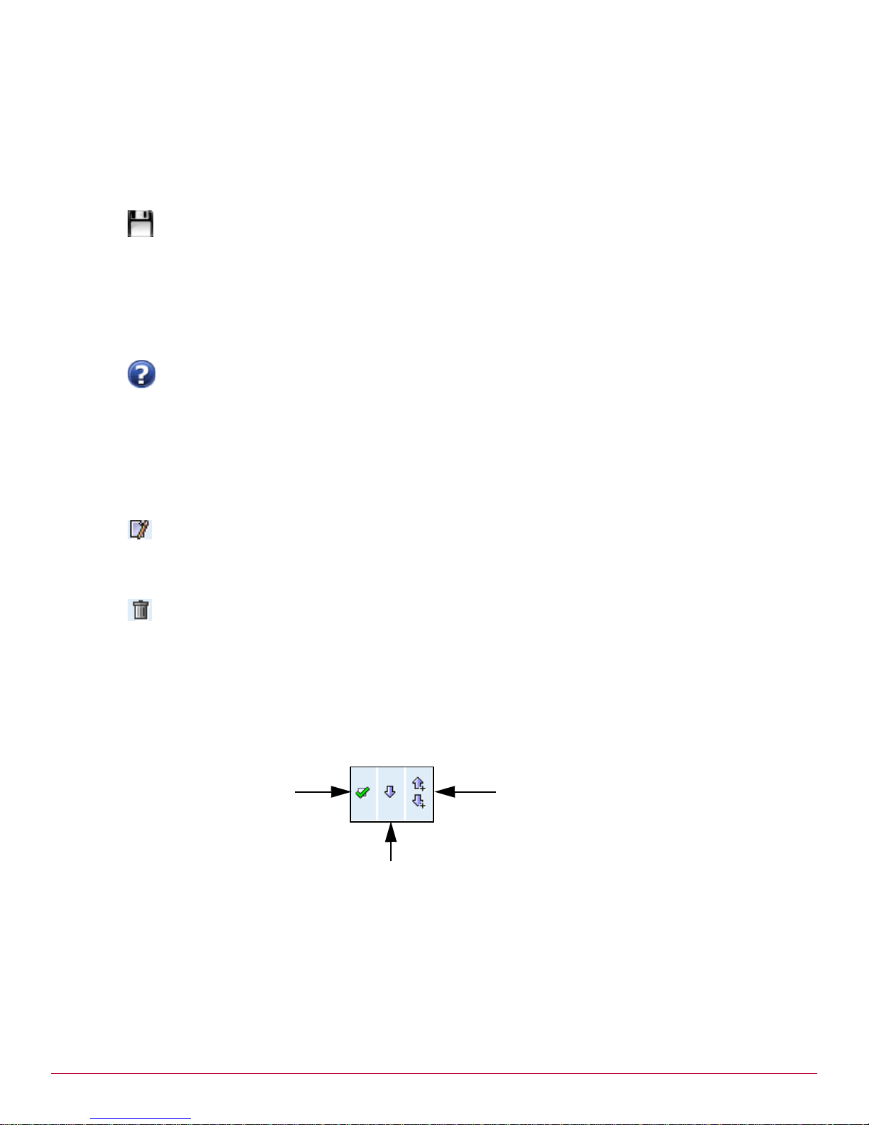
Add above and below icons
Certain pages within the Web console, see packet filtering and NAT rules for example, have icons you can
use to add and manipulate the ordered list of objects within the pages.
The controls you use to manipulate rules (and policy routes as well) are labelled in Figure 11.
Figure 11 Rule object controls
The add above or below icon has plus (+) signs next to the arrows, indicating you are adding an object. The
arrow pointing upward adds the object above the current row selection; the arrow pointing downward adds
the object below the current row.
Many of the pages in the console also have enable or disable checkboxes. The enable checkbox is the
leftmost checkbox.
20 McAfee UTM Firewall 4.0.4 Administration Guide
Tooltips
Hover your pointer over a control to view its tooltip (Figure 12).
Page 21

Introduction
Help and Support menu option
Figure 12 Tooltip
Help and Support menu option
The Help and Support menu option provides access to the following pages:
• Online Help page
• Technical Support page
• Technical Support Report page
Online Help page
This page provides information about and access to the UTM Firewall online help. To go to the Online Help
page, from the System menu, click Help and Support. The Help tab appears (Figure 13).
Figure 13 Online Help Search page
To access context-sensitive help for the page your are currently viewing, click the help icon in the upper
right corner of the page. Help describes each field and provides acceptable input values where appropriate.
To search the entire help system, enter terms in the Keywords field and click Search. The search results
are displayed in the page. Click a link to view its associated topic. The Search field is available on every
help page.
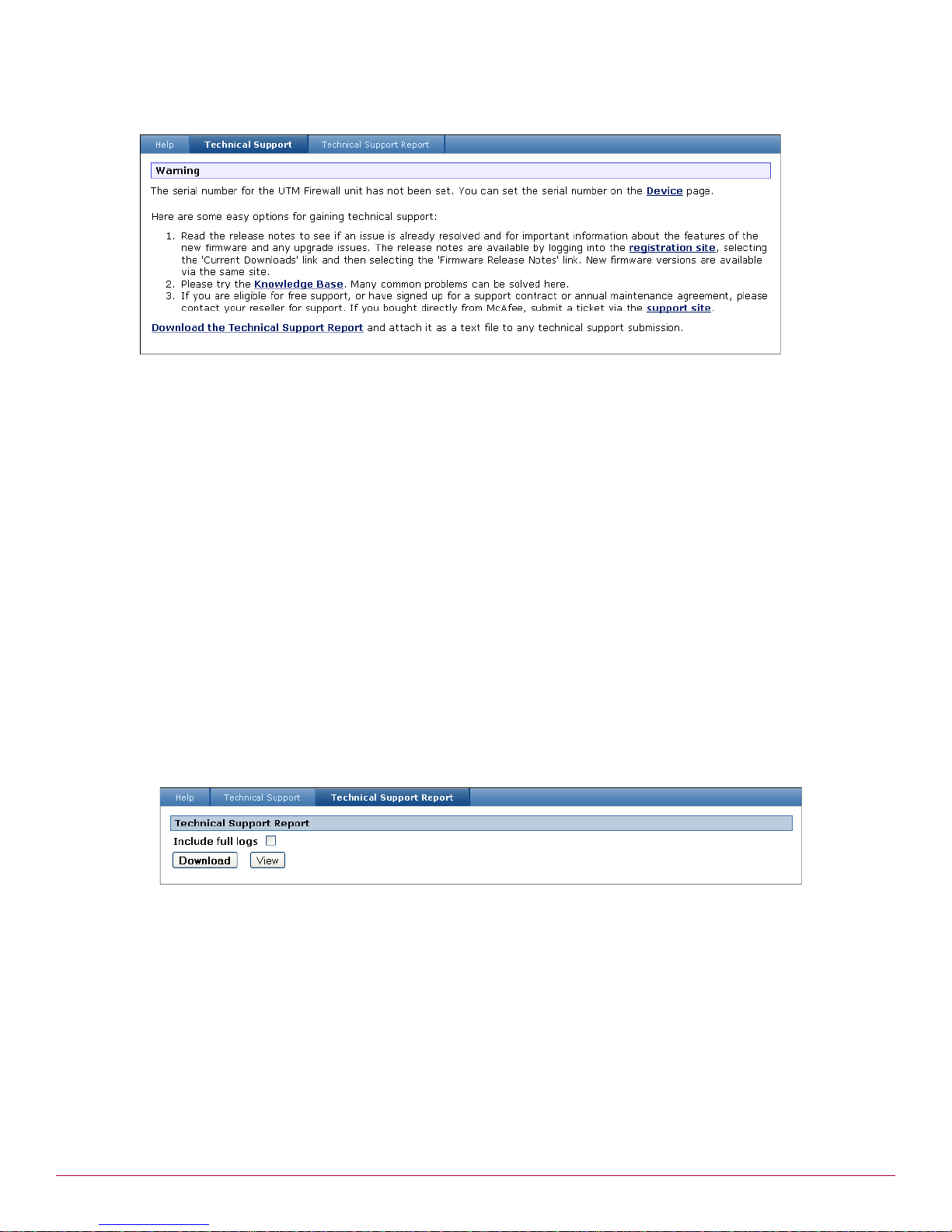
Technical Support page
To access the technical support page, from the System menu, click Help and Support, then select the
Technical Support tab. The Technical Support page appears (Figure 14).
McAfee UTM Firewall 4.0.4 Administration Guide 21
Page 22
Introduction
Help and Support menu option
Figure 14 Technical Support page
a
This page provides information about the firmware release notes, links to the Knowledge Base and the
Support site, and a link that allows you to download the technical support report. The technical support
report is used to assist technical support staff with troubleshooting the configuration of your appliance.
When contacting Support, you should always download and attach a technical support report. See Technical
Support Report page for details.
Technical Support Report page
The Technical Support Report page is an important and invaluable resource for the technical support team
to use to analyze issues with your UTM Firewall applia nce. If you experience an issue with your appliance,
and you need to contact the technical support team, always include the technical support report with your
support request. Without this report, the technical support staff are unlikely to have enough information to
assist you.
Security Alert: To maintain your security and privacy, the technical support report removes any confidential
information such as passwords and keys.
Tip: The technical support report should be generated when t he issue is occurring. It should also be generated on
each of the appliances involved, and attached to the support request in plain text format.
To generate a technical support report:
1 From the System menu, click Help and Support, and then select the Technical Support Report tab.
The Technical Support Report page appears (Figure 15).
Figure 15 Technical Support Report page
[Optional] Select the Include full logs checkbox if you want to include all log entries in the Technical
2
Support Report. Otherwise, only the most recent log entries will be included.
3 Click Download.
4 Save the report as a text file.
5 Submit a support request and attach the technical support report in plain text format.
22 McAfee UTM Firewall 4.0.4 Administration Guide
Page 23

Getting Started
2
Contents
Overview
Powering on the device
Connecting an administrative PC to the device
Connect your administrative PC to the device:
Configuring the UTM Firewall switch
Confirming settings
Setting up the PCs on your LAN
Registering your UTM Firewall
Overview
This chapter walks you through the installation of your McAfee UTM Firewall device. These instructions
apply to the SG310, SG560U, SG565, SG580, and SG720 models. For instructions on installing an SG640,
refer to the McAfee UTM Firewall Quick Installation Guide for PCI Cards. Installing the UTM Firewall into a
well-planned network is quick and easy. To add your UTM Firewall device to your LAN (Local Area Network),
perform the following procedures:
1 Powering on the device
2 Connecting an administrative PC to the device
3 Configuring the UTM Firewall switch
4 Confirming settings
5 Setting up the PCs on your LAN
6 Registering your UTM Firewall
Note: These procedures assume you have a PC running Microsoft Windows (2000 or later) with an Ethernet
network interface card installed. You may need to be logged in with administrator privileges.
Powering on the device
Connect the power adapter to the device and apply the power. Use only the power adapter packaged with
the unit.
Check that the front panel System/Heart Beat (H/B) /TST lights, along with all other front panel LEDs,
flash when the device is running.
Note: If these LEDs do not behave in the above manner before your device is attached to the network, perform a
factory reset. Press the erase button on rear panel twice within three seconds, 1 second apart to restore factory
default settings. If the LEDs are still not flashing after 30 seconds, you may need to contact customer service.
McAfee UTM Firewall 4.0.4 Administration Guide 23
Page 24

Getting Started
Connecting an administrative PC to the device
Connecting an administrative PC to the device
1 Connect your administrative PC to the device:
• If you are setting up the SG310, attach your PC's network interface card directly to any LAN port on
the device using the supplied network cable.
• If you are setting up the SG560, SG560U, SG565 or SG580, attach your PC's network interface card
directly to any network port on switch A (A1 - A4) using the supplied network cable.
2 Launch your Web browser. At setup, the UTM Firewall device has an internal DHCP server option that
automatically resolves any DNS request with the UTM Firewall device’s own LAN IP address.
The UTM Firewall Quick Setup Wizard appears with the Set Adminis tra ti on Pa ss word dialo g sh owi ng.
Note: If the UTM Firewall Management Cons ole does not automatically appear (perhaps because yo u h a v e n o
home page established on your browser), navigate to
Firewall device at
erase button on the unit's rear panel twice within 3 seconds, 1 second apart. Wait 20 - 30 seconds, and then
try browsing to
192.168.0.1, or are not accepted, reset the device to the factory default by pressing the
192.168.0.1 again.
192.168.0.1. If you are unable to browse to the UTM
Setting password and LAN connection settings
1 Enter and confirm a new password for your UTM Firewall. This is the password for the user root, the main
administrative user account on the UTM Firewall. It is important to choose a password that is hard for
others to guess, and to keep the password safe.
The new password takes effect immediately. You are prompted to enter the new password wh en
completing the next step.
Click Submit. A logon prompt is displayed (Figure 16).
Figure 16 Logon prompt
2
Enter the user name root, and the password you created in Step 1.
Click OK. The Hostname dialog appears (Figure 17).
24 McAfee UTM Firewall 4.0.4 Administration Guide
Page 25
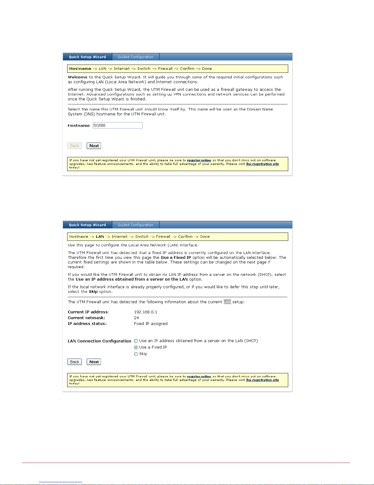
Getting Started
Setting password and LAN connection settings
Figure 17 Quick Setup Wizard – Hostname dialog
.
3 Enter a Hostname to identify the device. The name must begin with an alpha character, and can consist
of number letters and dashes. The default is the model number.
Click Next. The LAN dialog appears (Figure 18).
Figure 18 Quick Setup Wizard – LAN dialog
4
Select an option for your LAN configuration:
•[Recommended] To manually configure your LAN and optionally enable the UTM Firewall’s built-in
DHCP server, which automatically configures the network settings of PCs and other hosts on your LAN,
select Use a fixed IP.
• To use the UTM Firewall’s initial network settings as a basis for your LAN settings, and not use the UTM
Firewall's built-in DHCP server, select Skip.
McAfee UTM Firewall 4.0.4 Administration Guide 25
Page 26
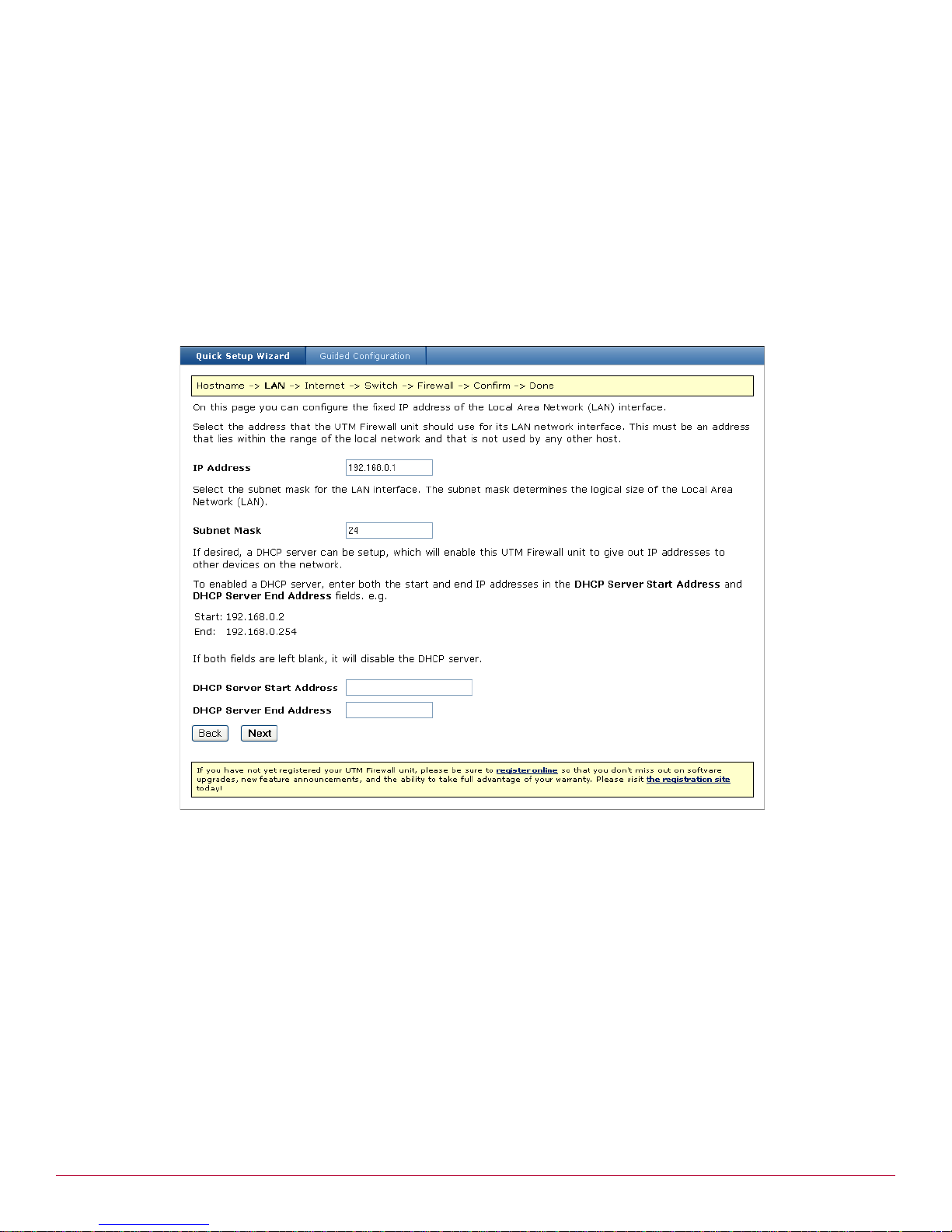
Getting Started
Setting password and LAN connection settings
•[Not recommended] If you have an existing DHCP server, and want to rely on the DHCP server to
automatically configure the UTM Firewall's LAN connection setting, choose Use an IP address from
a server on the LAN (DHCP).
Note: Changes to the UTM Firewall's LAN configuration do not take effect until you complete the quick setup
wizard.
Click Next.
• If you did not select Use a fixed IP configuration, skip to Step 6 on page 27.
• If you selected Use a fixed IP, the fixed IP configuration dialog appears (Figure 19). Continue to
Step 6 on page 27.
Figure 19 Quick Setup Wizard – fixed IP configuration dialog
.
5 Enter an IP address and Subnet Mask for the UTM Firewall's LAN connection. Take note of the IP
address and subnet mask; you will need them later on.
To enable the UTM Firewall's built-in DHCP serv er, en ter bo th the st ar t and en d IP a ddr ess es o f a
range of addresses in the DHCP Server Start and End Address fields. PCs and other hosts on your
LAN set to automatically obtain network settings are assigned an address from this range, and use the
UTM Firewall as their gateway to the Internet, and as their DNS s erver for Inter net domai n nam e
resolution.
Or, if you plan to use a DHCP server already on you r LAN, le ave the field blank to leave the UTM
Firewall’s DHCP server disabled.
Click Next.
• If you are not configuring an SG565, The ISP connection dialog appears (Figure 20).Continue to Step 6
on page 27.
• If you are configuring an SG565, the Wireless dialog appears. See Wireless for configuration details,
and then continue to Step 6 on page 27.
26 McAfee UTM Firewall 4.0.4 Administration Guide
Page 27
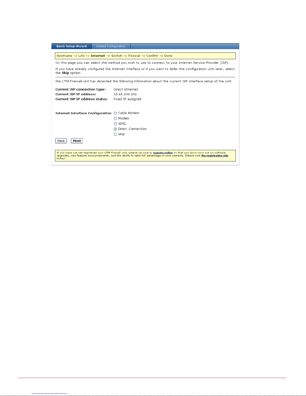
Getting Started
Setting password and LAN connection settings
Figure 20 Quick Setup Wizard – ISP connection dialog
.
6 Select an option for your Internet Interface Configuration:
•Select Cable Modem if connecting using a cable modem.
•Select Modem if connecting using a regular analog modem.
•Select ADSL to attempt automatic detection of your ADSL connection type if connecting using an ADSL
modem.
•Select Direct Connection if you have a direct connection to the Internet (e.g., a leased line).
•Select Skip if your Internet connection is already configured, or you want to defer its configuration.
7 Click Next. The page that appears depends on the selection you made on the ISP Connection page:
• If you selected Cable Modem, see Connecting with a cable modem for configuration details.
•If you selected Modem, see Configuring a dialout connection on the COM port for configuration details.
• If you selected ADSL, see ADSL for configuration details.
The next dialog that appears depends on the UTM Firewall model you are setting up.
• If you are setting up an SG310, the Firewall page appears. Go to Selecting an initial firewall level.
• For all other models, the Switch Configuration page appears. Go to Configuring the UTM Firewall
switch.
• If you selected Skip, the next page that appears depends on the UTM Firewall model you are setting
up.
• If you are setting up an SG310, the Firewall page appears. Go to Selecting an initial firewall level.
• For all other desktop models, the Switch Configuration page appears. Go to Configuring the UTM
Firewall switch.
• If you selected Direct Connection, the direct connection dialog for choosing a dynamic or static
Internet interface appears (Figure 21). Continue to Step 8 on page 28.
McAfee UTM Firewall 4.0.4 Administration Guide 27
Page 28
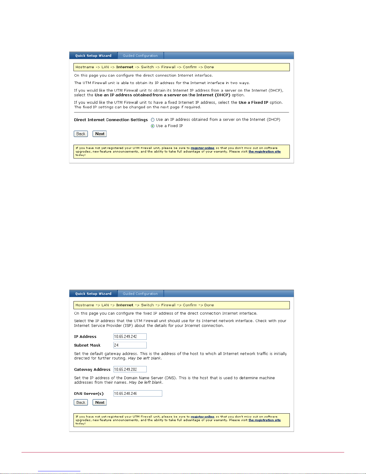
Getting Started
Setting password and LAN connection settings
Figure 21 Quick Setup Wizard – direct connection dialog
.
8 Select an option for the ISP connection.
•Select Use an IP address obtained from a server on the Internet (DHCP) if you plan to use a
DHCP server already in use on your LAN.
• [Recommended] Select Use a Fixed IP to manually configure the Internet address using static
parameters.
9 Click Next.
•If you chose Use an IP address obtained from a server on the Internet (DHCP), and you are
setting up an SG310, the Firewall page appears. Continue to Selecting an initial firewall level.
• For all other desktop models, the Switch Configuration page appears. Go to Configuring the UTM
Firewall switch.
•If you chose Use a Fixed IP, the direct connection page appears for configuring the Internet interface
(Figure 22).
Figure 22 Quick Setup Wizard – direct connection Internet interface dialog
.
28 McAfee UTM Firewall 4.0.4 Administration Guide
Page 29
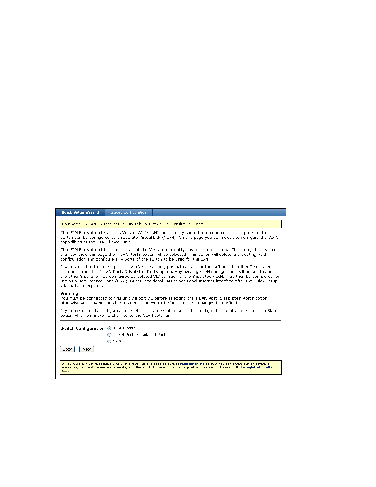
Getting Started
Configuring the UTM Firewall switch
10Fill out the fields:
•In the IP Address field, enter the static IP address you want to apply to the WAN port of the appliance.
•Enter the Subnet Mask to use for the WAN port.
• [Optional] Set the default Gateway Address.
• [Optional] Set the IP address of the Domain Name Server (DNS).
11Click Next.
• The Switch Configuration page appears for most models. In this case, go to Configuring the UTM
Firewall switch.
• If you are setting up a SG310, the Confirm Settings page appears. Go to Confirming settings.
Configuring the UTM Firewall switch
The switch dialog displays if you are setting up the SG560, SG 560U, SG565 or SG580. If you are setting
up a different model, skip to Selecting an initial firewall level.
By default, the UTM Firewall's switch A behaves as a conventional switching hub. However, it may be
configured so that each port behaves as if it were physically separate from the others.
Figure 23 Quick Setup Wizard – Switch dialog
.
1 Select a configuration for the UTM Firewall's switch (Figure 23).
• If you require multiple network segments, such as a DMZ, guest network, or second LAN; or if you
want to use multiple broadband Internet connections for Internet load balancing or Internet failover,
select 1 LAN Port, 3 Isolated Ports. Port A1 is used as the primary LAN connection.
• Otherwise, select 4 LAN Ports.
2 Click Next. The Firewall dialog appears (Figure 24).
McAfee UTM Firewall 4.0.4 Administration Guide 29
Page 30
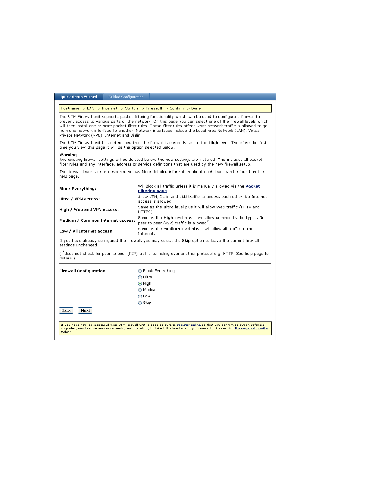
Getting Started
Selecting an initial firewall level
Selecting an initial firewall level
UTM Firewall devices support packet filtering rules that can be used to restrict access to parts of your
network. The firewall dialog enables you to select a firewall level, and have the associated packet filtering
rules applied automatically. See Packet filtering.
Figure 24 Quick Setup Wizard – Firewall dialog
1
Select a Firewall Configuration option (Figure 24).
• Block Everything – Blocks all traffic that is not expressly allowed by a packet filtering rule.
• Ultra / VPN access – Allows VPN, Dialin and LAN traffic to move through the firewall. Denies all
Internet traffic
• High / Web and VPN access – Allows VPN, Dialin, LAN, HTTP and HTTPS traffic to move through the
firewall. Denies other common traffic types.
• Medium / Common Internet access – Allows VPN, Dialin, LAN, HTTP, HTTPS, and most common
types of traffic to move through the firewall. Denies peer to peer (P2P) traffic unless that traffic is
tunneled through another protocol (such as P2P over HTTP).
• Low / All Internet access – Allows all Internet traffic to pass through the firewall.
2 Click Next. The Confirm settings dialog appears.
30 McAfee UTM Firewall 4.0.4 Administration Guide
Page 31

Getting Started
Confirming settings
Confirming settings
Review your configuration selections. If you are satisfied with your settings, click Finish to activate the
new configuration (Figure 25).
Figure 25 Quick Setup Wizard – Confirmation dialog
.
Note: If you changed the UTM Fi rewall's LAN connection settings, you may not be able to contact it at this point.
The following describes how to set up the PCs on your network to access the device and the Internet.
If you have not already done so, connect the device to your LAN:
• If you are setting up the SG310, connect PCs and/or your LAN hub directly to its LAN switch.
• If you are setting up the SG560, SG560U, SG565 or SG580 and have configured its switch as 4 LAN
Ports, connect PCs and/or your LAN hub directly to switch A.
• If you are setting up the SG560, SG560U, SG565 or SG580 and have configured its switch as 1 LAN
Port, 3 Isolated Ports, connect port A1 directly to your LAN hub.
• Otherwise, connect the LAN port directly to your LAN hub.
Setting up the PCs on your LAN
Each PC on your LAN must now be assigned an appropriate IP address, and have the UTM Firewall's LAN IP
address designated as its gateway and DNS server. A DHCP server allows PCs to automatically obtain these
network settings when they start up. If your network does not have a DHCP server, you may either
manually set up each PC on your network, or set up the UTM Firewall's DHCP server.
• [Recommended] To use the UTM Firewall's built-in DHCP server, proceed to Automatic LAN configuration
using an existing DHCP server.
• If your LAN already has a DHCP server you will use instead of the UTM Firewall's built-in DHCP server,
proceed to Automatic LAN configuration using an existing DHCP server.
McAfee UTM Firewall 4.0.4 Administration Guide 31
Page 32

Getting Started
Setting up the PCs on your LAN
• If you do not want to use a DHCP server, proceed to Manual LAN configuration.
Automatic LAN configuration using the UTM Firewall DHCP server
By selecting Manual Configuration for the UTM Firewall's LAN connection, and supplying the DHCP Server
Address Range, the UTM Firewall's DHCP server is already set up and running. Each PC on your LAN must
now be set up to automatically obtain network settings.
1 Click Start > Settings > Control Panel and double-click Network Connections. If presented with
multiple connections, right-click Local Area Connection (or appropriate network connection) and click
Properties.
2 Select Internet Protocol (TCP/IP) and click Properties (Figure 26).
Figure 26 Internet Protocol (TCP/IP) Properties
3
Click Obtain an IP address automatically.
4 Click Obtain DNS server address automatically.
5 Click OK.
Automatic LAN configuration using an existing DHCP server
If you chose the Obtain LAN IP address from a DHCP server on LAN option, we strongly recommend
that you add a lease to your existing DHCP server to reserve the IP address you chose for the UTM
Firewall's LAN connection.
If you chose to set the UTM Firewall's LAN connection settings using Manual configuration, remove this
address from the pool of available addresses, then:
1 Enter this same IP address as the gateway IP address for the existing DHCP server to hand out.
2 Enter this same IP address as the DNS server IP address for the DHCP server to hand out.
3 Ensure all PCs on the network are set up to automatically obtain network configuration as per Automatic
LAN configuration using the UTM Firewall DHCP server, then restart them.
Note: The purpose of restarting the computers is to force an update of their automatically configured network
settings. Alternatively, you can disable and re-enable the network connection.
32 McAfee UTM Firewall 4.0.4 Administration Guide
Page 33

Getting Started
Registering your UTM Firewall
Manual LAN configuration
Click Start > Settings > Control Panel, and then double-click Network Connections. If presented with
multiple connections, right-click on Local Area Connection (or appropriate network connection) and
select Properties.
1 Select Internet Protocol (TCP/IP).
2 Click Properties.
3 Enter the following details:
• IP address – An IP address that is part of the same subnet range as the UTM Firewall's LAN connection
(for example, if using the default settings, 192.168.0.2 - 192.168.0.254).
• Subnet mask – Subnet mask of the UTM Firewall's LAN connection (if using the default settings,
255.255.255.0).
• Default gateway – IP address of the UTM Firewall's LAN connection (if using the default settings,
192.168.0.1).
• Preferred DNS server – IP address of the UTM Firewall's LAN connection (if using the default
settings, 192.168.0.1).
4 Click OK. Repeat for each PC on your network.
Quick setup is now complete. Quick setup is all you need to do to get basic network connectivity to the
Internet. Network devices on the LAN should now be able to access the Internet in accordance with the
settings you have configured, and provided that all physical network connections are in place.
Registering your UTM Firewall
You must register your UTM Firewall device in order to receive technical support. A current email address is
required to register your product. Registering online allows you to keep abreast of firmware updates and to
take advantage of your warranty.
The Quick Setup page provides links to the product registration site. You can register your product either
before or after completing the Quick Setup Wizard. If you choose to register later, browse to:
http://my.securecomputing.com, or use the registration links available on Technical Support tab
(Figure 27).
The Technical Support tab is available from every user page by selecting the Help button on the user page,
then selecting the Technical Support tab (Figure 27).
Figure 27 Technical Support tab
McAfee UTM Firewall 4.0.4 Administration Guide 33
Page 34

Getting Started
Registering your UTM Firewall
Using the My Secure Computing website
The My Secure Computing website allows you to track your products, activate features, and access
firmware upgrades. You can access the site by either clicking one of the registration site links in the Quick
Setup Wizard or on the Help and Support page, or by navigating to http://my.securecomputing.com.
You will be prompted to provide your email address and password (Figure 28).
Figure 28 My Secure Computing Login page
Creating an account
If you have not already done so, you will need to create a My Secure Computing account to access the site.
To create an account:
34 McAfee UTM Firewall 4.0.4 Administration Guide
Page 35

Getting Started
Registering your UTM Firewall
1 From the My Secure Computing Login page, select Click here if you need to create a new account.
The My Secure Computing New Account Request appears (Figure 29).
Figure 29 My Secure Computing New Account Request page
2
Enter your E-mail address and click Create Account. A message indicates a new account request is
currently being processed. Upon verification, a login password is emailed to you.
Once you log in, you can change your My Secure Computing password, add pro ducts you own to your
profile, download Beta firmware, and activate any add-on features you may have purchased.
Adding your UTM Firewall appliance
To add a product you have purchased to your My Secure Computing profile:
McAfee UTM Firewall 4.0.4 Administration Guide 35
Page 36

Getting Started
Registering your UTM Firewall
1 Log in to the My Secure Computing site at http://my.securecomputing.com. The Welcome page appears
(Figure 30).
Figure 30 My Secure Computing Welcome page
2
Click Add Products. The Product Management - Add Device page appears (Figure 31).
36 McAfee UTM Firewall 4.0.4 Administration Guide
Page 37

Getting Started
Registering your UTM Firewall
Figure 31 My Secure Computing Product Management — Add Device page
Enter the serial number of your UTM Firewall appliance in the McAfee UTM Firewall Serial Number field.
3
The serial number is found on a sticker attached underneath the appliance.
4 Indicate the Year and Month for Date of Purchase.
5 Click Submit. To view a list of all products you have registered, click List Products.
Activating a feature
Use this procedure to activate an add-on feature such as Web Filtering. Make sure you have registered your
appliance and have the token provided to you for the feature.
1 Log in to the My Secure Computing site at http://my.securecomputing.com.
2 Click Activate Features. The Product Management - Activate Feature page appears (Figure 32).
McAfee UTM Firewall 4.0.4 Administration Guide 37
Page 38

Getting Started
Registering your UTM Firewall
Figure 32 My Secure Computing Product Management — Activate Feature page
3
Select your UTM Firewall appliance from the SnapGear Serial Number list.
4 Enter the token in the Feature Serial Number (token) field.
5 Click Submit.
Retrieving license information for add-on products
Once you activate a feature, that feature is added to the Options and Expiration Dates box on the Product
Management page (Figure 33).
38 McAfee UTM Firewall 4.0.4 Administration Guide
Page 39

Getting Started
Registering your UTM Firewall
Figure 33 My Secure Computing Product Management - License data
For those features that require a certificate and private key to activate, click the associated View...
License data button. The certificate and private key are then displayed in text form (Figure 34).
McAfee UTM Firewall 4.0.4 Administration Guide 39
Page 40

Getting Started
Registering your UTM Firewall
Figure 34 Product Management - License details
You can then copy and paste the license key, for Web Filtering for instance, into the Certificate copy/paste
page.
Note: Be sure to include the ----Begin... and ----End... text lines in you r copy and paste.
40 McAfee UTM Firewall 4.0.4 Administration Guide
Page 41

3
Network Setup menu options
Contents
Network overview
Quick Setup wizard
Network setup
Multifunction vs. fixed-function ports
ADSL
Connecting with a cable modem
Configuring a dialout connection on the COM port
Setting up dial-in access
Failover, load balancing, and high availability
Internet connection failover
High Availability
DMZ network
Guest network
Wireless
Bridging
VLAN
3G USB Modems
Routes
DNS
DHCP Server
Web cache
Traffic Shaping
IPv6
SIP
Network overview
This chapter describes the Network Setup options of the McAfee UTM Firewall Management Console. Use
the Network Setup options to configure each of your UTM Firewall appliance’s Ethernet, wireless, and serial
ports.
• An Ethernet network interface can be configured to connect to your LAN, DMZ, an untrusted LAN, or the
Internet as a primary, backup, or load-balancing connection.
• A serial port can be configured to provide remote dial-in access, or connect to the Internet as a primary
or back-up connection.
• A wireless interface can be configured to connect to your LAN, DMZ, or an untrusted LAN.
Instructions for configuring the PCs on your LAN can be found in Chapter 2, Getting Started.
McAfee UTM Firewall 4.0.4 Administration Guide 41
Page 42

Network Setup menu options
Quick Setup wizard
Quick Setup wizard
A Quick Setup wizard is provided to assist you in configuring your UTM Firewall device for the first time. The
Quick Setup wizard also provides Guided Configurations to assist you with some of the more complex
configuration scenarios. Using the Quick Start wizard is covered in the Quick Installation Guide that
accompanied your UTM Firewall device, and in Chapter 2, Getting Started, beginning with Connecting an
administrative PC to the device.
Network setup
The Network Setup tab provides options for configuring network connections, failover and high-availability
settings, routes, DNS proxies and IP protocol settings.
Multifunction vs. fixed-function ports
Some UTM Firewall appliances have network ports with labels corresponding to the port’s function, such as
LAN, DMZ, and Internet/WAN. These are said to be fixed-function ports.
Alternatively, some UTM Firewall appliances have network ports that are generically labeled; for example,
port A, port B, port C. These are said to be multifunction ports. This reflects the ability of these ports to
perform different functions; for example, port B is not limited to connecting to the Internet only, it can be
configured as a LAN connection. Before configuring multifunction ports, determine which function you are
assigning to each of the ports.
The SG560, SG560U, SG565, and SG580 models have generically named Ethernet ports (ports A1, A2, A3,
A4 and B). By default, switch A functions as a regular LAN switch, with network traffic passing freely
between its ports. Typically, port B is used as your primary Internet connection. However, switch A’s ports
can be configured individually to perform separate functions. For example, port A2 can be a configured to
connect to a second LAN, port A3 can be configured as a DMZ port, and port A4 can be configured as a
secondary Internet connection. These per-port configuration scenarios are accomplished using VLANs
(Virtual Local Area Networks). For information about the advanced use of the VLAN capability of your UTM
Firewall appliance, refer to VLAN and Port-Based VLANs.
Connections
Under the Connections tab, each of your UTM Firewall appliance’s network interfaces is displayed alongside
its physical Port name and the Current Details of its configuration (Figure 35).
Initially, all network interfaces are unconfigured, aside from a single LAN connection on the initial setup
port (Switch A on UTM Firewall appliances SG560, SG560U, SG565, and SG580; the LAN port on other
models).
This page displays a list of the physical and virtual network interfaces of the UTM Firewall unit, as well as
the network connections that have been configured for these interfaces.
Network interfaces can be physical interfaces such as Ethernet ports or serial ports. They can also be virtual
interfaces such as bridges, GRE tunnels, or VLANs.
To configure a network connection, you need to specify the configuration details that will enable the
network interface to be used for routing. The simplest network connections are static or dynamic IP
addresses. More advanced network connections allow you to communicate with cable, ADSL, or serial
modems that are connected to your UTM Firewall appliance.
42 McAfee UTM Firewall 4.0.4 Administration Guide
Page 43

Network Setup menu options
Network setup
Figure 35 Network Setup Connections page
A network interface is configured or changed by selecting a connection type from the Change Type list.
Click Retry to immediately retry any connections that are currently down or have completely failed.
You can create new virtual network interfaces by selecting an option from the list and clicking Add.
Viewing or editing a connection
The current configuration for a connection can be viewed or edited by clicking its edit icon.
1 From the Network Setup menu, click Network Setup. The Network Setup Connections tab appears.
2 Select the edit icon for the connection your want to edit. The main configuration page appropriate for the
connection appears.
3 Make your changes and click Update. You can also make changes in the additional tabs that appear for
a connection, such as Aliases and IPv6. For more information, see Aliases tab and Enabling IPv6 for a
connection.
Disabling a connection
1 From the Network Setup menu, click Network Setup. The Network Setup Connections tab appears.
2 Select the enable checkbox for the connection. There should be a check mark present.
3 You are prompted to confirm disabling the connection. Click OK. The check mark no longer appears in the
leftmost column.
Enabling a connection
Use this procedure to enable a disabled connection. A connection that can be re-enabled appears as an
empty checkbox in the leftmost column.
1 From the Network Setup menu, click Network Setup. The Network Setup Connections tab appears.
2 Select the checkbox for the connection. The Enable/Disable checkbox is to the left of the Name column.
The page refreshes and a check mark appears in the column (Figure 36).
Figure 36 Enabled and disabled connections
McAfee UTM Firewall 4.0.4 Administration Guide 43
Page 44

Network Setup menu options
Network setup
Deleting a connection
Use this procedure to delete a connection configuration for a network interface.
Note: You cannot delete the Direct Connection configuration for Switch A.
If you delete a port-based VLAN, any ports assigned to that VLAN revert to the default VLAN of the switch.
You can then reassign the port to a different VLAN using the VLAN Configuration tab of the VLAN. For
further information, see Editing a VLAN.
1 From the Network Setup menu, click Network Setup. The Network Setup Connections tab appears.
2 Select the delete icon for the connection your want to delete. You are prompted to confirm the delete.
Click OK.
3 If the connection was a virtual connection, the connection no longer appears in the Connections table.
Otherwise, the Change Type column displays Unconfigured in its configuration list.
Direct connection overview
A direct connection is a direct IP connection to a network that does not require a modem to be established.
This is typically a LAN, DMZ, or Guest connection, but it can also be an Internet connection. Network
settings can be assigned statically, or dynamically by a DHCP server.
Direct connections can be added to a network bridge. For more information, see Bridging.
Direct Connection Settings page
Use this page to configure IP address settings for a direct connection.
1 From the Network Setup menu, click Network Setup. The Network Setup Connections tab appears.
2 Select the edit icon for the connection your want to edit. The main configuration page appropriate for the
connection appears.
3 Click the Direct Connection tab. The Direct Connection Settings page appears (Figure 37).
Figure 37 Direct Connection page
[Optional] Enter a descriptive name for the interface in the Connection Name field.
4
5 Perform one of the following options:
• If you are using DHCP, select the DHCP assigned checkbox and skip to Step 8. The appliance obtains
its LAN network settings from an active DHCP server on your local network. Any values in the IP
Address, Subnet Mask, and Gateway fields are ignored.
44 McAfee UTM Firewall 4.0.4 Administration Guide
Page 45

Network Setup menu options
Network setup
• If you are defining a static address, clear the checkbox and continue with the next step. You must
define the IP address and Subnet Mask.
6 To assign network settings statically, enter an address in the IP Address field. If you are using the UTM
Firewall appliance in its default network address translation mode, this is typically part of a private IP
address range, such as 192.168.0.1 / 255.255.255.0.
7 Enter the subnet mask you want to use for this port in the Subnet Mask field.
Range: 0-32; can also be in the form 255.255.255.0
8 If required, enter the IP address of the default Gateway out which to send outgoing traffic on this
connection. If the default gateway is via the DMZ, define this setting. For LAN connections, a default
gateway is not generally necessary.
9 [Conditional, if not using DHCP. Optional if using DHCP.] Enter one or more DNS servers the appliance
uses for DNS resolution in the DNS Servers field. To enter multiple servers, separate each IP address
with a comma. Any DNS server addresses allocated by the DHCP server take precedence over entries in
this field.
10Select a classification from the Firewall Class list. The Firewall class setting controls the basic allow/deny
policy for this interface. Allowed network traffic is accepted, denied network traffic is dropped. Dropped
means network traffic is denied silently; no response such as “connection refused” is sent back to the
originator of the traffic.
The policy associated with each firewall class is detailed in Table 10. VPN and Dial-In connections are
assigned a firewall class of LAN by default.
Table 10 Firewall class policy
Incoming Interface Outgoing Interface Action
LAN Any Accept
DMZ Internet Accept
DMZ Any except Internet Drop
Internet Any Drop
Guest Any Drop
For further discussion of DMZ and Gu es t networks , s ee DMZ network and Guest network.
11[Optional] Select the Preferred Gateway checkbox to enable traffic to be load-balanced across this
connection.
12Click Update.
Ethernet Configuration tab
Use this procedure to modify the low-level Ethernet configuration settings of an Ethernet network port.
1 From the Network Setup menu, click Network Setup. The Network Setup Connections tab appears.
2 Select the edit icon for the connection your want to edit. The main configuration page appropriate for the
connection appears.
3 Click the Ethernet configuration tab. The Configure Ethernet Port page appears (Figure 38).
McAfee UTM Firewall 4.0.4 Administration Guide 45
Page 46

Network Setup menu options
Network setup
Figure 38 Configure Ethernet Port
4
On rare occasions, it may be necessary to change the Ethernet hardware or MAC Address of your UTM
Firewall appliance. The MAC address is a globally unique address and is specific to a single UTM Firewall
appliance. It is set by the manufacturer and should not normally be changed. However, you may need to
change it if your ISP has configured your ADSL or cable modem to only communicate with a device with
a known MAC address.
Enter a MAC address in the MAC field. The address can be an Ethernet MAC address of the form
AA:BB:CC:DD:EE:FF, where each of the components is a hexadecimal digit.
Note: This setting cannot be changed for the LAN port or Port A.
5 [Optional] If an Ethernet port is experiencing difficulties auto-negotiating with another device, you can
manually set Ethernet speed and duplex from the Ethernet Speed list. Available options are:
• Default Auto Negotiation
• 100 Base Tx - Auto Duplex
• 100 Base Tx - Full Dupl ex
• 100 Base Tx - Half Duplex
• 10 BaseT - Auto Duplex
• 10 BaseT - Full Duplex
• 10 BaseT - Half Duplex
•100 Base T4
6 Specify the MTU (Maximum Transmission Unit) for the interface in the MTU field. This setting should
normally be left at 1500. The value can be an integer equal to or greater than 1.
Note: This setting only effects the Ethernet interface, and does not change the MTU for ADSL PPPoE interfaces.
7 [Optional. Models SG560, SG560U, SG565, or SG580 only.] To enable the VLANs of the switch, select the
Enable Port-based VLANs checkbox. When enabled, each port in the switch can be assigned to
different VLANs. The primary reason for using port-based VLANs is to isolate each port in the switch. This
allows you to connect different networks to each port, and to enforce firewall policies between ports. After
enabling port-based VLANs, you need to create VLANs on the Connections page, modify the VLANs, and
assign ports to each VLAN on the VLAN Configuration tab. Any ports that are left unassigned will use the
default VLAN as described below. Port 1 will always use the default VLAN. You can also use the Quick
Setup Wizard to automatically create separate VLANs for each port. After disabling port-based VLANs, any
VLANs you have created will remain as tagged VLANs. You should delete them if they are unneeded.
46 McAfee UTM Firewall 4.0.4 Administration Guide
Page 47

Network Setup menu options
Network setup
8 [Conditional. Models SG560, SG560U, SG565, or SG580 only.] Specify the default VLAN ID for this switch
in the Default Port-based VLAN ID field. This field is only required when port-based VLANs are
enabled, and must be unique amongst the VLANs on this switch. If a port is disabled for all VLANs, then
the port will be set to untagged mode for the default VLAN. The untagged mode means the VLAN ID will
only be used while routing packets within this appliance. Devices connected to ports on the default VLAN
will not see the VLAN ID on the packet, and do not need to support VLANs. Therefore the actual value is
irrelevant, as long as it is unique.
• Range: 1-4094
• Can be blank
• Must be unique
9 Click Update.
Aliases tab
Alias addresses are typically assigned to an Internet network connection. Alias addresses enable you to use
the same TCP or UDP port for multiple servers. Interface aliases allow the UTM Firewall appliance to
respond to multiple IP addresses on a single network interface. This is useful for when your ISP has
assigned you a range of IP addresses to use with your Internet connection, or when you have more than
one subnet connected to a single network interface.
Figure 39 Aliases tab
For aliases on interfaces that have the DMZ or Internet firewall class, you must also setup appropriate
packet filtering or port forwarding rules to allow traffic on these ports to be passed from the alias address to
servers on the local network. For details, see Packet filtering and About port forwarding.
Adding an alias IP address for an interface
1 From the Network Setup menu, click Network Setup. The Network Setup Connections tab appears.
2 Select the edit icon for the connection your want to edit. The main configuration page appropriate for the
connection appears.
3 Click the Aliases tab (Figure 39).
4 Enter the alias address in the Alias IP Address field.
5 Enter the alias subnet mask in the Alias Subnet Mask field. Range: 0-32; can also be in the form
255.255.255.0
6 Click Add. The alias is added to the list of for the interface.
Deleting an alias IP address for an interface
1 From the Network Setup menu, click Network Setup. The Network Setup Connections tab appears.
2 Select the edit icon for the connection your want to edit. The main configuration page appropriate for the
connection appears.
McAfee UTM Firewall 4.0.4 Administration Guide 47
Page 48

Network Setup menu options
ADSL
3 Click the Aliases tab.
4 Click the delete icon for the alias IP address you want to delete. The alias is deleted from the list.
Enabling IPv6 for a connection
Use this procedure to enable IPv6 for a connection. In particular, enable IPv6 for the LAN connections on
which you want to advertise routes, and on the Internet connections on which you want to create 6to4
tunnels.
To route and filter IPv6 traffic, you must also enable IPv6 at the appliance level. For details, refer to IPv6
and Enabling IPv6 at the appliance level.
1 From the Network Setup menu, click Network Setup. The Network Setup Connections tab appears.
2 Select the edit icon for the connection your want to edit. The main configuration page appropriate for the
connection appears.
3 Click the IPv6 tab (Figure 40).
Figure 40 IPv6 connection level
ADSL
4
Select the Enable IPv6 checkbox.
5 [LAN connections only] You can enter a site level aggregation value for this connection in the Site Level
Aggregation field. This field is used to create a site-local address for this connection, and is also used
for creating routes for any 6to4 tunnels. This setting should be unique.
• Can be from 1 to 4 hexadecimal characters (0-9, a-b, A-B)
•Default: 0
6 Click Update.
Disabling IPv6 for a connection
Use this procedure to disable IPv6 for a connection. If you want to disable IPv6 for all connections, disable
IPv6 at the appliance level. For more information, see Disabling IPv6.
1 From the Network Setup menu, click Network Setup. The Network Setup Connections tab appears.
2 Select the edit icon for the connection your want to edit. The main configuration page appropriate for the
connection appears.
3 Click the IPv6 tab.
4 Clear the Enable IPv6 checkbox.
5 Click Update.
This topic contains procedures for configuring your DSL connection, also referred to as ADSL (Asymmetric
Digital Subscriber Line). ADSL connections have the interface firewall class of Internet.
48 McAfee UTM Firewall 4.0.4 Administration Guide
Page 49

Network Setup menu options
ADSL
Routed versus bridged DSL modems
Before you configure ADSL, check whether your DSL mode m is in a routed or bridged mode. Many ISPs
preconfigure this for your convenience. Often you can change the mode to suit your needs. Check with your
ISP to determine if they can accommodate changing between bridged and routed mode or vice versa on the
modem they supplied.
If your DSL modem is in routed mode, then all PPTP/PPPoE and similar login and connection considerations
are addressed from inside the modem. You should then connect your UTM Firewall appliance in Direct or
DHCP mode to your DSL modem, and will not be required to enter any additional ADSL information on the
UTM Firewall Management Console.
Note: Do not use ADSL configuration on the UTM Firewall Management Console if your modem is in routed mode.
There are some advantages to the bridged mode:
• Your UTM Firewall appliance becomes the portal to the Internet
• You do not have to port-forward service in two places (on the DSL modem and on the UTM Firewall
appliance).
The ADSL configurations listed here generally work best when your DSL modem is in bridged mode.
Note: PPPoA is not supported. If your ISP only supports PPPoA, the DSL modem must be configured in routed
mode.
If your ISP only support PPPoA, the UTM Firewall appliance needs to be configured with either DHCP or a
static address so it can communicate with the upstream router, which is your DSL modem.
ADSL configuration methods
You can configure DSL to establish a connection to your ISP using the following methods:
• Auto detect: If you are unsure of your ADS L connection type, the UTM Firewall appliance can attempt
to Auto detect ADSL connection type. The appliance is unable to detect the PPTP connection type. Refer
to the procedure Autodetecting your ADSL connection.
• PPPoE: Select this method if your ISP uses user name and password authentication to access the
Internet. Refer to the procedure Connecting ADSL via PPPoE.
• PPTP: Select this method if you have a dial-up VPN connection to the Internet provided by your ISP. Refer
to the procedure Connecting ADSL via PPTP.
• DHCP: Select this method if your ISP does not require a user name and password, or your ISP provides
a dynamic IP address. Refer to the procedure Connecting ADSL via DHCP.
• Manually Assign Settings: Select this method if your ISP has given you a static IP address or address
range. Refer to the procedure Manually assigning your ASDL settings.
Prerequisites
1 If you have not already done so, connect the appropriate network port of your UTM Firewall appliance to
your DSL modem.
2 Power on the DSL modem and give it some time to initialize. Ensure the Ethernet link LEDs are illuminated
on both the UTM Firewall appliance (if applicable to the model) and DSL modem. Do not continue until it
has reached the line sync state and is ready to connect. Most modems have a sync/line sync LED that
indicates whether or not the modem is talking to the DSLAM (Digital Subscriber Line Access Multiplexer)
of the telephone exchange. For more information on LEDs, refer to the appropriate LED topic for your UTM
Firewall model in Chapter 1, Introduction.
3 Access the ADSL connections page so that you can configure your DSL connection. See Accessing the
ADSL connection methods page.
McAfee UTM Firewall 4.0.4 Administration Guide 49
Page 50

Network Setup menu options
ADSL
Accessing the ADSL connection methods page
1 From the Network Setup menu, click Network Setup. The Connections page appears.
2 For the connection you want to configure ADSL on, select ADSL from the Change Type list. Not all
connections have this option available, such as the COM serial port. The ADSL tab opens and displays the
ADSL Connection Methods page (Figure 41).
Figure 41 ADSL Connection Methods
3
Select the connection method you need to use and click Next.
4 Continue with the procedure you need to use to connect:
• Autodetecting your ADSL connection
• Connecting ADSL via PPPoE
• Connecting ADSL via PPTP
• Connecting ADSL via DHCP
• Manually assigning your ASDL settings
Autodetecting your ADSL connection
Use this procedure to autodetect settings for your ADSL. Autodetect does not work for PPTP connections.
1 From the Network Setup menu, click Network Setup. On the Connections page, select ADSL from the
Change Type list. The ADSL Connection Methods page appears.
2 Select the Auto detect ADSL connection type option and click Next.
3 A message reminds you to hook up your equipment. Click Next.
4 Depending on what the appliance detects, either the ADSL DHCP Configuration page appears (see
Figure 44 on page 53), or the PPPoE page appears (Figure 42).
5 Complete the fields and click Finish.
If autodetect succeeds, additional configuration tabs appear, such as the VLAN configuration or Ethernet
configuration tab (depending on your connection type), Aliases, and IPv6. See Ethernet Configuration tab,
VLAN, Aliases tab, and Enabling IPv6 for a connection.
If autodetection fails, your DSL modem might not be configured correctly for your connection type, or your
DSL service has not yet been provisioned by your telecommunications company. Try the manual settings
procedure as well.
50 McAfee UTM Firewall 4.0.4 Administration Guide
Page 51

Network Setup menu options
ADSL
Connecting ADSL via PPPoE
Use this procedure to configure your ADSL for a PPPoE connection.
1 From the Network Setup menu, click Network Setup. On the Connections page, select ADSL from the
Change Type list. The ADSL Connection Methods page appears.
2 Select the Use PPPoE to connect option and click Next. The ADSL PPPoE Configuration page appears
(Figure 42).
Figure 42 ADSL PPPoE Configuration
[Optional] Enter a descriptive name in the Connection Name field.
3
4 Enter the username from your ISP in the Username field.
5 Enter the password from your ISP in the Password field.
6 Enter the password again in the Confirm Password field.
7 Select a classification from the Firewall Class list.
8 [Optional] Select the Preferred Gateway checkbox to enable load-balancing over this connection.
9 Click Finish.
By default, PPPoE connections are treated as always on and are kept up continuously. Alternatively, you
can choose to only bring the connection up when PCs on the LAN, DMZ, or Guest network (via a VPN
tunnel) are trying to reach the Internet. For instructions, refer to Enabling dial on demand for a connection.
Since DSL connections are not generally metered by time, this is rarely a desirable configuration due to the
delays when initiating the on-demand connection.
After you click Finish, additional configuration tabs appear, such as the VLAN configuration or Ethernet
configuration tab (depending on your connection type), Aliases, and IPv6. See Ethernet Configuration tab,
VLAN, Aliases tab, and Enabling IPv6 for a connection.
Connecting ADSL via PPTP
Use this procedure to configure a PPTP DSL connection to your ISP.
1 From the Network Setup menu, click Network Setup. On the Connections page, select ADSL from the
Change Type list. The ADSL Connection Methods page appears.
2 Select the Use PPTP to connect option and click Next. The ADSL PPTPoE Configuration page appears
(Figure 43).
McAfee UTM Firewall 4.0.4 Administration Guide 51
Page 52

Network Setup menu options
ADSL
Figure 43 ADSL PPTPoE Configuration
3
[Optional] Enter a descriptive name in the Connection Name field.
4 Enter the username from your ISP in the Username field.
5 Enter the password from your ISP in the Password field.
6 Enter the password again in the Confirm Password field.
7 Enter the enter the PPTP server address provided by your ISP in the PPTP Server IP Address field.
8 Enter a local IP address in the Local IP Address field. The local IP address is used on the UTM Firewall
appliance's network port through which you connect to the Internet.
Note: In general, this is not your actual Internet IP address, but is the IP address the PPTP client uses as its
source address. Once the PPTP client has established a connection with the ISP's PPTP server, the ISP allocates
an address that is used as the actual Internet interface on the UTM Firewall appliance. Usually the address
supplied by the ISP is different from the local IP address entered here. Even if the DSL modem is in bridged
mode, it typically has allocated an administrative IP address, such as 192.168.1.1 or similar, so the DSL
modem can be administered. It is recommended to set the local addres s to an IP on that same subnet, such as
192.168.1.2.
9 Enter the netmask for the UTM Firewall network port through which you are connecting to the Internet in
the Subnet Mask field. The netmask and the local address should be compatible with the LAN port
settings on the DSL modem.
10Select a classification from the Firewall Class list.
11[Optional] Select the Preferred Gateway checkbox to enable load-balancing over this connection.
12Select the strength of encryption from the Required Encryption Level drop-down menu. It is
recommended that Strong encryption be used when possible.
13Set the MTU value or accept the default.
14Click Finish.
52 McAfee UTM Firewall 4.0.4 Administration Guide
Page 53

Network Setup menu options
ADSL
Additional configuration tabs appear, such as t he VLAN confi gur atio n o r Ethern et c onfigu ration ta b
(depending on your connection type), Alia ses, an d IPv6. See Ethernet Con figuration tab, VLAN, Aliases
tab, and Enabling IPv6 for a connection.
Connecting ADSL via DHCP
Use this procedure to connect your ADSL via a DHCP configuration. Your ISP might require a Hostname;
otherwise all other settings are assigned automatically by your ISP.
1 From the Network Setup menu, click Network Setup. On the Connections page, select ADSL from the
Change Type list for the interface you want to configure. The ADSL Connection Methods page appears.
2 Select the Use DHCP to connect option and click Next. The ADSL DHCP Configuration page appears
(Figure 44).
Figure 44 ADSL DHCP Configuration page
[Optional] Enter a descriptive name in the Connection Name field.
3
4 Enter the host name in the Hostname field.
5 Select a classification from the Firewall Class list.
6 [Optional] Select the Preferred Gateway checkbox to enable load-balancing over this connection.
7 Click Finish.
Additional configuration tabs appear, such as t he VLAN confi gur atio n o r Ethern et c onfigu ration ta b
(depending on your connection type), Alia ses, an d IPv6. See Ethernet Con figuration tab, VLAN, Aliases
tab, and Enabling IPv6 for a connection.
Manually assigning your ASDL settings
User this procedure to manually configure your ADSL connection.
1 From the Network Setup menu, click Network Setup. On the Connections page, select ADSL from the
Change Type list. The ADSL Connection Methods page appears.
2 Select the Manually assign settings option and click Next. The ADSL Static Configuration page appears
(Figure 45).
McAfee UTM Firewall 4.0.4 Administration Guide 53
Page 54

Network Setup menu options
Connecting with a cable modem
Figure 45 ADSL Static Configuration
[Optional] Enter a descriptive name in the Connection Name field.
3
4 Enter the IP address provided by your ISP in the IP Address field.
5 Enter the IP address of the gateway provided by your ISP in the Subnet mask field.
6 Enter the IP address of the gateway provided by your ISP in the Gateway field.
7 Enter the DNS Address provided by your ISP in the DNS Server field. Separate multiple DNS addresses
with commas.
8 Select a classification from the Firewall Class list.
9 [Optional] Select the Preferred Gateway checkbox to enable load-balancing over this connection.
10Click Finish. Additional configuration tabs appear, such as the VLAN configuration or Ethernet
configuration tab (depending on your connection type), Aliases, and IPv6. See Ethernet Configuration tab,
VLAN, Aliases tab, and Enabling IPv6 for a connection.
Connecting with a cable modem
Use this procedure to connect to the Internet using a cable Internet service. Cable Modem connections
have the interface firewall class of Internet.
Prerequisites: If you have not already done so, connect the appropriate network port of your UTM
Firewall appliance to your cable modem. Power on the cable modem and give it some time to initialize.
Ensure the Ethernet link LEDs are illuminated on both the UTM Firewall appliance (if applicable) and cable
modem.
1 From the Network Setup menu, click Network Setup. The Connections tab opens.
2 For the interface that you want to connect to your cable modem, select Cable Modem from the Change
Type list.
3 The Cable Model Connection Details page appears (Figure 46). Select your cable ISP. If it is not BigPond
or @Home, select the Generic Cable Modem Provider option.
54 McAfee UTM Firewall 4.0.4 Administration Guide
Page 55

Network Setup menu options
Connecting with a cable modem
Figure 46 Cable Modem Connection Details
Click Next.The page that appears depends on your provider choice:
4
•If you chose Generic Cable Modem Provider as shown in Figure 47, enter a name for the connection
in the Connection Name field [optional] and click Finish.
Figure 47 Generic Cable Modem Provider
•If you chose BigPond Advance as shown in Figure 48, enter a Connection Name [optional],
Username, and Password, and click Finish.
McAfee UTM Firewall 4.0.4 Administration Guide 55
Page 56

Network Setup menu options
Configuring a dialout connection on the COM port
Figure 48 BigPond Advance Cable Modem Provider
•If you chose @Home as shown in Figure 49, enter a Connection Name [optional], Hostname, and
click Finish.
Figure 49 @Home Cable Modem Provider
Configuring a dialout connection on the COM port
Use this procedure to configure a dialout Internet connection on the COM (serial) port of the UTM Firewall
appliance. You can connect to the Internet using a regular dialup or ISDN service. Dialout and ISDN
connections have the interface firewall class of Internet.
Caution: Do not plug an ISDN connection directly into your UTM Firewall appliance. You must first connect a
terminal adaptor.
To connect to an ISDN line, the UTM Firewall appliance requires an intermediate device called a Terminal
Adapter (TA). A TA connects to your ISDN line and has a serial port that connects to your UTM Firewall
appliance.
By default, Dialout/ISDN connections are treated as always on and are kept up continuously. Alternatively,
you can choose to only bring the connection up when PCs on the LAN, DMZ, or Guest network (via a VPN
tunnel) are trying to reach the Internet. For instructions, refer to Enabling dial on demand for a connection.
Note: Concurrent Dialin and Dialout configurations are not supported at this time.
56 McAfee UTM Firewall 4.0.4 Administration Guide
Page 57

Network Setup menu options
Configuring a dialout connection on the COM port
1 From the Network Setup menu, click Network Setup. The Connections page appears.
2 Select Dialout from the Change Type list for the COM1 interface that connects to your dialup modem
or ISDN TA. The Dialout Account Details page appears (Figure 50).
Figure 50 Dialout-Account Details
3
[Optional] Enter a descriptive name, such as the name of your ISP, in the Connection Name field.
4 Select an ISP Profile from the drop-down list. Continue with Step 5.
If no profile exists for your ISP, select Custom Profile from the I SP Pr of il e dr op d o wn lis t. Th e
following additional fields appear.
a Enter the name of your ISP in the Profile Name field.
b Select the type of connection being created from the Profile Type drop-down list.
c [Conditional; if you are creating a 3G connection] Enter the Access Point Name for the connection.
You can get this from your ISP.
d Enter the DNS Server address given to you by your ISP. You can enter multiple DNS servers into this
field by separating them with commas.
e Enter the Phone Number to Dial to reach your ISP. You can enter more than one phone number by
separating them with commas.
f [Conditional} If your ISP requires a specific authentication method to connect, select the method from
the Authentication Meth od drop-down list.
g Select an Encryption Level from the drop-down list.
5 [Optional] If the remote network has a Windows domain server, you might need to specify it to
authenticate. Enter the domain in the Domain field.
6 [Conditional; if required]] Enter the username allocated by the ISP provider in the Username field.
7 [Conditional; if required]] Enter the password provided by your ISP in the Password field. Enter the
password again in the Confirm Password field.
8 [Optional] Select a Firewall Class for the connection. The firewall class determines the packet filtering
rules that are applied to the connection. See Packet filtering.
McAfee UTM Firewall 4.0.4 Administration Guide 57
Page 58

Network Setup menu options
Configuring a dialout connection on the COM port
9 [Optional; if the connection has a firewall class of Internet] If you want the connection to serve as a
default gateway, select the Preferred Gateway checkbox. If more than one preferred gateway is active
on the device, traffic is load-balanced across the preferred gateway connections. See Failover, load
balancing, and high availability.
10Click Finish.
Configuring dialout port settings
Use this procedure to configure dialout port settings. You can set the serial port Baud rate and Flow Control,
but this is not usually necessary.
1 From the Network Setup menu, click Network Setup. The Connections tab opens. Click the edit icon for
the Unconfigured connection. The Serial Port Setup page appears (Figure 51).
Figure 51 Port Settings-Serial Port Setup
Select the type of flow control to perform from the Flow Control list. Available options are:
2
• Hardware – [Default. Most typical]. Requires the RTS/CTS (Request To Send/Clear To Send) pins on
the serial interface to be appropriately connected to the other device.
• Software – Select this option if flow control is performed by software.
3 Select the baud rate of the serial interface from the Baud Rate list. Available baud rates are:
• 9600
• 19200
• 38400
• 57600
• 115200
• 230400
Note: This setting must match the baud rate of the device connected to the serial interface.
4 Leave the Modem init. string default value unchanged.
5 Click Update.
58 McAfee UTM Firewall 4.0.4 Administration Guide
Page 59

Network Setup menu options
Configuring a dialout connection on the COM port
Enabling dial on demand for a connection
You can choose to bring up a PPPoE/PPPoA DSL, dialout, or ISDN connection only when PCs on the LAN,
DMZ, or Guest network (via a VPN tunnel) are trying to reach the Internet and disconnect again when the
connection has been idle for a specified period. This is known as dial on demand, and is particularly useful
when your connection is metered by time.
Figure 52 Connection tab — Dialout Connection Settings Dial on demand
From the Network Setup menu, click Network Setup. On the Connections tab, click the Edit icon for the
1
connection for which you want to enable dial on demand. A second layer of tabs appear with the Dialout
tab displayed.
2 Select the Connection tab from the second layer of tabs (Figure 52).
3 [Optional] To enable dial on demand, select the Dial on Demand checkbox.
4 In the Idle Time field, enter the number of minutes the appliance waits after the connection becomes
idle before disconnecting.
•Default: 15
• Can be a value of zero or greater
5 In the Max Connection Attempts field, specify the number of times the appliance should attempt to
make the connection.
•Default: 4
• Can be a value of zero or greater
6 In the Time between redials (seconds) field, enter the time to wait between connection attempts.
•Default: 60
• Can be a value of zero or greater
7 In the MTU field, enter the Maximum Transfer Unit for this connection. This setting should normally be
left at the default value.
8 [Optional] To enable logging for debugging, select the Debug Logging checkbox.
9 Click Update.
If necessary, you can continue to configure additional settings by clicking the Static Addresses,
Aliases, and IPv6 tabs for the serial port connection. See Configuring static IP addresses for a
connection, Aliases tab, and Enabling IPv6 for a connection.
McAfee UTM Firewall 4.0.4 Administration Guide 59
Page 60

Network Setup menu options
Configuring a dialout connection on the COM port
Disabling dial on demand for a connection
Use this procedure to disable dial on demand for a connection. By default, the appliance continuously
maintains the dialout connection.
1 From the Network Setup menu, click Network Setup. The Connections page appears.
2 On the Connections page, click the Edit icon, then the Connection tab for the connection for which you
want to disable dial on demand.
3 Clear the Dial on Demand checkbox.
4 Click Update.
Configuring static IP addresses for a connection
Use this procedure to configure a static IP Address for a connection. The majority of ISPs dynamically
assign an IP address to your connection when you dial-in; however, some ISPs use pre-assigned static
addresses.
1 From the Network Setup menu, click Network Setup. The Connections tab opens. Click the edit icon for
the connection you want to edit.
2 Click the Static Addresses tab. The Statically Assigned IP Address page appears (Figure 53).
Figure 53 Connections — Static Addresses
Enter the static IP address from your ISP in the My Static IP Address field.
3
4 Enter the address of the ISP gateway in the ISP Gateway IP Address field.
5 Click Update.
If necessary, you can continue to configure additional settings by clicking the Aliases and IPv6 tabs
for the serial port connection. See Aliases tab, and Enabling IPv6 for a connection.
Configuring interface aliases for a connection
Use this procedure to assign alias IP address for an Internet network connection. Alias addresses enable the
appliance to accept incoming connections on the same TCP or UDP port for multiple servers. The alias
addresses are in addition to the primary IP address assigned via the network connection configuration. You
usually need to set up appropriate NAT Rules in order to make use of an alias address. These NAT rules can
forward packets from the alias address to servers on the local network. For information, see NAT.
1 From the Network Setup menu, click Network Setup. The Connections tab opens. Click the edit icon for
the connection you want to edit.
2 Click the Aliases tab. The Interface Aliases page appears (Figure 54).
60 McAfee UTM Firewall 4.0.4 Administration Guide
Page 61

Network Setup menu options
Setting up dial-in access
Figure 54 Connections – Alias tab — Interface Aliases
3
Click New. The Edit Interface Alias dialog appears (Figure 55).
Figure 55 Edit Interface Alias dialog
Enter the alias address in the Alias IP Address field.
4
5 Enter the subnet mask for the alias in the Alias Subnet Mask field, The netmask can be either a number
between 0 and 32, or in the form 255.255.255.0. The Alias Subnet Mask defaults to your current subnet
mask.
6 Click Finish. The Aliased IP address is added to the edit list.
If necessary, you can continue to configure additional settings by clicking the IPv6 tab for the serial
port connection. See Enabling IPv6 for a connection.
Setting up dial-in access
A remote user can dial directly to a modem connected to the serial port of the UTM Firewall appliance. Once
connected and authenticated, the user has access to network resources as if they were a local user on the
LAN. This is useful for remote administration of your appliance, or for telecommuting.
Note: Concurrent Dialin and Dialout configurations are not currently supported. Dialin access uses the PPP
(Point-to-Point) protocol only. SLIP (Serial Line IP) and other protocols are not supported.
Dial-in setup
1 From the Network Setup menu, click Network Setup. The Connections tab opens.
2 From the Change Type list of the Connection you want to configure, select Dialin. The connection is the
interface you want to connect to the dialup modem to answer incoming calls.
The Dial-In Setup Account Details page appears (Figure 56).
McAfee UTM Firewall 4.0.4 Administration Guide 61
Page 62

Network Setup menu options
Setting up dial-in access
Figure 56 Dial-in Setup tab — Account Details page
3
[Optional] Enter a descriptive name for the connection in the Connection Name field.
4 In the IP Address for Dial-In Clients field, enter an available IP address. This IP address must not
already be in use on the network (typically the LAN) that the remote user is assigned while connected to
the UTM Firewall appliance.
5 If you have configured several network connections, select the one that you want to connect remote users
to from the IP Address for Dial-In Server list. This is typically a LAN interface or alias.
6 Select the weakest Authentication Scheme to accept from the Authentication Scheme list. Access is denied
to remote users who attempt to connect using an authentication scheme weaker than the selected
scheme. Available schemes are:
• No Authentication
• Unencrypted Authentication (PAP) – This is plain text password authentication. When using this
type of authentication, the client passwords are transmitted unencrypted.
• Weakly Encrypted Authentication (CHAP) – This is the weakest type of encrypted password
authentication to use. It is not recommended that clients connect using this as it provides very little
password protection. Also note that clients connecting using CHAP are unable to encrypt traffic.
• Encrypted Authentication (MS-CHAP) – This is not a recommended encryption type and should
only be used for older dial-in clients that do not support MS-CHAP v2.
• Encrypted Authentication (MS-CHAP v2) – [Recommended] The strongest type of authentication
to use.
7 Select the encryption level from the Required Encryption Level list. Access is denied to remote users
attempting to connect not using this encryption level. Available options are:
•No Encryption
• Basic Encryption (MPPE 40 Bit)
• Strong Encryption (MPPE 128 Bit) Recommended.
8 Select the database used for authentication from the Authentication Database list. This allows you to
indicate where the list of valid clients can be found. Available options are:
• Local – Use the local database defined on the Local Users tab of the Users page. You must enable
the Dial-in Access option for the individual users that are allowed dial-in access.
• RADIUS – Use an external RADIUS server as defined on the RADIUS tab of the Users page.
• TACACS+ – Use an external TACACS+ server as defined on the TACACS+ tab of the Users page.
62 McAfee UTM Firewall 4.0.4 Administration Guide
Page 63

Network Setup menu options
Setting up dial-in access
For details on adding user accounts for dial-in access, and configuring the UTM Firewall appliance to
enable authentication against a RADIUS or TACACS+ s erver, see Users menu.
9 Select a packet size for the MTU, or accept the default value.
10Click Finish. The Port Settings tab now becomes available. You can adjust settings if desired. Now
configure the dial-in client. See the next procedure, Connecting a dial-in client.
Connecting a dial-in client
Remote users can dial in to the UTM Firewall appliance using the standard Windows Dial-Up Networking
software. The network connection wizard guides you through setting up a remote access connection. The
following instructions are for Windows XP.
1 Click Start > Control Panel > Network Connections and select the New Connection Wizard icon.
The New Connection Wizard appears (Figure 57).
Figure 57 New Connection WIzard – Welcome
Click Next. The Network Connection Type page appears (Figure 58).
2
Figure 58 New Connection WIzard – Network Connection Type
Select the Connect to the network at my workplace option. Click Next to continue. The Network
3
Connection page appears (Figure 59).
McAfee UTM Firewall 4.0.4 Administration Guide 63
Page 64

Network Setup menu options
Setting up dial-in access
Figure 59 New Connection WIzard – Network Connection
Select Dial-up connection and click Next. The Select a Device page appears (Figure 60).
4
Figure 60 New Connection WIzard – Select a Device
5
Select the device to use for the connection and click Next. The Connection Name page appears
(Figure 61).
64 McAfee UTM Firewall 4.0.4 Administration Guide
Page 65

Network Setup menu options
Setting up dial-in access
Figure 61 New Connection WIzard – Connection Name
Enter a name for the connection and click Next. The Phone Number to Dial page appears (Figure 62).
6
Figure 62 New Connection WIzard – Phone Number to Dial
7
Enter the phone number to dial and click Next. The Smart Cards page appears (Figure 63).
McAfee UTM Firewall 4.0.4 Administration Guide 65
Page 66

Network Setup menu options
Setting up dial-in access
Figure 63 New Connection WIzard – Smart Cards
Select a smart card option and click Next. The Connection Availability page appears (Figure 64).
8
Figure 64 New Connection WIzard – Connection Availability
9
To make the connection only available for you, select the My use only option. This is a security feature
that does not allow any other users who log onto your machine to use this remote access connection. Click
Next. The completionpage appears (Figure 65).
66 McAfee UTM Firewall 4.0.4 Administration Guide
Page 67

Network Setup menu options
Failover, load balancing, and high availability
Figure 65 New Connection WIzard – Completion
To add an icon for the remote connection to the desktop, select the Add a shortcut to this connection
10
to my desktop checkbox, and click Finish.
11The Connect dial-in dialog box is displayed (Figure 66).
Figure 66 Connect dial-in
If you did not create a desktop icon, click Start > Settings > Network Connections and select the
12
appropriate connection. Enter the User name and Password set up for the UTM Firewall appliance
dial-in account and click Dial.
Failover, load balancing, and high availability
Note: This topic applies to UTM Firewall desktop and rack mount appliances only. These features are not available
for the PCI appliance.
The UTM Firewall appliance supports a wide range of configurations through which you can use multiple
Internet connections, and even multiple UTM Firewall appliances, to ensure Internet availability in the event
of service outage or heavy network load. These availability services can be configured individually or in
combination. The following Internet availability services are provided by the UTM Firewall appliance:
McAfee UTM Firewall 4.0.4 Administration Guide 67
Page 68

Network Setup menu options
Failover, load balancing, and high availability
• Internet Connection Failover — A backup, redundant Internet connection (or connections) that is only
established should the primary link lose connectivity. See Internet connection failover.
• Load Balancing — Another Internet connection (or connections) concurrently with the primary link, for
spreading network load over multiple connections. See Load balancing.
• High Availability — A backup, redundant UTM Firewall appliance to monitor the status of the primary
appliance, coming online and becoming the Internet gateway for your network should the primary
appliance fail. See High Availability.
The configuration shown in Figure 67 illustrates a UTM Firewall appliance that connects via an ADSL modem
and a CSU/DSU (Channel Service Unit/Data Service Unit required for T1 and T3 lines) to two different ISPs
(Internet Service Providers).
Figure 67 Failover, load balancing, and high availability configuration
Configure all Internet connections to use in conjunction with the Internet availability services. Secondary
and tertiary Internet connections are configured in the same manner as the primary Internet connection, as
detailed in the sections Direction Connection, ADSL, Cable Modem, and Dialout/ISDN earlier in this chapter.
See Direct connection overview, ADSL, Connecting with a cable modem, and Configuring a dialout
connection on the COM port. Once the Internet connections have been configured, specify the conditions
under which the Internet connections are established.
If you are using a UTM Firewall model SG560, SG560U, SG565, or SG580, you might want to skip to
information on establishing multiple broadband connections. See Port-Based VLANs.
Note: If you have configured the switch of your SG560, SG560U, SG565, or SG580 as separate ports, and are
establishing multiple PPPoE ADSL Internet connections using two or more of these ports, it is important that each
port A is connected to a remote device (DSLAM) with a unique MAC address, since the DSLAM may use the same
MAC address for all DSL connections. Duplicate MAC address issues are still possible even if each of the Internet
connections are through different ISPs, as often multiple ISPs share the same DSLAM. If your ISPs are unable to
correct the issue, set the second and subsequent ADSL modems connected to the A port switch to routing or NAT
rather than bridged mode to hide the duplicate MAC address from the UTM Firewall appliance. Typically, this
means the ADSL modem terminates the PPPoE connection, and the appliance is configured with DHCP or
manually assigned settings, using the ADSL modem as a gateway.
68 McAfee UTM Firewall 4.0.4 Administration Guide
Page 69

Network Setup menu options
Internet connection failover
Internet connection failover
UTM Firewall appliances support three connection levels: Primary, Secondary, and Tertiary. A connection
level consists of one or more Internet connections. When all primary connections are functioning as
expected, the primary connection level is deemed to be up. If one or more of the primary connections
should fail, the appliance drops back to the secondary connection level. This typically involves bringing up a
secondary Internet connection until the primary Internet connection or connections become available
again. A scenario where secondary and tertiary levels are particularly useful is when multiple connections
share the same public IP address, and only one connection at a time is desired to be active at any given
time. You can also optionally configure the tertiary failover level. If one or more of the secondary
connections should fail, the appliance drops back to the tertiary connection level. This is typically a last
resort dialup link to the Internet, but can be any kind of network connection. The primary and secondary
connection levels are tested in turn until one becomes available. Internet failover is not stateful. Any
network connections that were established through the failed primary connection must be re-established
through the secondary connection.
Editing failover connection parameters
The initial step of configuring failover is to set failover parameters for each connection. These parameters
specify how to test whether a connection is up and functioning correctly. Then you modify the failover
levels.
To set Connection Failover testing
1 From the Network Setup menu, click Network Setup. The Connections page appears.
2 Click the Failover & H/A tab. A list of the connections that you have configured is displayed under the
Connection Failover tab, alongside ticks (check marks) and cross marks (Figure 68). The ticks and crosses
indicate how the connection behaves at each failover level:
• Enabled — Check mark (tick)
• Required — Check mark with a small plus sign
• Disabled — Cross mark.
Figure 68 Connection Failover
Click the Edit icon next to the connection for which you wish to edit the failover parameters.
3
4 The edit page for failover parameters appears (Figure 69). The Name and Port of the connection are
displayed, along with several connection testing options.
Figure 69 Edit page for failover parameters
McAfee UTM Firewall 4.0.4 Administration Guide 69
Page 70

Network Setup menu options
Internet connection failover
5 Select a Test Type. The Ping test is usually appropriate. Available options are:
• Default – Allows you to determine if the connection is up.
• Ping – Sends network traffic to a remote host at regular intervals, if a reply is received, the connection
is deemed to be up.
• Custom [advanced users only] – Allows you to enter a custom console command to run to determine
whether the connection is up. This is typically a script you have written and uploaded to the UTM
Firewall appliance.
You can adjust the time-outs for the failover test; however, the defaults are usually suitable.
6 In the Test Delay field, enter the number of seconds to wait after starting this connection before testing
whether it is functioning correctly. Use a longer delay for connection types that are slow to establish, such
as dialout. The defaults vary depending on the type of connection, and are as follows:
• 5 (direct connection)
• 10 (PPTP/PPPoE connection)
7 In the Retry Delay field, enter the number of seconds to wait after a connection test fails before
attempting the test again. The defaults vary depending on the type of connection, and are as follows:
• 5 (direct connection)
• 30 (PPTP/PPPoE connection)
8 In the Connection Attempts field, enter the number of times to try a connection. Once the UTM Firewall
appliance has ceased testing this connection, manual intervention is required to re-establish the
connection.
• Default: 2147483647
9 Click Next to configure settings specific to the Test Type.
• If you selected a Test Type of Default, no further configuration is required. Click Finish. The next step
is to modify the failover levels. See To modify failover levels.
70 McAfee UTM Firewall 4.0.4 Administration Guide
Page 71

Network Setup menu options
Internet connection failover
Figure 70 Default test type
• If you selected Ping, the page to enter Ping test details appears (Figure 71).
Figure 71 Ping test type
a
Enter an address in the IP Address to Ping field. Choose a host on the Internet that responds to
pings and can be reliably contacted. You can check whether you can ping a host under Diagnostics
> Network Tests > Ping Test. For details, see Network Tests page.
• Can be a fully qualified domain name of the form host.domain.com. Both Host or domain can
consist of alphabetic, numeric, or hyphen (-) characters, but cannot begin nor end with the
hyphen character.
• Can be an IP address of the form a.b.c.d
b Enter the time in seconds to wait between sending each ping in the Ping interval field.
•Default: 10
• Can be zero (0) or greater
c In the Failed pings until down field, enter the number of missed ping replies before this
connection attempt is deemed to have failed.
Default: 5
d Click Finish. The next step is to modify the failover levels. See To modify failover levels.
• If you selected Custom, the page to enter a custom test command appears (Figure 72).
McAfee UTM Firewall 4.0.4 Administration Guide 71
Page 72

Network Setup menu options
Internet connection failover
Figure 72 Custom test type
a
Enter the custom command to test the connection in the Test Command field. An example script
is as follows:
myscript 5 10 ping -c 1 -I $if_netdev 15.1.2.3
Replace $if_netdev with the name of the network interface on which you are running the test, such
as ppp0.
b Click Finish. If the Test Command exits with a return code of zero (0), the connection passed the
test and is considered up; otherwise, the connection is considered down.
The next step is to modify the failover levels. See To modify failover levels.
To modify failover levels
The next step of configuring Internet failover is associating Internet connections with primary, secondary,
and optionally tertiary connection levels. Recall that a connection level is one or more connections. These
connections must be marked as Required or Enabled. Internet connections that are marked Disabled
are not part of this connection level. The initial defaults on the modify levels page for a connection are:
• Load balancing — Disabled
• Primary — Enabled
• Secondary — Enabled
• Tertiary — Enabled
A connection level is deemed to be up when all connections marked Required at that level are up, and at
least one connection marked Required or Enabled at that level is also up.
1 From the Network Setup menu, click Network Setup, select the Failover & H/A tab and click the
Modify Levels button. A table is displayed listing each of the connections alongside a list for each
connection level (Figure 73).
Figure 73 Connection Failover Modify Levels
2
First, configure the Primary connection level by selecting an option from the Primary list. If you only have
a single Internet connection, setting the level to Enabled or Required has the same effect.
3 For failover to succeed, you must then configure at least the Secondary connection level for another port
or ports. Select Enabled or Required from the Secondary list.
72 McAfee UTM Firewall 4.0.4 Administration Guide
Page 73

Network Setup menu options
Internet connection failover
4 [Optional] Select a Tertiary failover for yet another port or ports.
5 [Optional] Select the Load Balance checkbox to enable load balancing for two or more ports. For more
information, see Load balancing.
6 Click Finish.
Load balancing
Once you have configured two or more Internet connections, you can enable Internet load balancing. Load
balancing can be used in conjunction with Internet connection failover or on its own to specify the
connection as the preferred gateway.
Load balancing settings are not specified for each failover level; load balancing occurs when any two or
more load balancing connections are up. The Internet connections need not be the same; for example, you
can enable load balancing between a PPPoE ADSL connection on one network port, and a Cable Internet
connection on the other.
Limitations of load balancing
Load balancing works by alternating outgoing traffic across Internet connections in a round-robin manner.
It does not bond both connections together to work as one link; that is, it does not bond two 512 Kbit/s
links to function as a single 1 Mbit/s link. Total bandwidth and available bandwidth are not taken into
account when choosing a connection on which to send outgoing traffic.
When an internal client makes a connection to a server on the Internet, this and subsequent connections
between the internal client and remote server are confined to the one Internet connection to ensure
connections are not broken. If a second internal client makes a connection to the same remote server, it
may or may not go across the same link, depending on which Internet connection is selected next in the
process. VPN connections such as IPSec or PPTP tunnels are confined to a single Internet connection, as
they are a single connection that encapsulates other connections.
Load balancing is not performed for incoming traffic. This scenario can be addressed using other solutions
such as round-robin DNS to alternate incoming connections between the two links.
Enabling load balancing
Use this procedure to enable load balancing by designating one or more connections as preferred gateways.
You can designate any configured Internet connection as a preferred gateway.configure load balancing for
any configured Internet connection. All active Internet connections with load balancing enabled become
preferred gateways. If only one Internet connection is enabled, it becomes the preferred gateway. If two or
more connections are enabled for load balancing, traffic is balanced equally across those connections.
If there are multiple internet connections and none have been selected as preferred gateways, a warning is
displayed (Figure 74).
McAfee UTM Firewall 4.0.4 Administration Guide 73
Page 74

Network Setup menu options
High Availability
Figure 74 No preferred gateway warning
Designating a connection as a preferred gateway:
1 From the Network Setup menu, click Network Setup. The Connections page appears.
2 Click on the edit icon next to the connection you want to make a preferred gateway.
3 Select the Preferred Gateway checkbox.
4 Click Update. The connection has now been enabled for load balancing.
High Availability
High Availability (HA) allows a second UTM Firewall appliance to provide network connectivity should the
primary UTM Firewall appliance fail. The UTM Firewall appliances do not have to be the same models to be
used in the HA pair. If you have two UTM Firewall appliances on the same network segment, you can
configure a shared IP address that is assigned to one or the other appliance (as an Ethernet alias address)
depending upon which appliance is available. This provides for simple high availability support, which is
useful when hosts on the LAN segment have their default gateway assigned as the shared IP address. This
allows these hosts to automatically switch from one UTM Firewall appliance to the other if an appliance
becomes unavailable. The two appliances negotiate for ownership of the shared IP address at any given
time. The appliance that currently has the address is termed the primary appliance while the other device is
termed the secondary appliance.
A shared IP address, such as 192.168.1.254, is automatically configured as an alias on the interface on that
network segment on one of the UTM Firewall appliances. This is done via simple negotiation between the
two UTM Firewall appliances such that one appliance has the IP address (the primary appliance) and one
does not (the secondary appliance). This shared IP address is in addition to the primary IP addresses of the
two UTM Firewall appliances (for example, 192.168.1.1 and 192.168.1.2) for the interface on the network
segment. The shared IP address and primary IP addresses of the two UTM Firewall appliances are usually
part of the same network (for example, 192.168.1.0/24), but need not be. Typically, hosts on the local
network use the shared IP address as their gateway, and only use the devices’ primary IP addresses when
they need to contact a particular UTM Firewall appliance, such as to access the Management Console of that
appliance.
74 McAfee UTM Firewall 4.0.4 Administration Guide
Page 75

Network Setup menu options
High Availability
It is also possible to switch multiple network interfaces with high availability. In this case, one of the
interfaces is designated as the checking interface. You can specify additional interfaces that are also
switched. When the appliance becomes primary, all specified interfaces will have the appropriate shared IP
address assigned. When the appliance becomes secondary, all specified interfaces will have the shared IP
address removed.
The following diagrams illustrate the basic HA configuration.
Figure 75 Basic HA configuration
In the scenario illustrated in Figure 75, UTM Firewall appliance #1 is initially the primary appliance and
therefore the default gateway for the local network. UTM Firewall appliance #2 is the secondary appliance
on standby. The standby status could be due to UTM Firewall appliance #1 booting up before UTM Firewall
appliance #2, or UTM Firewall appliance #2 might have previously failed but has come back online.
McAfee UTM Firewall 4.0.4 Administration Guide 75
Page 76

Network Setup menu options
High Availability
Figure 76 Basic HA configuration: Appliance 1 loses LAN connectivity
Should UTM Firewall appliance #1 lose LAN connectivity (for example, someone accidentally powers it
down), UTM Firewall appliance #2 assumes the shared IP address and becomes the default gateway for the
local network, as illustrated in Figure 76.
76 McAfee UTM Firewall 4.0.4 Administration Guide
Page 77

Network Setup menu options
High Availability
Figure 77 Basic HA configuration—Appliance 1 gains LAN connectivity
Later, UTM Firewall appliance #1 comes back online as the secondary. UTM Firewall appliance #2 continues
its role as the default gateway for the local network.
Default high availability script
With the default high availability script, a high availability failover is not triggered by the primary simply
losing Internet connectivity. The primary must become uncontactable to the secondary via the local
network segment in order for an HA failover to trigger. The default location for the HA script is
/bin/highavaild.
Customizing the HA script
You can customize the HA script by replacing and modifying the /bin/highavaild script.
From the command line interface (ssh/telnet):
1 Copy /bin/highavaild to /etc/config.
2 Edit the HA script with vi or via the Management Console System menu Advanced option (see
Configuration Files tab).
You must also change the HA path for highavaild to /etc/config/highavaild. See Enabling high
availability.
The share-IP address will automatically be configured as an alias interface by the HA script and logic on
whichever appliance is currently the primary. More sophisticated HA scenarios can be configured by setting
up a basic configuration in the High Availability page and then manually editing the ifmond.conf file and the
scripts it calls.
McAfee UTM Firewall 4.0.4 Administration Guide 77
Page 78

Network Setup menu options
High Availability
Enabling high availability
1 From the Network Setup menu, select Network Setup > Failover & H/A > High Availability
(Figure 78).
Figure 78 High Availability page
2
Select the Enable High Availability checkbox.
3 [Optional] If you are customizing the script for high availability, change the HA path from /bin/highavaild
to /etc/config/highavaild. For further details, refer to Customizing the HA script.
4 Click Submit. An action successful message is displayed. You can now configure the HA connection for
each interface. See Configuring high availability.
Disabling high availability
1 From the Network Setup menu, click Network Setup > Failover & H/A > High Availability tab.
2 Clear the Enable High Availability checkbox.
3 Click Submit. An action successful message is displayed.
Configuring high availability
Use this procedure to configure high availability for an interface.
Note: Both UTM Firewall appliances must have an identical HA configuration, including the list of interfaces,
shared IP addresses, and the interface configured as the checked interface.
1 From the Network Setup menu, select Network Setup > Failover & H/A > High Availability
(Figure 79).
2 Click New. The Edit High Availability Connection page appears.
78 McAfee UTM Firewall 4.0.4 Administration Guide
Page 79

Network Setup menu options
High Availability
Figure 79 High Availability
3
Select the Check this interface checkbox.
4 Select the interface to check for high availability from the Network Interface list.
5 Enter the shared IP address in the IP Address field. The address can be of the form:
a.b.c.d
Note: The HA shared IP address is treated the same as an alias. VPN connections are accepted; however,
administration connections are not.
6 Enter the netmask in the Subnet Mask field. Can be in the following forms:
• A number from 0-32
• 255.255.255.0
7 [Optional] Enter an alias in the Alias IP Address field. The alias can be in the form:
a.b.c.d
8 [Optional] Enter an alias netmask in the Alias Subnet Mask field. Can be in the following forms:
• A number from 0-32
• 255.255.255.0
9 [Optional] Click Add. To add the alias to the Alias IP Address list.
You can repeat steps 7-9 to add additional aliases to the Alias IP Address list.
10Click Finish. The connection is added to the edit list (Figure 80).
McAfee UTM Firewall 4.0.4 Administration Guide 79
Page 80

Network Setup menu options
DMZ network
Figure 80 HA connections
Repeat this procedure for the secondary appliance.
11
DMZ network
A DMZ (de-militarized zone) is a physically separate LAN segment, typically used to host servers that are
publicly accessible from the Internet. Servers on this segment are isolated to provide better security for
your LAN. If an attacker compromises a server on the LAN, then the attacker immediately has direct access
to your LAN. However, if an attacker compromises a server in a DMZ, they are only able to access other
machines on the DMZ.
Note: DMZ is not available on the SG310 or SG640 PCI appliances.
By default, the UTM Firewall appliance blocks network traffic originating from the DMZ from entering the
LAN. Additionally, any network traffic originating from the Internet is blocked from entering the DMZ and
must be specifically allowed before the servers become publicly accessible. However, network traffic
originating from the LAN is allowed into the DMZ and network traffic originating from the DMZ is allowed
out to the Internet.
The topic Services on the DMZ network discusses how to allow certain traffic from the Internet into the
DMZ. To allow public access to the servers in the DMZ from the Internet, this step must be performed. You
can also allow certain network traffic originating from the DMZ into the LAN; however, this is not usually
necessary.
By default, the UTM Firewall configuration expects machines on the DMZ network to have addresses in a
private IP address range; for example, 192.168.1.0 / 255.255.255.0 or 10.1.0.0 / 255.255.0.0. Real world
addresses can be used on the DMZ network by clearing the Enable NAT from DMZ interfaces to
Internet interfaces checkbox under the Advanced tab, which enables routing to the DMZ public
addresses. You also need to ensure that upstream routers are aware of this routing configuration, typically
by communicating with your ISP. For further information, see NAT.
Configuring a DMZ connection
1 From the Network Setup menu, select Network Setup > Connections. The Connections page
appears.
2 For the network port being connected to the DMZ, select Direct Connection from the Change Type list.
The Direct Connection Settings page appears (Figure 81).
80 McAfee UTM Firewall 4.0.4 Administration Guide
Page 81

Network Setup menu options
DMZ network
Figure 81 Direct DMZ Connection
3
Enter a descriptive name for the connection in the Connection Name field.
4 Indicate the IP Address:
• If the interface uses DHCP for IP assignment, select the DHCP assigned checkbox.
• If DHCP is not being used, enter the appropriate IP Address in the IP Address field and the appropriate
Subnet Mask in the Subnet Mask field.
5 If the default gateway is via the DMZ, enter the IP Address of the gateway in the Gateway field.
6 Define the DNS server the appliance uses for DNS resolution in the DNS Server field. Separate multiple
entries with a comma or space.
7 Select DMZ from Firewall Class list.
8 [Optional] If you want to designate the DMZ connection as a preferred gateway for load balancing, select
the Preferred Gateway checkbox.
9 Click Update.
Services on the DMZ network
Once you have configured the DMZ connection, configure the UTM Firewall appliance to allow access to
services on the DMZ. There are two methods of allowing access:
• If the servers on the DMZ have public IP addresses, you need to add packet filtering rules to allow access
to the services. For more information, see Packet filtering.
• If the servers on the DMZ servers have private IP addresses, you need to port forward the services. For
further information, see About port forwarding. Creating port forwarding rules automatically creates
associated packet filtering rules to allow access. However, you can also create custom packet filtering
rules if you want to restrict access to the services.
You may also want to configure your appliance to allow access from servers on your DMZ to servers on your
LAN. By default, all network traffic from the DMZ to the LAN is dropped.
McAfee UTM Firewall 4.0.4 Administration Guide 81
Page 82

Network Setup menu options
Guest network
Guest network
The intended usage of guest connections is for connecting to a guest network, which is an untrusted LAN or
wireless network. Machines connected to the guest network must establish a VPN connection to the UTM
Firewall appliance in order to access the LAN, DMZ, or Internet. Once a VPN connection is established over
a guest interface, access is allowed to all other firewall classes by default through the VPN connection.
Note: Guest network is not available on the SG310 or SG640 PCI appliances.
By default, you can configure the appliance’s DHCP server to hand out addresses on a guest network, and
the appliance’s VPN servers to listen for connections from a guest network and establish VPNs. Aside from
this, access to any LAN, DMZ, or Internet connections from the guest network is blocked.
If you want to allow machines on a guest network direct access to the Internet, LAN, or DMZ without first
establishing a VPN connection, add packet filtering rules to allow access to services on the LAN or Internet
as desired.
Caution: Caution is advised before allowing machines on a guest network direct access to your LAN, which may
make it easier for an attacker to compromise internal servers. Caution is also advised before allowing machines
on a guest network direct access to the Internet, particularly in the case of guest wireless networks. This may
result in unauthorized use of your Internet connection for sending spam, other malicious or illegal activities, or
simply Internet access at your expense.
Machines on the guest network typically have addresses in a private IP address range, such as 192.168.2.0
/ 255.255.255.0 or 10.2.0.0 / 255.255.0.0. For NAT (Network Address Translation) purposes, the guest
connection is considered a LAN interface. In the Masquerading page, the Enable NAT from LAN/VPN to
Internet or DMZ checkboxes also apply to a guest connection. See NAT, and About masquerading and
source NAT for further information.
Wireless
Configuring a guest connection
Use this procedure to configure a guest connection, which is based on configuring a direct connection.
Configuring a direct Connection is described in detail in Direct connection overview.
1 From the Network Setup menu, click Network Setup. The Connections page appears.
2 Select Direct Connection from the Configuration list of the network port you want to connect to the
guest network. The Direct Connection Settings page appears.
3 [Optional] Enter a name for the connection, such as Guest, in the Connection Name field.
4 Indicate the IP Address:
• If the interface uses DHCP for IP assignment, select the DHCP assigned checkbox.
• If DHCP is not being used, enter the appropriate IP Address in the IP Address field and the appropriate
Subnet Mask in the Subnet Mask field.
5 Select Guest from Firewall Class list.
6 [Optional] If you want to designate the guest connection as a preferred gateway for load balancing, select
the Preferred Gateway checkbox.
7 Click Update. An action successful message is displayed. To view the guest connection on the
Connections page, click the Connections tab.
The UTM Firewall appliance’s wireless interface can be configured as a wireless access point, accepting
connections from 802.11b (11 Mbit/s)- or 802.11g (54 Mbit/s)-capable wireless clients.
Note: Wireless is applicable to the SG565 model only.
82 McAfee UTM Firewall 4.0.4 Administration Guide
Page 83

Network Setup menu options
Wireless
Typically, the appliance’s wireless interface is configured in one of two ways; with strong wireless security
(WPA) to bridge wireless clients directly onto your LAN, or with weak wireless security as a Guest
connection. The latter requires wireless clients to establish a VPN tunnel on top of the wireless connection
to access the LAN, DMZ, and Internet to compensate for the security vulnerabilities WEP poses.
In addition to connection configuration, you can also configure wireless access point, access control list
(ACL), and advanced settings.
Tip: You can also opt to select the Access Point option from the Change Type list, which automatically creates
a bridge to the LAN. See Bridging wireless and LAN connections.
Wireless security methods
The following wireless security methods are supported:
• None — Any client is allowed to connect, and there is no data encryption.
• WEP (Wired Equivalent Privacy) — Allows for 64- or 128-bit encryption.
• WEP with 802.1X — Extends WEP to use the IEEE 802.1X protocol to authenticate the user and
dynamically assign a 128-bit encryption key via a RADIUS server. This is a significant improvement to the
security of WEP. The RADIUS server must be defined on the RADIUS page. For information, refer to
RADIUS page.
• WPA-PSK (Wi-Fi Protected Access Preshared Key, also known as WPA -Perso nal) — An
authentication and encryption protocol that fixes the security flaws in WEP. This security method is
recommended if you do not have a RADIUS server. If you elect to use the AES encryption protocol with
WPA-PSK, then this method is also known as WPA2 or 802.11i.
Security Alert: If you use WEP or no wireless security method at all, McAfee recomm ends you configure the
wireless interface as a Guest connection, disable bridging between clients, and only allow VPN traffic over the
wireless connection.
This section contains the following procedures:
• Configuring a wireless connection
• Bridging wireless and LAN connections
• Configuring Wireless MAC-based ACL
• Configuring WDS
• Configuring advanced wireless features
Configuring a wireless connection
Use this procedure to configure a wireless connection.
Security Alert: McAfee recommends configuring the wireless interface as a LAN connection only if wireless clients
are using WPA-based encryption/authentication. For more information, see WPA-PSK and WPA-Enterprise in
Wireless security methods.
1 From the Network Setup menu, click Network Setup. The Connections page appears.
2 Select Direct Connection from the Change Type list of the wireless network interface. The Direct
Connections Settings page appears (Figure 82).
McAfee UTM Firewall 4.0.4 Administration Guide 83
Page 84

Network Setup menu options
Wireless
Figure 82 Direct Connection for Wireless
3
Enter appropriate IP address information for the wireless network.
4 From the Firewall Class list, select whether your wireless network is a Guest, DMZ, LAN or Internet
connection.
Note: See the sections Configuring a DMZ connection and Configuring a guest connection for further
information about DMZ and Guest network types.
5 [Optional] If you want to designate the DMZ connection as a preferred gateway for load balancing, select
the Preferred Gateway checkbox.
6 Click Next. The Access Point Configuration page appears (Figure 83).
Figure 83 Wireless Configuration — Access Point page
[Optional] Enter a descriptive name for the wireless network in the ESSID field. The ESSID (Extended
7
Service Set Identifier) is a unique name that identifies a wireless network. The field attributes are as
follows:
• Case-sensitive
• 1-32 alphanumeric characters
8 [Optional] To enable broadcasting of the ESSID, select the Broadcast ESSID checkbox. This makes this
wireless network visible to clients scanning for wireless networks. Disabling the ESSID broadcast should
not be considered a security measure; clients can still connect if they know the ESSID, and it is possible
for network sniffers to read the ESSID from other clients.
84 McAfee UTM Firewall 4.0.4 Administration Guide
Page 85

Network Setup menu options
Wireless
9 [Optional] if there is interference from another access point, select another channel the operating
frequency or channel for the wireless network from the Channel/Frequency list. The channels and
frequencies that appear depend on the region selected in the advanced settings. For further information,
see Configuring advanced wireless features. Available options (USA, FCC region) are:
• 1/2412 MHz (default)
• 2/2417 MHz
• 3/2422 MHz
• 4/2427 MHz
• 5/2432 MHz
• 6/2437 MHz
• 7/2442 MHz
• 8/2447 MHz
• 9/2452 MHz
• 10/2457 MHz
• 11/2462 MHz
Tip: Changing to a different channel may give better performance. Channels do not overlap if they are at least
5 channels apart. For example, channels 1, 6, and 11 do not overlap.
10[Recommended only if all wireless clients are trusted] To bridge between clients, select the Bridge
Between Clients checkbox. This setting enables the access point to forward packets between clients at
the wireless level so that wireless clients are able to “see” each other. This means that packets between
wireless clients are not restricted by the firewall. If you disable this setting, but still want to allow access
between clients in the firewall, you usually also need to configure each client to route to other clients via
the access point.
11Select a wireless method of security from the Security Method list. The fields that appear vary
depending on your selection. Available options are:
• None — [Not recommended] Select this option for no security and click Finish. You have completed
your access point configuration.
• WEP — Go to Step 12 (page 85).
• WEP with 802.1X — Go to Step 13 (page 86)
• WPA-PSK — Go to Step 14 (page 86)
• WPA-Enterprise — Go to Step 15 (page 87).
12If you chose the WEP security method, complete the following fields (Figure 84).
McAfee UTM Firewall 4.0.4 Administration Guide 85
Page 86

Network Setup menu options
Wireless
Figure 84 Access Point Configuration — WEP Security Method
a
Select an authentication from the WEP Authentication list. Available options are:
• Open System – [Recommended] Allow any client to authenticate. Since clients must still have
a valid WEP key in order to send or receive data, this setting does not make the WEP protocol
less secure, and is the recommended setting.
• Shared Key – Clients must use the WEP key to authenticate.
• Open System or Shared Key – Allow clients to connect using either of the above two methods.
Security Alert: Due to flaws in the authentication protocol, the Shared Key method reduces the security
of the WEP key. McAfee recommends using
b Select a key length from the WEP Key Length list. This sets the length of the WEP key fields 1-4.
Open System authentication instead.
Available options are:
• 128-bit [Recommended] if possible
• 64-bit
c Select the default Transmit key. Available options are:
•WPA Key 1
•WPA Key 2
•WPA Key 3
•WPA Key 4
d Enter up to 4 encryption keys in the WPA Key 1-4 fields. Accepted formats are:
• 10 hexadecimal digits (0 – 9, A – F) for 64-bit keys
• 26 hexadecimal digits for 128-bit keys.
e Click Finish.
13If you chose WEP with 802.1X from the Security Method list, click Finish.
14If you chose WPA-PSK as a security method:
86 McAfee UTM Firewall 4.0.4 Administration Guide
Page 87

Network Setup menu options
Wireless
Figure 85 Wireless Configuration — Access Point Configuration page — WPA-PSK
a
Select a WPA encryption from the WPA Encryption list (Figure 85). Available options are:
• TKIP (Temporary Key Integrity Protocol): TKIP is more commonly supported by wireless
clients, but is less secure than AES.
• AES (Advanced Encryption Standard): AES is more secure, but might not be supported by
legacy wireless clients.
Note: Selecting AES for WPA-PSK provides WPA2 802.11i support, which is also referred to as WPA2.
b Specify the preshared key in the WPA Key field. Allowed formats are:
• 8 to 63 ASCII characters of any type; at least 20 characters at a minimum recommended
• Exactly 64 hexadecimal characters (0-9, a-b, A-B)
c Click Finish.
15If you chose WPA-Enterprise as a security method:
Figure 86 Access Point Configuration — WPA-Enterprise Security Method
Select a WPA encryption from the WPA Encryption list (Figure 86). Available options are:
a
• TKIP (Temporary Key Integrity Protocol): TKIP is more commonly supported by wireless
clients, but is less secure than AES.
• AES (Advanced Encryption Standard): AES is more secure, but might not be supported by some
older wireless clients.
b Click Finish.
McAfee UTM Firewall 4.0.4 Administration Guide 87
Page 88

Network Setup menu options
Wireless
Bridging wireless and LAN connections
Use this procedure to configure your wireless connection in access point mode, which automatically bridges
your wireless connection to your LAN. The wireless and wired LAN interfaces share a single IP address.
1 From the Network Setup menu, click Network Setup. The Connections tab opens.
2 Next to the Wireless network interface, select Access Point from the Change Type list. The Access
Point page appears (Figure 87).
Figure 87 Wireless Configuration — Access Point page
Complete the fields as desired:
3
a Enter an ESSID and select the Broadcast ESSID checkbox.
b Select a Channel/Frequency. There are 11 channels with frequencies ranging from 2412 to 2462
MHz in 5 MHz increments.
c To bridge between trusted wireless clients using a WPA security method, select the Bridge Between
Clients checkbox. Packets between bridged wireless clients will not be restricted by the firewall.
Note: If this setting is disabled, it is still possible to configure wireless clients to access each other via the
UTM Firewall appliance. You need to configure the clients to route to each other by way of the UTM Firewall
appliance. If you have set the firewall class for the wireless interface to Guest, you also need to configure
packet filter rules to allow the access.
d Select a WPA Security Method and enter a key.
Make note of these settings for configuring the wireless network connections for wireless clients. For
more details about these fields, see the field descriptions in the procedure Configuring a wireless
connection.
4 Click Finish. An action successful message is displayed, and the wireless is bridged to the LAN. Notice in
Figure 88 that Switch A and Wireless are now bridged. You can edit or delete the bridge as necessary. If
you have a Windows client, be sure to allot extra time for the bridge deletion to complete.
88 McAfee UTM Firewall 4.0.4 Administration Guide
Page 89

Network Setup menu options
Wireless
Figure 88 Wireless Configuration — Access Point page
Configuring Wireless MAC-based ACL
Use this procedure to configure an ACL (Access Control List) based on the MAC addresses of the wireless
clients. By default, the Wireless ACL is disabled. When the wireless ACL is disabled, any wireless client with
the correct ESSID (and encryption key if applicable) can connect to the wireless network. For additional
security, you can specify a list of MAC addresses (network hardware addresses) to either allow or deny.
Security Alert: MAC-based ACL is a weak form of authentication, and does not provide any data privacy
(encryption). MAC addresses can be forged relatively easily.
1 From the Network Setup menu, click Network Setup. The Connections tab opens. On the
Connections page, click the Edit icon alongside the Wireless network interface.
2 On the Wireless Configuration tab select the ACL tab (Figure 89).
Figure 89 Wireless ACL-MAC
3
Select an ACL configuration from the Mode options. Available options are:
• Disable Access Control List (Default)
McAfee UTM Firewall 4.0.4 Administration Guide 89
Page 90

Network Setup menu options
Wireless
• Allow authentication for MAC address in the Access Control List: Only allows access to the MAC
addresses you specify.
• Deny authentication for MACs in the Access Control List: Denies access to all MAC addresses
defined in the ACL list.
4 Click Update.
5 Enter a MAC address in the MAC field. The address can be an Ethernet MAC address of the form
AA:BB:CC:DD:EE:FF, where each of the components is a hexadecimal digit.
6 Click Add. The MAC address appears in the Access Control List.
To delete a MAC address from the wireless ACL, click its corresponding delete icon.
Configuring WDS
WDS (Wireless Distribution System) allows wireless access points to communicate with each other without
the need for a wired Ethernet connection. Since the access point uses a single radio frequency to
communicate with both clients and other access points, the available bandwidth is reduced when WDS is
enabled.
Access points connected using WDS must be configured with the same channel and encryption settings.
The ESSID may be the same or different. If the access points have the same ESSID, then clients can
transparently roam between them.
There are two common scenarios for WDS: bridging or repeating. WDS bridging is when an access point
does not allow wireless clients to connect, and simply forwards packets between access points. WDS
bridging is used to connect two wired Ethernet connections via a wireless link. WDS repeating is when an
access point allows wireless clients to connect, and forwards packets from these clients to another access
point. This is used to extend the wireless coverage without requiring the additional access points to be
connected to a wired Ethernet connection.
Tip: Wireless client performance will decrease when activating WDS due to the single radio frequency used to
communicate with both clients and other access points. To ensure the maximum available bandwidth for wireless
clients, consider using wired Ethernet connections if possible instead of WDS repeating to link wireless access
points.
1 From the Network Setup menu, click Network Setup. The Connections tab opens. On the
Connections page, click the Edit icon alongside the Wireless network interface.
2 On the Wireless Configuration tab select the WDS tab (Figure 90).
90 McAfee UTM Firewall 4.0.4 Administration Guide
Page 91
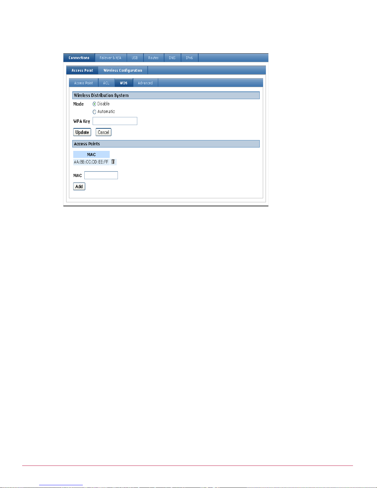
Network Setup menu options
Wireless
Figure 90 WDS
In the Wireless Distribution System pane, select an option for Mode. This is the mode that WDS is
3
operating in. Available options are:
• Disable — Disables WDS completely.
• Automatic — Enables bridging or repeating as appropriate. If the wireless interface is unconfigured,
then bridging is enabled (wireless clients cannot connect). Otherwise repeating is enabled.
4 Specify the WPA preshared key that is used for the WDS link in the WPA Key field. This key is only used
if the Access Point security method is configured for WPA-PSK or WPA-Enterprise. If the Security
Method is set to WEP, then the same WEP Key is used for both the wireless clients and the WDS link.
Note: You cannot enable both WDS and WEP with 802.1X.
• Can be exactly 64 hexadecimal characters (0-9, a-b, or A-B)
• Can be from 8 to 63 characters of any type
5 Click Update.
6 In the Access Points pane, specify the MAC address of an Access Point to create a WDS link to, and
then click Add. You can create up to 8 WDS links.
You can delete a WDS link using the delete icon in the WDS page. You can change the MAC address for a
WDS link using the edit icon in the Connections tab. The MAC address can be Ethernet MAC address of the
form AA:BB:CC:DD:EE:FF, where each component is a hexadecimal digit.
Configuring WDS bridging
Use this procedure to configure WDS bridging.
1 Configure the wireless settings on the Access Point tab.
2 Select the WDS tab.
3 Set Mode to Automatic.
4 Click Add and enter the MAC of the peer Access Point.
5 Click the Connections tab.
McAfee UTM Firewall 4.0.4 Administration Guide 91
Page 92

Network Setup menu options
Wireless
6 Create a new Bridge. Select both the LAN interface and the WDS interface to be on the bridge.
7 Leave the Wireless port unconfigured.
8 Configure the peer Access Point in a similar manner.
Configuring WDS repeating
Use this procedure to configure WDS repeating.
1 Configure the wireless settings on the Access Point tab.
2 Select the WDS tab.
3 Set Mode to Automatic.
4 Click Add and enter the MAC of the main Access Point.
5 Click the Connections tab.
6 Create a new Bridge. Select both the Wireless interface and the WDS interface to be on the bridge.
7 Configure the main Access Point in a similar manner; however, it will typically include the LAN interface
on the bridge.
Configuring automatic WDS bridging and repeating
Use this procedure to configure WDS bridging and repeating:.
1 Configure the wireless settings on the Access Point tab.
2 Select the WDS tab.
3 Set Mode to Automatic.
4 Click Add and enter the MAC of the main Access Point.
5 Click the Connections tab, create a new Bridge. Select the Wireless interface, the LAN interface, and
the WDS interface to all be on the bridge.
Configuring advanced wireless features
Use this procedure to configure advanced wireless settings. The default settings should be sufficient for
most configurations. Make sure the correct region is configured for your access point, since the region
setting restricts channels and frequencies in accordance with the local regulatory organization. Tweaking
these advanced wireless features can increase processing overhead, so balance performance requirements
with this in mind. Advanced wireless settings include packet fragmentation, RTS (Request to Send), and
beacon frames.
Normally, when a packet has an error, the entire packet must be retransmitted. If packet fragmentation is
enabled, the packet is split up into smaller fragments, and thus only the fragment that has an error needs
to be retransmitted, which increases performance. Fragmentation incurs an overhead per fragment, so
enabling it when it is not needed decreases performance.
RTS is used to negotiate when wireless clients can transmit. If you have two wireless clients out of range of
each other but both still within range of the access point, they may both attempt to transmit at the same
time, which causes a collision. Enabling RTS avoids these collisions, and thus increases performance. RTS
incurs an overhead for transmitting, so enabling it when it is not needed decreases performance. Since the
access point is in range of all wireless clients, you would not typically enable RTS for an access point.
Beacon frames are used to coordinate the wireless network. Sending beacon frames more often (that is,
using a lower beacon interval) increases responsiveness, but decreases performance due to higher
overheads. A DTIM (Delivery Traffic Indication Message) is periodically included in the beacon frame. A
DTIM indicates to clients in power-saving mode that there are packets for them to receive. Sending a DTIM
more frequently increases responsiveness for clients in power-saving mode, but uses more electrical power
since the clients must stay awake longer.
92 McAfee UTM Firewall 4.0.4 Administration Guide
Page 93

Network Setup menu options
Wireless
1 From the Network Setup menu, click Network Setup > Connections tab. The Connections tab opens.
On the Connections tab, click the edit icon alongside the Wireless interface.
2 Click Wireless Configuration tab > Advanced tab. The Advanced Configuration page for wireless
appears (Figure 91).
Figure 91 Wireless Advanced configuration
Select the region in which the access point is operating from the Region list. The region setting restricts
3
the allowable frequencies and channels. If your region is not listed, select a region that has similar
regulations.
4 Select a protocol from the Protocol list. Available options are:
• 802.11b only – Wireless clients can only connect using
802.11b (11 Mbit/s). Most wireless clients that support 802.11g also support 802.11b.
• 802.11g only – Wireless clients can only connect using
802.11g (54 Mbit/s). Wireless clients that only support 802.11b are unable to connect.
• 802.11b and 802.11g – [Recommended, default] Both 802.11b and 802.11g wireless clients can
connect.
Note: Be aware that all clients need to connect using the same protocol. As such, if 802.11b clients
connect, all wireless connections will be using the 802.11b protocol, even those clients that support
802.11g.
5 Enter the transmit power for the access point in the Transmit Power (%) field. Decreasing the power
reduces the range of the wireless network and reduces interference to other nearby access points. The
field attributes are as follows:
•Range: 1-100
• Default: 100%
6 Select a preamble length from the Preamble Type list. The preamble is part of the physical wireless
protocol. Available options are:
• Long (Default)
• Short – Short preambles can increase throughput; however, some wireless clients might not support
short preambles.
McAfee UTM Firewall 4.0.4 Administration Guide 93
Page 94

Network Setup menu options
Bridging
7 [Optional] To enable RTS, select the Enable RTS checkbox. Default: Disabled.
8 [Conditional; complete if RTS is enabled] Enter a minimum packet size in the RTS Threshold field.
Collisions are less likely for smaller packets, and so the overhead of using RTS for these might not be
worthwhile. The field attributes are as follows:
• Range 1-2346
• Default: 2346
9 [Optional] To enable, select the Enable Fragmentation checkbox. Default: Disabled.
10Enter a fragment size in the Fragmentation Length field. Smaller fragments decrease the amount
retransmitted when there is an error; however, it increases the total processing overhead for each packet.
• Range 256-2345
• Default: 2345
11Specify the interval between beacon frames in the Beacon Interval (ms) field.
• Range 20-999
•Default: 100
12Specify how often a DTIM interval is included in the beacon frame in the DTIM Interval (beacons) field.
Bridging
•Range 1-255
•Default: 1
13Click Update.
The appliance can be configured to bridge between network interfaces. When two or more network
interfaces are bridged, the appliance learns and keeps track of which hosts are reside on either side of the
bridge, and automatically directs network traffic appropriately.
One advantage of bridging network interfaces is that hosts on either side of the bridge can communicate
with hosts on the other side without having to specify a route to the other network via the appliance.
Another advantage is that network traffic not usually routed by an unbridged interface, such as broadcast
packets, multicast packets, and any non-IPv4 protocols such as IPv6, IPX, or Appletalk pass over the bridge
to their destination host.
Caution: You must trust all devices that are directly connected to bridged interfaces. Since the firewall does not
know which IP addresses for the bridged network belong on which interface, this means it is easy for a directly
connected device to spoof an IP address. You can manually add Packet Filter rules to prevent spoofing.
Furthermore, non-IP protocols are not restricted by the firewall. You should not bridge between interfaces
with different firewall classes if you are using non-IP protocols. Bridging only supports Ethernet and GRE
network interfaces. Since bridging can only be configured as a Direct Connection, you cannot bridge a
PPPoE connection. If you want to bridge a wireless interface to a LAN connection, see Bridging wireless and
LAN connections.
Adding a bridged interface
Use this procedure to add a bridged network interface. When network interfaces are bridged, they all share
a common configuration for the network connection. This means that a single IP address is used on all of
the network interfaces. Bridging network interfaces involves creating and then associating existing network
interfaces with a Bridge interface. Once this bridge interface has been added, it appears on the Network
Setup page under the Connections tab, along with the UTM Firewall appliance’s other network interfaces.
Prerequisites:
• If high availability is configured for a connection, it must be modified or disabled before bridging.
94 McAfee UTM Firewall 4.0.4 Administration Guide
Page 95

Network Setup menu options
Bridging
• A bridge cannot include multiple VLANS on the same switch.
• If a DHCP server is used for a connection, and the bridge you are adding uses a static IP, then the settings
are incompatible. DHCP must be disabled or deleted.
To add a bridge
1 From the Network Setup menu, click Network Setup and select the Connections tab.
2 From below the main Connections table, select Bridge from the list and click Add. The Bridge
Configuration tab appears (Figure 92).
Figure 92 Network Setup Edit Bridge Configuration page
3
If you want to transfer the IP address settings of an existing network connection to the bridge interface,
select it from the Existing Interface Configuration list. Otherwise, select None.
Note: Since the appliance automatically directs network traffic, hosts on either side do not need to specify this
IP address as a gateway to the networks connected to the bridge. It is not so important which IP address you
choose to assign to the bridge interface; it is primarily used by hosts on either side of the bridge only to
connect to the Management Console of the appliance. Specific routes are still required to reach networks that
are not being bridged.
4 Click Next. If you selected an existing interface, the Edit Bridge Configuration page appears. Skip to
Step 5 (page 96). If you selected None, the Direct Connection Settings page appears (Figure 93).
Figure 93 Direct Connection Settings page (bridging)
Complete the Direct Connection Settings fields.
a [Optional] Enter a connection name.
b Either indicate the DHCP is assigned by selecting the DHCP assigned checkbox, or enter an IP
address.
c [Conditional if not using DHCP] Enter the Subnet Mask.
d [Optional, can be left blank] Enter the IP address for the Gateway.
e [Optional, can be left blank] Enter the IP address for the DNS Server.
f Click Next. The Edit Bridge Configuration page appears. Continue with the next step.
McAfee UTM Firewall 4.0.4 Administration Guide 95
Page 96

Network Setup menu options
Bridging
5 The Edit Bridge Configuration tab appears (Figure 94).
Figure 94 Network Setup Edit Bridge Configuration page
6
For each network interface you want to bridge, select the Bridged checkbox. Selecting this checkbox for
an interface places the interface on the bridge.
Note: If a network interface is placed on the bridge, its current configuration is deleted.
7 Ensure its Firewall Class is set appropriately.
8 [Optional] If you have multiple bridges connected together on your network, select the Enable Spanning
Tree Protocol checkbox. This setting allows the bridges to exchange information, helping to eliminate
loops and find the optimal path for network traffic.
9 Enter the time in seconds between when the bridge interface comes online and when it begins forwarding
packets in the Forwarding Delay field. The delay usually only occurs when the appliance first boots, or
when the bridge configuration is modified. This delay allows the appliance’s bridge to detect which hosts
are connected to each of the bridge’s interfaces, rather than blindly sending network traffic out all network
interfaces.
Can be zero (0) or greater
10Click Next to review or change IP address information for the bridge interface, otherwise click Finish.
Example 1: Transferring existing settings while adding a new bridge
This example steps through the sequence when transferring the IP address settings of an existing network
connection to the bridge interface you are adding.
1 From the Network Setup menu, click Network Setup and select the Connections tab. The
Connections page appears.
2 From below the main Connections table, select Bridge from the list and click Add. The Bridge
Configuration tab appears.
3 Select the interface from the Existing Interface Configuration list. This example transfers the settings
from the Switch A LAN interface (Figure 95).
Figure 95 Example transfer configuration to bridge
96 McAfee UTM Firewall 4.0.4 Administration Guide
Page 97

Network Setup menu options
Bridging
4 Click Next. The Edit Bridge Configuration tab appears (Figure 96).
Figure 96 Network Setup Edit Bridge Configuration page
5
Select the checkbox for the other Interface you want to bridge.
6 Click Finish.
Example 2: Adding a bridge without transfer
This example steps through the sequence when simply adding a new bridge interface without transferring
settings from an existing configuration.
1 From the Network Setup menu, click Network Setup and select the Connections tab. The
Connections page appears.
2 From below the main Connections table, select Bridge from the list and click Add. The Bridge
Configuration tab appears.
3 From the Existing Interface Configuratio n list, select None.
4 Click Next. The Bridge Configuration tab containing the Direct Connection Settings page appears
(Figure 97).
Figure 97 Bridge Configuration Direct Connection Settings page
5
Enter test_bridge in the Connection Name field.
6 Enter 1.1.1.3 in the IP Address field.
7 Click Next. The Edit Bridge Configuration page appears (Figure 98).
McAfee UTM Firewall 4.0.4 Administration Guide 97
Page 98

Network Setup menu options
Bridging
Figure 98 Bridge Configuration Direct Connection Settings page
8
Select the Bridged checkboxes for Switch A and Port B.
9 Click Finish.
Deleting a bridge
Use this procedure to delete a bridge. Deleting a bridge transfers the IP configuration of the bridge to
another interface.
1 From the Network Setup menu, click Network Setup and select the Connections tab. The Connections
page opens.
2 Click the delete icon for the bridge you want to delete. The Bridge Deletion page appears (Figure 99).
Figure 99 Bridge Deletion page
3
Select the interface to which to transfer the bridge’s IP configuration, if available, or select None.
4 Click Finish.
Bridging across a VPN connection
Bridging across a VPN connection is useful for:
• Sending IPX/SPX over a VPN, something that is not supported by other VPN vendors.
• Serving DHCP addresses to remote sites to ensure that they are under better control (which can also be
achieved with a DHCP relay. See DHCP Relay page).
• Allowing users to make use of protocols that do not work well in a WAN environment (such as netbios).
98 McAfee UTM Firewall 4.0.4 Administration Guide
Page 99

VLAN
Network Setup menu options
VLAN
VLAN (Virtual Local Area Network) is a method of creating multiple virtual network interfaces using a single
physical network interface. Packets in a VLAN are simply Ethernet packets that have an extra four bytes
immediately after the Ethernet header. The format for these bytes is defined by the standard IEEE 802.1Q.
Essentially, they provide for a VLAN ID and a priority. The VLAN ID is used to distinguish each VLAN. A
packet containing a VLAN header is called a tagged packet.
Note: VLANs are not supported by the SG310.
When a packet is routed out the VLAN interface, the VLAN header is inserted and then the packet is sent
out on the underlying physical interface. When a packet is received on the physical interface, it is checked
for a VLAN header. If present, the router makes it appear as though the packet arrived on the
corresponding VLAN interface.
Caution: Since the addition and removal of the VLAN header are performed in software, any network device can
support VLANs. Further, this means that VLANs should not be used for security unless you trust all the de vices on
the network segment.
Once added, VLAN interfaces can be configured as if they were additional physical network interfaces. A
typical use of VLANs with the UTM Firewall appliance is to enforce access policies between ports on an
external switch that supports port-based VLANs. In this scenario, only the switch and other trusted devices
should be directly connected to the LAN port of the UTM Firewall appliance. The UTM Firewall appliance and
the switch are configured with a VLAN for each port or group of ports on the switch. The switch is
configured to map packets between its ports and the VLANs. The UTM Firewall appliance can then be
configured with firewall rules for the VLANs, and these rules are effectively applied to the corresponding
ports on the switch.
Additionally, Switch A on the SG560, SG560U, SG565, and SG580 supports port-based VLANs. One benefit
of this feature is that you can assign individual functions to each of the ports on the switch; for example,
you might decide to use port A2 to connect to a DMZ, and port A3 as a second Internet connection. For
details, see Port-Based VLANs.
Adding a VLAN
1 From the Network Setup menu, click Network Setup. The Connections page appears.
2 Select VLAN from the list and click Add. The VLAN Configuration tab appears (Figure 100).
Figure 100 Network Setup VLAN Configuration
3
From the Interface list, select the network interface on which to add the VLAN.
4 Enter a value for the VLAN ID in the VLAN ID field. The value can be a decimal number between 1 and
4094. If this VLAN interface is to participate on an existing VLAN, the VLAN ID number entered in this
field must match the ID of the existing VLAN. This ID must be unique amongst the VLANs on this Ethernet
interface.
McAfee UTM Firewall 4.0.4 Administration Guide 99
Page 100

Network Setup menu options
VLAN
5 Port / Mode: If this table is displayed, this interface has been enabled for port-based VLANS. For more
information, see Port-Based VLANs. Select the VLAN mode for the port. This option is only available when
port-based VLANs are enabled. The choices are:
• Disabled – Packets on this VLAN are not sent or received on this port. If a port is disabled for all
VLANs, then the port is set to untagged mode for the default VLAN of the switch.
• Tagged – Packets on this VLAN are sent and received on this port as tagged packets that contain a
VLAN header. This is identical to how the switch would handle the packet when port-based VLANs are
disabled. Devices connected to this port must support VLANs.
• Untagged – Packets on this VLAN are sent and received on this port as untagged packets without a
VLAN header. This means that the VLAN ID will only be used while routing the packet within this
appliance. Devices connected to this port will not see the VLAN ID on the packet, and do not need to
support VLANs. If a port is set to untagged, then that port must be set to disabled for all other VLANs.
A port can be set to tagged for multiple VLANs. It is also allowable for more than one port to be set to
untagged for a given VLAN.
6 Click Update. You have now added a tagged VLAN interface that you can configure as you would any
other network interface. Select the connection type from the Change Type list and configure a
connection for the VLAN interface.
Port-Based VLANs
A port-based VLAN configuration is required for certain UTM Firewall models to be configured for an
additional WAN, LAN, or DMZ. The SG560, SG560U, SG565, and SG580 models have a built in
VLAN-capable switch. This gives you the flexibility to either use it as a simple switch that allows access
between all ports (the default), or use port-based VLANs to control access between each individual port in
the switch. This port-based VLAN configuration makes it possible to: assign each of the four ports its own
subnet address; declare it to be a LAN, WAN, or DMZ independent of the other ports; or treat the switch
port as if it were a completely separate physical port.
Note: Port-based VLAN is applicable to models SG560, SG560U, SG565, and SG580 only.
The UTM Firewall appliance can also participate on an existing VLAN. When you add a VLAN interface to
connect to the existing VLAN, you can associate the VLAN with one or more UTM Firewall ports.
Tagged and untagged VLANs
When using port-based VLANs, it is important to understand the differences between tagged and untagged
VLANs. Tagged VLAN interfaces add a VLAN header (see VLAN) to outgoing network packets, and only
accept incoming network packets that contain an appropriate VLAN header. Untagged VLAN interfaces do
not add a VLAN header to outgoing network packets, and do not accept incoming packets containing a
VLAN header.
A port can be a member of either a single untagged VLAN, or one or more tagged VLANs. A port cannot be
a member of both tagged and untagged VLANs.
Once Switch A has port-based VLANs enabled, ports that have not been explicitly assigned to one or more
VLANs are assigned to the default VLAN, which is untagged.
Typically, a tagged VLAN interface is used when you want to join an existing VLAN on the network, and an
untagged VLAN interface is used when you are using the port-based VLAN feature to isolate the ports so
that you can configure each of them individually.
Rules and limitations of port-based VLANs
There are few rules and limitations to keep in mind when using port-based VLANs:
• Switch A can only have one default VLAN, and any ports that are not explicitly assigned to another VLAN
are automatically placed on the default VLAN. The default VLAN is untagged.
• You cannot add tagged VLANs to port A1; it is a member of the default VLAN only.
100 McAfee UTM Firewall 4.0.4 Administration Guide
 Loading...