

Page 1
NTBA Appliance T-200 and T-500 Quick Start Guide
McAfee Network Security Platform
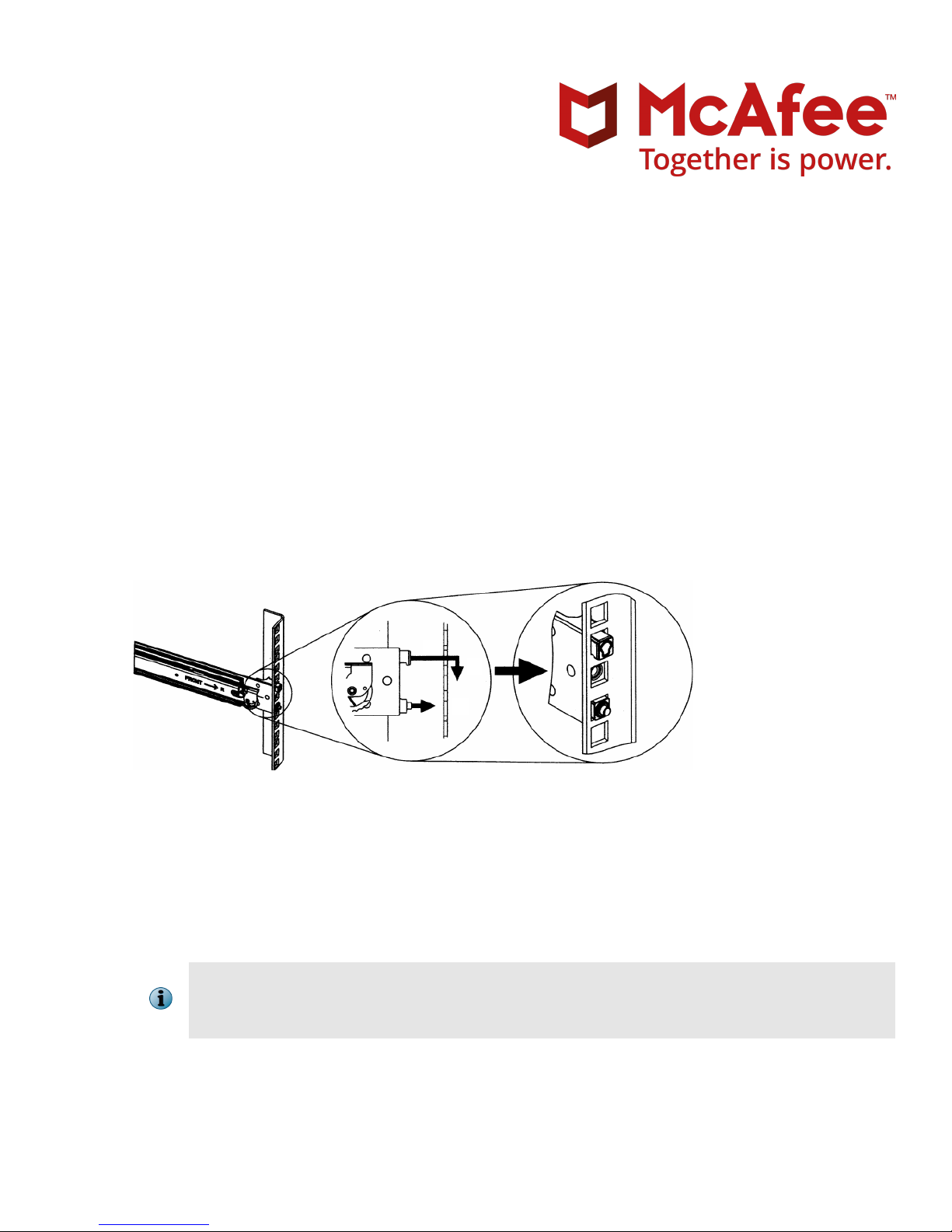
1 Install the mounting rails
Position the mounting rails correctly and install them at same levels.
At the front of the rack, position one of the mounting rails so that its mounting bracket aligns with the
a
required rack holes. Clip the rail into the rack.
Revision B
Figure 1 Slide rail installation
At the back of the rack, pull the back mounting-bracket (extending the mounting rail) so that it aligns with
b
the required rack holes.
Clip the rail to the rack and secure it.
c
Repeat these steps to secure the second mounting rail to the rack.
d
Make sure that the mounting rails are at the same level on each side of the rack.
e
Make sure that you follow the safety warnings. When identifying where you want the NTBA
Appliance to go in the rack, remember that you should always load the rack from the bottom
up. If you are installing multiple NTBA Appliances, start with the lowest available position rst.
1
Page 2
Install the NTBA Appliance in the mounting rails
With help from another person, lift the NTBA Appliance so that the side rails at the back of the NTBA
1
Appliance are aligned with the mounting rails in the rack, then push the NTBA Appliance into the
mounting rails until it stops.
Lifting the NTBA Appliance and attaching it to the rack is a two-person job.
Use a screwdriver to x a screw through the front and back rack holes to secure the system to the rack.
2
Attach the provided cable management arm if required.
3
Attach the lockable bezel to protect the front panel if required.
4
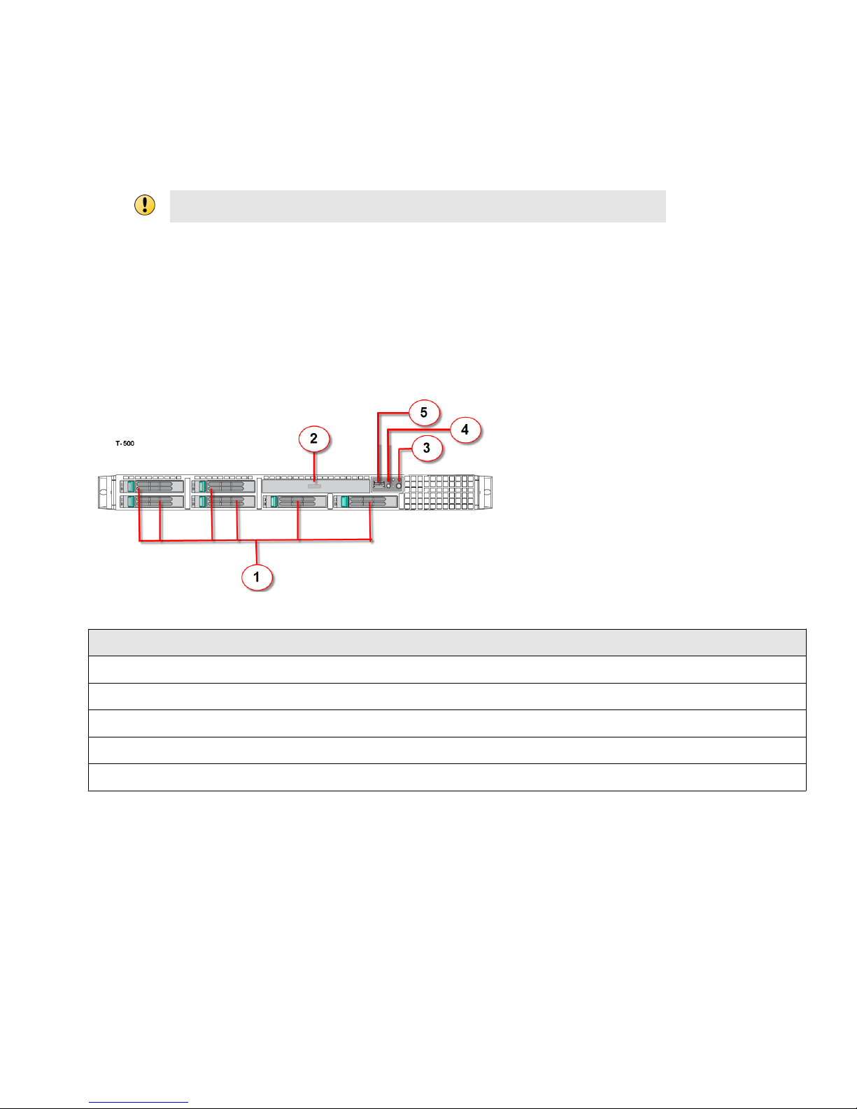
2 Front panel features and indicators T-500 and T-200
The front panel features and indicators of NTBA Appliance T-500 and T-200 are as follows:
Figure 2 Front panel — T-500 and T-200
Item Description
1 Hard drives
2 Optical drive
3 Power-on indicator (on the Mini Control Panel)
4 System identication indicator light (on the Mini Control Panel)
5 USB connector (on the Mini Control Panel)
2
Page 3
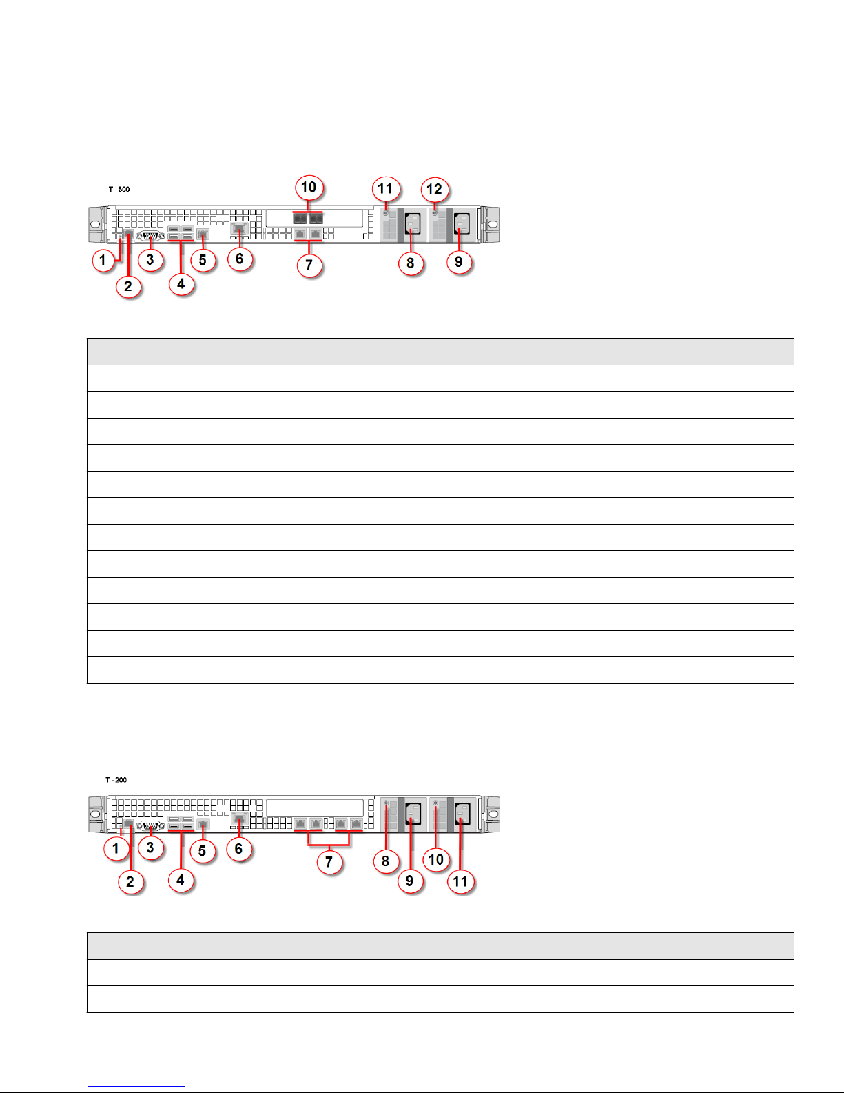
3 Back panel features and indicators T-500
The back panel features and indicators of NTBA Appliance T-500 are as follows:
Figure 3 Back panel — T-500
Item Description
1 System identication indicator light
2 Console port
3 Video connector
4 USB ports (4)
5 Management port
6 Remote management module NIC
7 Collection ports (2-copper)
8 Power supply 1
9 Power supply 2
10 Collection ports (2-ber)
11 Power supply 1 status indicator light
12 Power supply 2 status indicator light
4 Back panel features and indicators—T-200
The back panel features and indicators of NTBA Appliance T-200 are as follows:
Figure 4 T-200 back panel
Item Description
1 System identication indicator light
2 Console port
3
Page 4

Item Description
3 Video connector
4 USB ports (4)
5 Management port
6 Remote management module NIC
7 Collection ports (4-copper)
8 Power supply 1 status indicator light
9 Power supply 1
10 Power supply 2 status indicator light
11 Power supply 2
5 Hardware specications
Table 1 Hardware specications
Appliance model T-200 T-500
Form factor 1U 1U
Width 16.9" (430 mm) 16.9" (430 mm)
Depth 27.19" (690.6 mm) 27.19" (690.6 mm)
Height 1.69" (43 mm) 1.69" (43 mm)
Maximum weight 17.2 kg (38.1 lbs) 17.2 kg (38.1 lbs)
Redundant power supply 650W 650W
Quiescent power utilization 170W 225W
Estimated inlet power utilization (worst case scenario) 426W 544W
6 NTBA Appliance - technical specications
Table 2 NTBA Appliance technical specications
Parameter Limits
Dimensions
• Height - 43.2 mm 1.70 in • Depth without CMA - 665.5
• Width without rails - 430.0
mm 16.93 in
• Width with rails - 470.0 mm
18.50 in
mm 26.2 in
• Depth with CMA - 812.8 mm
32.00 in
Operating Temperature +10°C to +35°C with the maximum rate of change not to exceed 10°C per
Non- Operating Temperature -40°C to +70°C
4
hour
Page 5

Table 2 NTBA Appliance technical specications (continued)
Parameter Limits
Non- Operating Humidity 90%, non-condensing at 35°C
Acoustic noise Sound power: 7.0 BA in an idle state at typical oce ambient temperature.
(23 +/- 2°C)
Shock, operating Half sine, 2 g peak, 11 milliseconds
Shock, unpackaged Trapezoidal, 25 g, velocity change 136 inches/second (≥40 lbs to <80 lbs)
Shock, packaged Non-palletized free fall in height 24 inches (≥40 lbs to <80 lbs)
Vibration, unpackaged 5 Hz to 500 Hz, 2.20 g RMS random
ESD +/- 15 KV except I/O port +/- 8 KV per Intel® Environmental test specication
System Cooling Requirement
2250 BTU/hour
in BTU/Hr
7 Cabling the T-500 NTBA Appliance
The T-500 NTBA Appliance has four collection ports and one management port.
The collection ports connect to the network infrastructure that generates the NetFlow data from the routers
and McAfee® Network Security Sensor (Sensor)s.
The four collection ports can be used to distribute the NetFlow data from dierent routers and Sensors.
The management port connects to a network device that in turn connects to the Manager. The NTBA
Appliance is managed through the Manager.
Ports for cabling in the back panel
Figure 5 T-500 back panel
Item Description
1 Console port
2 Management port
3 Collection ports (2-copper)
4 Collection ports (2-ber)
5
Page 6

8 Cabling the T-200 NTBA Appliance
The T-200 NTBA Appliance has four collection ports and one management port.
The collection ports connect to the network infrastructure that generates the NetFlow data from routers and
McAfee® Network Security Sensor (Sensor)s.
The four collection ports can be used to distribute the NetFlow data from dierent routers and Sensors.
The management port connects to a network device that in turn connects to the Manager. The NTBA
Appliance is managed through the Manager.
Ports for cabling in the back panel
Figure 6 T-200 back panel ports
Item Description
1 Console port
2 Management port
3 Collection ports (2-copper)
4 Collection ports (2-copper)
9 Connect the console ports
Plug a console cable (RJ45 to DB9 serial) to the console port at the back panel of the NTBA Appliance.
a
Connect the other end of the cable directly to the serial port of the PC or Terminal Server you will be
b
using to congure the NTBA Appliance (for example, a PC running correctly congured Windows
HyperTerminal software.)
6
Page 7

You must connect directly to the console for initial conguration. You can't congure the NTBA Appliance
remotely.
The required settings for HyperTerminal are:
Name Setting
Baud rate 115200
Number of Bits 8
Parity None
Stop Bits 1
Control Flow None
The procedure for cabling the console port of NTBA Appliance T-1200 and T-600 is similar.
10 Connect the power cables
Connect one end of the power cable to the NTBA Appliance. Plug the other end of the power cable into a
grounded electrical outlet or a separate power source such as an uninterrupted power supply (UPS) or a
power distribution unit (PDU).
When you connect power to the appliance, the appliance will immediately turn on and boot up.
11 Install the Manager software
Prepare the system according to the requirements outlined in the McAfee® Network Security Platform
a
Installation Guide and McAfee Network Security Platform Release Notes.
Close all open applications.
b
Insert the Manager CD into the appropriate drive of the Windows server that you want to use as your
c
Manager server. Follow the instructions in the Installation Wizard as it guides you through the entire
process.
You must have administrator rights on the target Windows server to install the Manager
software.
A MySQL database is included with the Manager and is installed (embedded) automatically on
your target Windows server during this process.
7
Page 8

12 Add the NTBA Appliance to the Manager
Adding an NTBA Appliance to the Manager enables the Manager to accept communication from a physically
installed and network-connected Appliance. After communication has been established, the Manager allows
editing of the Appliance conguration. The alert data is available in the Attack Log and Report queries.
You can add a device by selecting Devices | <Admin Domain Name> | Global | Add and Remove Devices but it
is recommended to use the Add Device Wizard to add all devices (except Virtual HIP Sensors) and to
establish the trust between the Manager and the device.
a The Add Device Wizard window is displayed after the Manager Initialization Wizard is completed.
McAfee recommend to rst add an Appliance to the Manager.
Select Devices | <Admin Domain Name> | Global | Add Device Wizard.
The Preparation page is displayed.
b Click Next.
The Add New Device page is displayed.
Enter the device name.
c
The name must begin with a letter and can contain alphanumeric characters, hyphens, underscores and
periods. The length of the name is not
congurable.
d Select the Device Type as NTBA Appliance.
e Enter the Shared Secret (repeat at Confirm Shared Secret).
The device name and shared secret are case-sensitive. The Device Name and Shared Secret must also be
entered on the device command line interface (CLI) during physical installation and initialization. If not,
the Appliance will not be able to register itself with the Manager.
The shared secret must be a minimum of 8 characters in length: the length of the shared secret is not
congurable. The shared secret cannot start with an exclamation mark or have any spaces. The characters
that can be used while creating a shared secret are as follows:
• 26 alpha: upper and lower case (a,b,c,...z and A, B, C,...Z)
• 10 digits: 0 1 2 3 4 5 6 7 8 9
• 32 symbols: ~ ` ! @ # $ % ^ & * ( ) _ + - = [ ] { } \ | ; : " ' , . <? /
f For a NTBA Appliance, the Updating mode is set to Online.
g [Optional] Enter the Contact Information and Location.
h Click Next.
The Trust Establishment page is displayed.
8
Page 9

i Follow the instructions on the page to complete the command line interface (CLI) setup and click Check
Trust.
Using the command line interface (CLI), enter the necessary information for the Appliance
and communication as described in the McAfee Network Security Platform Installation Guide.
If you set up the NTBA Appliance rst, after the Manager addition, you need to return to the
Appliance to reset the shared secret key and begin Appliance-to-Manager communication.
j Click Next.
The Next button is enabled once the trust between the Appliance and the Manager is
established.
The Port Settings page is displayed. By default, the collection ports are disabled.
k Enable the ports and modify settings. Click Save and then Next.
The General Settings page is displayed.
Congure NTBA Appliance settings for collection ports. Click Next.
l
The DNS Settings page is displayed.
m By default global settings are inherited. If you wish, modify the DNS server details. Click Next.
The Exporters page is displayed.
identication
n Add a router exporter that will forward records to the NBA Sensor for processing and click Next. To add a
IPS exporter, go to IPS devices.
The Inside Zones page is displayed.
o Add a new inside zone or edit the default inside zones. Click Next.
The Outside Zones page is displayed.
p Add a new outside zone or edit the default outside zone. Click Next.
The Update Configuration page is displayed.
q Click Update to deploy
conguration on the device. This might take some time.
The Update Status bar displays 100% complete.
r Click Finish.
On the Devices tab, under the Device drop-down list, the NTBA Appliance is added. From Global | Add and
Remove Devices option, you can also view the added Appliance.
13 Set up NTBA Appliance
Plug a console cable (RJ45 to DB9 serial) to the console port at the back panel of the NTBA Appliance.
a
Connect the other end of the cable directly to the serial port of the PC or Terminal Server you are using to
b
congure the NTBA Appliance. (For example, a PC running correctly congured Windows HyperTerminal
software.)
9
Page 10

The required settings for HyperTerminal are:
Name Setting
Baud rate 115200
Number of Bits 8
Parity None
Stop Bits 1
Control Flow None
Run the HyperTerminal.
c
At the logon prompt, log on to the NTBA Appliance using the default user name admin and password
d
admin123.
At the Press Y to start the setup now or N to do it later prompt, enter Y. Set and conrm
e
a setup password. Wait for some time to congure the NTBA Appliance.
At the Please enter the sensor name prompt, enter the name of the NTBA Appliance.
f
The values between <> characters are to be entered by the user, excluding the <> characters.
Example: ntba_appliance_1
The NTBA Appliance name is a case-sensitive alphanumeric character string up to 25 characters. The
string must begin with a letter and can include hyphens. underscores, periods but not spaces. The NTBA
Appliance name typed here should be identical to the one entered against Device Name in the Add New
Device page of the Manager.
g At the Please enter the sensor IP(A.B.C.D) prompt, type the management port IP address of the
NTBA Appliance.
Specify a 32-bit address written as four eight-bit numbers separated by periods as in <A.B.C.D>, where A,
B, C, or D is an eight-bit number between 0-255.
Example: 10.213.173.237
Setting the IP address for the rst time during the initial conguration of the NTBA Appliance
does not require an NTBA Appliance reboot. Subsequent changes to the IP address however,
require reboot for the change to take eect.
At the Please enter the sensor subnet mask(A.B.C.D) prompt, type the management port
h
subnet mask of the Appliance. <A.B.C.D> represents the subnet mask.
Example: 255.255.255.0
At the Please enter the manager primary IPv4 address(A.B.C.D) prompt, type the IPv4
i
address of the Manager server.
Example: 192.34.3.2
(Optional) At the Press Y to configure manager secondary IP address prompt, type Y if you
j
wish to set a Manager secondary IP address. By default, this is set to N.
10
Page 11

At the Please enter the sensor default gateway(A.B.C.D) prompt, type the IP address. Use
k
the same convention as for the Sensor IP address.
Note that you should be able to ping the gateway. The gateway should be reachable.
Example: 192.34.2.8
Make sure you have set a shared secret key on the Manager for this Sensor.
l
At the Please enter shared secret key prompt, type the shared secret key value. This value is used
m
to establish a trust relationship between the NTBA Appliance and the Manager.
n Type the same shared secret key value that you typed in the Add New Device page of the Manager.
The NTBA Appliance prompts you to verify the value. Make sure that the conguration settings to this
point have successfully established the NTBA Appliance on the network.
o Type the value again and press ENTER.
You can change the NTBA Appliance password by using the passwd command.
A password must be between 8 and 25 characters, is case-sensitive, and can consist of any alphanumeric
character or symbol.
McAfee strongly recommends that you choose a password with a combination of characters
that is easy for you to remember but dicult for someone else to guess.
14 Verify successful NTBA Appliance conguration
You can check whether the NTBA Appliance is congured and is available by executing the following actions:
Verication process
You can check the NTBA Appliance conguration as follows:
• At the NTBA Appliance console type status.
The status information of the NTBA Appliance is displayed. This includes information on whether the
NTBA Appliance is initialized and its health status.
• At the NTBA Appliance console type show.
The system information is displayed. This includes information on system uptime and the status of the
Management port link.
To exit the session, type exit.
• To view or congure the settings of the collection ports for the NTBA appliance, you access the
conguration page in Devices | <Admin Domain Name> | Devices | <Device Name> | Setup | Physical Ports.
Download the latest NTBA Appliance software
a Select Manager | <Admin Domain Name> | Updating | Download Device Software.
The Download Device Software page is displayed.
b Select the latest software listed under Software Available for Download and click Download.
The Download Status window is displayed.
11
Page 12

c Click Close Window once the download is complete.
The downloaded software is listed under Software on the Manager in the Download Device Software page as also
in the Deploy Device Software page (Devices | <Admin Domain Name> | Devices | <NTBA Appliance> | Maintenance |
Deploy Device Software).
Upgrade NTBA Appliance software
You need to upgrade to the latest available version from the Manager.
a Select Devices | <Admin Domain Name> | Devices | <NTBA Appliance> | Maintenance | Deploy Device Software.
The Deploy Device Software page is displayed.
b Select the latest software listed under Software Ready for Installation and click Upgrade.
The Download Status page is displayed.
c Click Close Window once the download is complete.
Copyright © 2017 McAfee, LLC
McAfee and the McAfee logo are trademarks or registered trademarks of McAfee, LLC or its subsidiaries in the US and other countries. Other
marks and brands may be claimed as the property of others.
12 700-3622B00
 Loading...