

Page 1
NS9x00 Quick Start Guide
McAfee® Network Security Platform
This quick start guide explains how to quickly set up and activate your McAfee® Network Security Platform
NS-series Sensor in in-line mode.
All product documentation referenced in this quick start guide is found on the McAfee Service Portal.
The NS9100/NS9200 Sensor model
Revision E
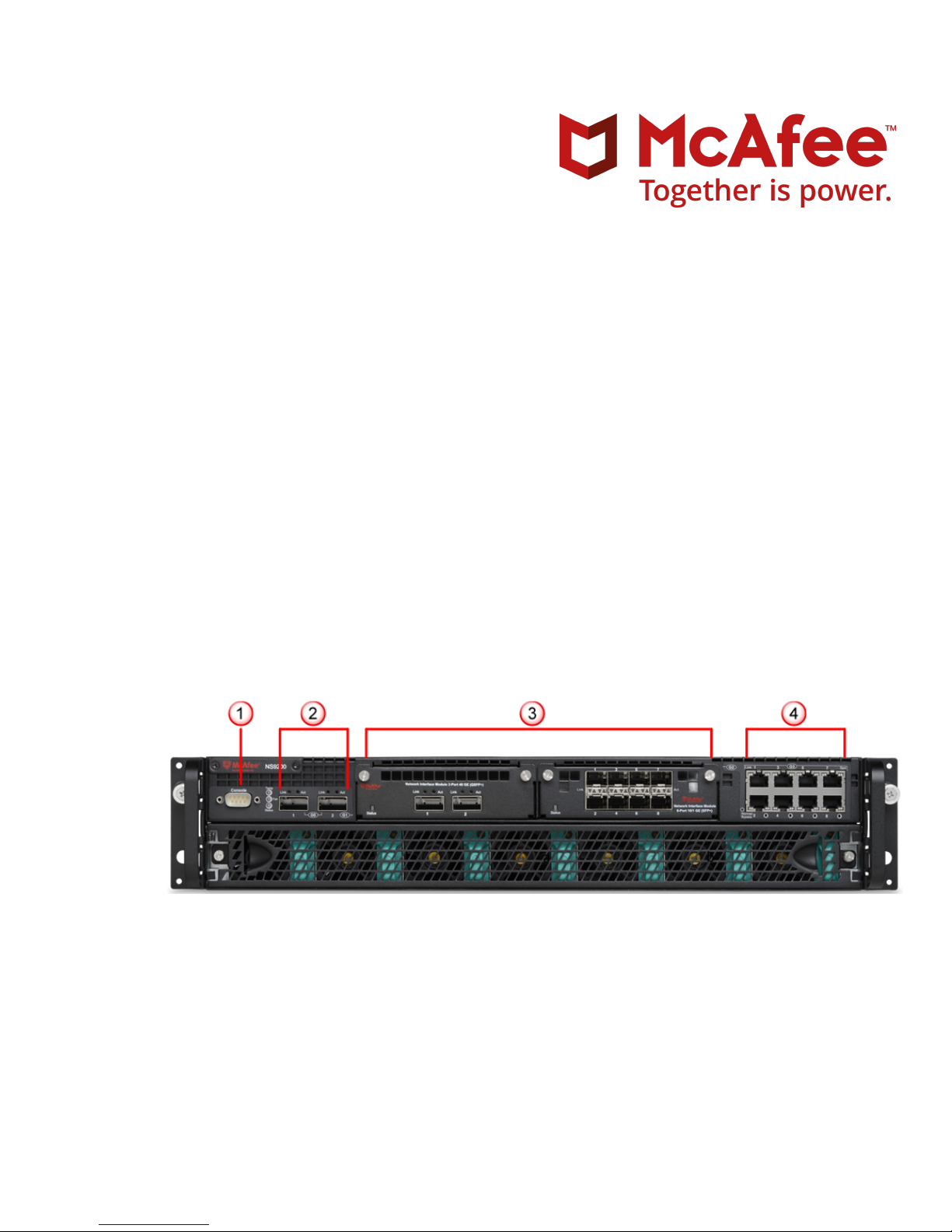
Figure 1 Sensor front panel
1
Console port (1)
2
QSFP+ 40 Gigabit Ethernet ports (2)
3
Two slots for I/O modules (Any combination of the interface modules can be used)
• QSFP+ 40 Gigabit Ethernet ports (4)
• QSFP+ 40 Gigabit Ethernet ports (2)
1
Page 2
• SFP/SFP+ 1/10 Gigabit Ethernet Monitoring ports (8)
• RJ-45 10/100/1000 Mbps Ethernet Monitoring ports (6)
4
RJ-45 10/100/1000 Mbps Ethernet Monitoring ports (8)
The supported transceiver modules are QSFP+, SFP+ (M2M and SM), SFP Fiber (MM and SM) and SFP Copper.
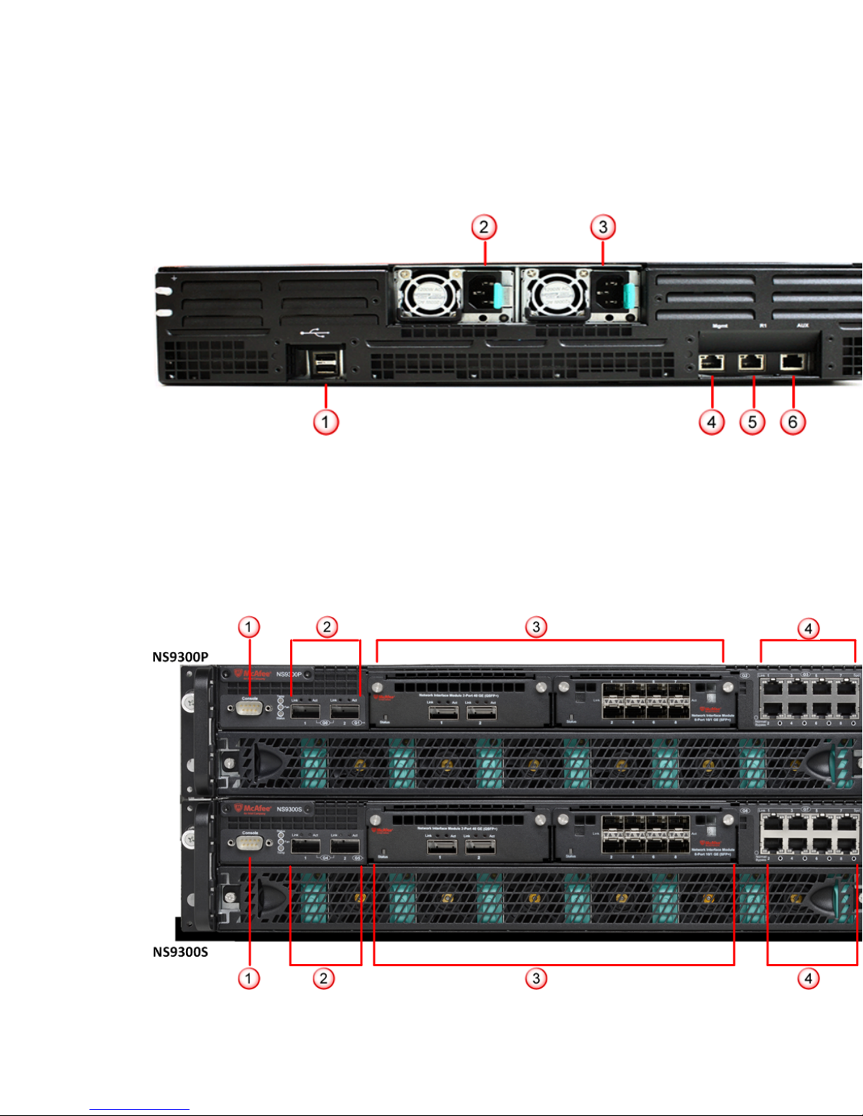
Figure 2 Sensor rear panel
1
USB ports (2)
4
RJ-45 100/1000/10000 Management port
(Mgmt) (1)
2
Power supply A (Pwr A)
3
Power supply B (Pwr B) (optional on NS9100)
The NS9300 Sensor model
5
RJ-45 100/1000/10000 Response port (R1) (1)
6
RJ-45 Auxiliary port (Aux) (1)
Figure 3 Sensor front panel
2
Page 3

The NS9300 Sensor consists of a Primary Sensor, NS9300P, and a Secondary Sensor, NS9300S.
1
Console ports on the NS9300P and NS9300S Sensors (2)
2
QSFP+ 40 Gigabit Ethernet Interconnect ports (4). G0/1 and G0/2 on NS9300P Sensor and G4/1 and G4/2 on
NS9300S Sensor.
3
Four slots for I/O modules (Any combination of the interface modules can be used)
• QSFP+ 40 Gigabit Ethernet ports (4)
• QSFP+ 40 Gigabit Ethernet ports (2)
• SFP/SFP+ 1/10 Gigabit Ethernet Monitoring ports (8)
• RJ-45 10/100/1000 Mbps Ethernet Monitoring ports (6)
4
RJ-45 10/100/1000 Mbps Ethernet Monitoring ports (16)
The supported transceiver modules are QSFP+, SFP+ (MM and SM), SFP Fiber (MM and SM) and SFP Copper.
Figure 4 Sensor rear panel
1
USB ports (4)
2
Power supply A (Pwr A)
3
Power supply B (Pwr B)
4
RJ‑45 100/1000/10000 Management port (Mgmt) (2). Mgmt on NS9300S Sensor is used as an interconnect
port.
5
RJ‑45 100/1000/10000 Response port (R1) (2). R1 on NS9300P Sensor is used as an interconnect port.
6
RJ‑45 Auxiliary ports (Aux) (2)
3
Page 4
Verify the contents in the box
The following accessories are shipped in the NS-series Sensor crate:
• Sensor
• Power supply
• Power cords. McAfee provides a standard and international power cables.
• Set of rack mounting rails
• Printed Quick Start Guide
Verify the hardware and software requirements
The following hardware requirements are to be met. For more information, see the Installation Guide.
The following are the system requirements for a Manager server.
Minimum required Recommended
OS
Any of the following:
• Windows Server 2008 R2 Standard or Enterprise Edition,
English OS, SP1 (64 bit) (Full Installation)
Same as the minimum
required.
• Windows Server 2008 R2 Standard or Enterprise Edition,
Japanese OS, SP1 (64 bit) (Full Installation)
Only X64 architecture is supported.
Memory 4GB 8GB
CPU Server model processor such as Intel Xeon Same
Disk space 100GB 300GB or more
Network 100Mbps card 100/1000/10000 Mbps card
Monitor 32-bit color, 1024 x 768 display setting 1280 x 1024
The following are the system requirements for client systems connecting to the Manager application.
Minimum Recommended
OS Windows 7
RAM 2 GB 4 GB
CPU 1.5 GHz processor 1.5 GHz or faster
Browser
OS Windows XP SP3.
RAM 1 GB 2 GB
Browser
• Internet Explorer 8.0 or 9.0.
• Mozilla Firefox 4.0 and above.
Minimum Recommended
• Internet Explorer 7.0 or 8.0.
Internet Explorer 9.0 .
Internet Explorer 8.0
• Mozilla Firefox 4.0 and above.
4
Page 5
The following software are to be installed.
• Sensor image
• Manager image
• Signature set
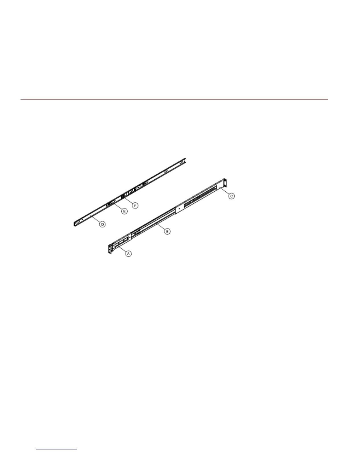
Install the slide rails
Follow this procedure to assemble the slide rails and position the Sensor on it.
Task
Rack installation - Remove inner member from slides
1
1
front bracket
2
outer member
3
rear bracket
Pull the release button to remove inner member from slides.
4
inner member
5
safety locking pin
6
release button
5
Page 6
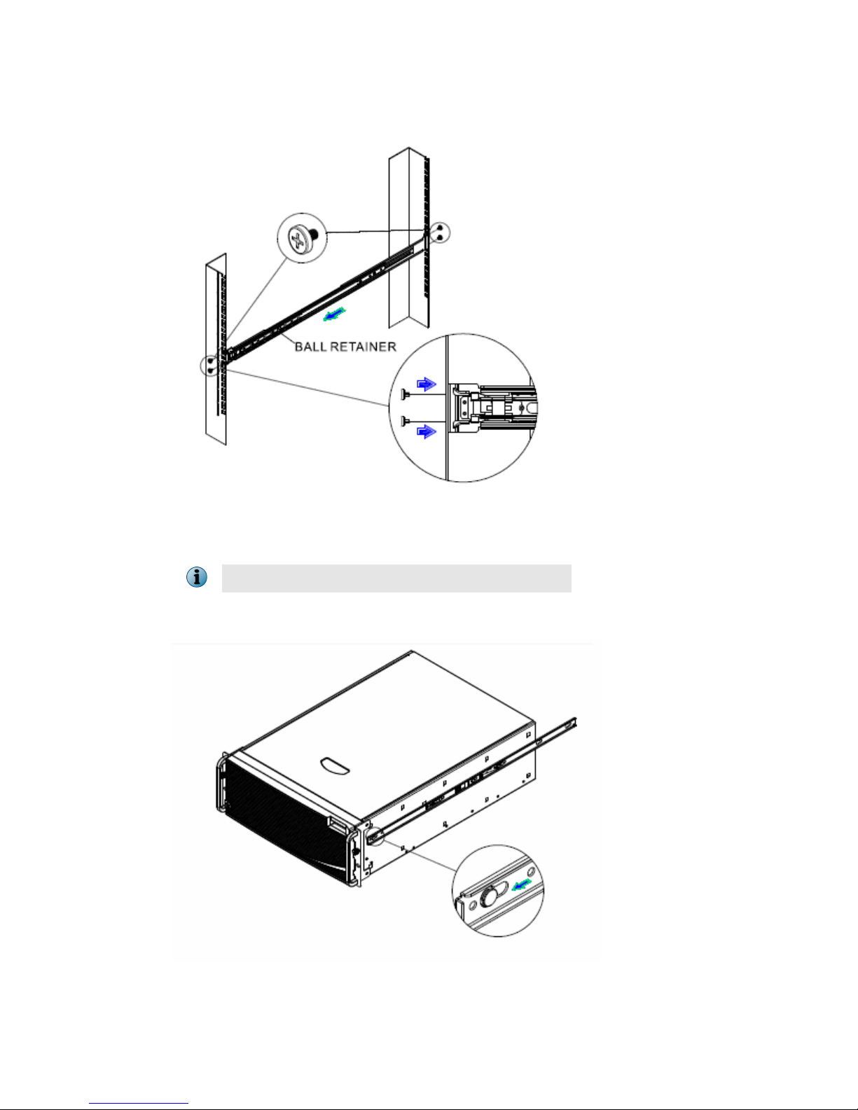
Rack installation - Install slides to rack
2
Align brackets to desired vertical position on the rack and insert the fasteners. Move the ball retainer to the
front of slides.
Do not handle the NS-series appliance by the mounting brackets
Chassis installation - Install inner member to chassis
3
Align inner member key holes to standos on chassis, move inner member following the direction the
picture.
6
Page 7

Chassis installation - Install chassis to xed slides
4
Pull the release button in the inner member to release the lock and allow the chassis to close.
Chassis removal - Extend slides
5
Fully extend the slides until it is in the locked position, pull the release button to release lock and disconnect
inner member from slides.
7
Page 8

Chassis removal - Remove inner member from chassis
6
Press safety locking pin to release inner member from chassis.
While installing NS9300, this procedure is to be followed for both the primary and the secondary Sensors.
Install the interface modules
You can purchase the following interface modules and insert them into the relevant slots on your NS-series
Sensor.
• 2-port QSFP+ 40 Gigabit interface module
• 4-port QSFP+ 40 Gigabit interface module
• 4-port SFP/SFP+ 10/1 Gigabit 8.5 µm (SM) interface module with internal fail-open
• 4-port SFP/SFP+ 10/1 Gigabit 50/62.5 µm (MM) interface module with internal fail-open
• 8-port SFP/SFP+ 1/10 Gigabit interface module
• 6-port RJ-45 10/100/1000 Mbps Ethernet interface module
8
Page 9

Task
Remove the module from its protective packaging.
1
Grip the sides of the module with your thumb and fore-nger and insert the module into the slot.
2
Drive in the screws xed on the sides of the module to attach it to the Sensor.
3
Cable the Management and Console ports
Task
1
Plug a Category 5e Ethernet cable in the Management port (labeled Mgmt):
on the rear panel of the NS9100 and NS9200 Sensors.
a
on the rear panel of the NS9300P Sensor.
b
Plug the other end of the cable into the network device connected to your Manager server.
2
3
9
Page 10

Plug the DB9 Console cable(s) into the Console port (labeled Console):
on the front panel of the NS9100 and NS9200 Sensors.
a
on the front panel of the NS9300P and NS9300S Sensors.
b
Connect the other end of the Console port cable directly to a COM port of the PC or terminal server you will
4
be using to congure the Sensor (for example, a PC running correctly congured Windows Hyperterminal
software). You must connect directly to the console for initial conguration; you cannot congure the Sensor
remotely.
Terminal servers are provided for console access.
The required settings for Hyperterminal are:
• Baud rate: 115200 • Stop Bits: 1
• Number of Bits: 8 • Control Flow: None
• Parity: None
Plug one end of the power cable into the power inlet and plug the other end into a power source. The
5
Sensor ships with standard US power and international cables.
The NS-series Sensor does not have a power switch; you need to only plug the power cable into a power
source.
Cable the Monitoring ports
This procedure describes how to cable a Sensor to run in In-line mode.
Task
1
Plug the cable appropriate for use with your transceiver module into one of the Monitoring ports labeled x
(for example, 1).
Plug the cable appropriate for use with your transceiver module into one of the Monitoring ports labeled y
2
(for example, 2).
Connect the other end of each cable to the network devices that you want to monitor. (For example, if you
3
plan to monitor trac between a switch and a router, connect the cable connected to 1 to the router and
the one connected to 2 to the switch.)
On the NS9300P Sensor, do not use ports G0/1 and G0/2 and on the NS9300S Sensor, do not use ports G4/1
and G4/2. These ports are reserved for interconnection between the NS9300P and NS9300S Sensors.
10
Page 11

Cable the Interconnect ports
This procedure describes how to connect the NS9300P Sensor to the NS9300S Sensor.
Task
Plug the supplied 40G Direct Attach cable into port G0/1 of the NS9300P Sensor and connect the other end
1
of the cable into port G4/1 of the NS9300S Sensor.
Plug the supplied 40G Direct Attach cable into port G0/2 of the NS9300P Sensor and connect the other end
2
of the cable into port G4/2 of the NS9300S Sensor.
Plug the supplied cable into the Response port (R1) of NS9300P Sensor and connect the other end of the
3
cable into the Management port (Mgmt) port of the NS9300S Sensor.
11
Page 12

Install the Manager Software
For detailed instructions, refer to McAfee Network Security Platform Installation Guide.
You must have administrator privileges on the target Windows server to install the Manager software.
A MySQL database is included with the Manager and is installed (embedded) automatically on your target
Windows server during this process.
Following steps briey explain the Manager installation:
Task
Prepare the system according to the requirements outlined in McAfee Network Security Platform Installation
1
Guide and the McAfee Network Security Platform Release Notes.
Close all open applications.
2
Go to McAfee Update Server (https://menshen.intruvert.com/) and log on, using the grant number and
3
password.
4 Go to Manager Software Updates folder and select the latest Manager software version available.
Download the zip le to the target Windows server and extract the setup le.
5
Double-click Manager_<version>_setup.exe and follow the on screen prompts.
6
Start the Manager
Click Start | Programs | McAfee | Network Security Manager | Network Security Manager.
Add the Sensor to the Manager
The Manager displays the Logon page.
Task
Log on to the Manager using the default username (admin) and password (admin123).
1
2 Click Configure.
12
Page 13

3 To add a Sensor in the Manager, click Device List | Devices, and then click New.
You do not require a license le to enable IPS on NS-series Sensors.
The Add New Device page is displayed.
Enter the following mandatory information in the appropriate elds.
4
• Device Name
The Sensor name must begin with a letter. The maximum length of the name is 25 characters.
• Device Type
Species the type of device to be added. Select IPS or NAC Sensor.
• Shared Secret
13
Page 14

The shared secret must be a minimum of 8 characters and maximum of 25 characters in length. The key
cannot start with an exclamation mark nor can have any spaces. The parameters that you can use to
dene the key are:
• 26 alphabets: upper and lower case (a,b,c,...z and A, B, C,...Z)
• 10 digits: 0 1 2 3 4 5 6 7 8 9
• 32 symbols: ~ ` ! @ # $ % ^ & * ( ) _ + ‑ = [ ] { } \ | ; : " ' , . <? /
The Sensor name and shared secret key that you enter in the Manager must be identical to
the shared secret that you will later enter during physical installation/initialization of the
Sensor (using CLI) in Step 10 - Congure Sensor information. If not, the Sensor will not be able
to register itself with the Manager.
• Updating Mode
Select Online or Offline.
Selecting Offline enables Oine Sensor update. Online is the default mode.
5 Click Save
Congure Sensor information
Congure the Sensor with the network information, a name, and the shared secret key that the Sensor uses to
establish secure communication with the Manager. Use the name and key values you set in Step 9 - Add the
Sensor to the Manager.
The rst time you congure a Sensor, you must have physical access to the Sensor.
At any time during conguration, you can type a question mark (?) to get help on the Sensor CLI commands. For
a list of all commands, type commands.
Task
Log on to the Sensor using the terminal connected to the Console port.
1
At the prompt, log on using the default Sensor username (admin) and password (admin123).
2
14
Page 15

Optional, but recommended. Change the Sensor password. At the prompt, type: passwd.The Sensor prompts
3
you to enter the new password and prompts you for the old password.
A password must contain between 8 to 25 characters, is case-sensitive, and can consist of any alphanumeric
character or symbol.
Set the name of the Sensor:
4
You can enter the setup command at the prompt and this will automatically prompt you to provide the
information shown in items d through g and item j. Or, you use the set command instead. If you use the set
command, you must manually enter the complete command syntax as shown in items d through g and item j.
At the prompt, type: set sensor name <word>.
Example: set sensor name HR_sensor1
The Sensor name is a case-sensitive character string up to 25 characters. The string can include hyphens,
underscores, and periods, and must begin with a letter.
If the Sensor is not on the same network as the Manager, set the address of the default gateway. At the
5
prompt, type: set sensor gateway <A.B.C.D>
Example: set sensor gateway 192.168.3.68
Set the IP address of the Manager server. At the prompt, type: set manager ip <A.B.C.D>.
6
Example: set manager ip 192.168.2.8
Set the IP address and subnet mask of the Sensor. At the prompt, type: set sensor ip <A.B.C.D>
7
<E.F.G.H>.
Example: set sensor ip 192.168.2.12 255.255.255.0
Specify an IP address using four octets separated by periods: X.X.X.X, where X is a number between 0 and
255, followed by a subnet mask in the same format.
If prompted, reboot the Sensor. Type: reboot
8
The Sensor can take up to ve minutes to complete its reboot.
Ping the Manager from the Sensor to determine if your conguration settings to this point have successfully
9
established the Sensor on the network. At the prompt, type:
ping <manager IP address>.
If the ping is successful, continue with the following steps. If not, type show to verify your conguration
settings and check that the information is correct.
Set the shared secret key value for the Sensor. At the prompt, type:
10
set sensor sharedsecretkey
The Sensor then prompts you to enter and, subsequently, conrm the shared secret key value.
This value is used to establish a trust relationship between the Sensor and the Manager. The secret key value
can be between 8 and 25 characters of any ASCII text. The shared key value is case-sensitive. Make sure the
value matches the shared secret key value you provided in the Manager interface in Step 9 - Add the Sensor to
the Manager.
To verify the
11
To exit the session, type exit.
12
conguration information, type show. Check that all information is correct.
15
Page 16

Verify successful installation
Task
In the Sensor CLI, type: status.
1
The status report appears.
The Sensor parameter System Initialized should be yes, and for Manager communication Trust
Established should be yes.
2 Return to the Manager. In the Manager Home page, view the Manager status in the System Health section.
The Manager status should be up and Sensor status should be active.
3 From the Manager Home page, click Configure to open the Configuration page.
16
Page 17

4 Select your added Sensor: Device List | <Device_Name>. The ports for this Sensor appear under the
<Device_Name> node.
<Device_Name> indicates the name of the Sensor you added.
5 A policy named Default Inline IPS is active upon Sensor addition. To view this policy, select IPS Settings | Policies
| IPS Policy Editor. Select Default Inline IPS from the list and click View / Edit.
The Default Inline IPS policy contains attacks already congured with a "blocking" Sensor response action; if
any attack in the policy is triggered, the Sensor automatically blocks the attack. To tune this or any other
McAfee-provided policies, you can clone the policy and then customize it as described in the McAfee Network
Security Platform IPS Administration Guide.
6 Click Device List | <Device_Name> | Port Settings.
To view port settings, select the port on the Sensor that you cabled. Ensure that your port settings match the
7
cabling, for example, if port 1 is cabled for the in-line mode then the Operating Mode in the port setting should
be in-line mode.
For more information on port settings, see Conguration Sensor monitoring and response ports, McAfee
Network Security Platform Device Administration Guide.
You're up and running!
Your Sensor is actively monitoring connected segments and communicating with the Manager for
administration and management operations.
17
Page 18

Task
For detailed usage instructions, see McAfee Network Security Platform Device Administration Guide, or click the
1
Detailed Help buttons in the upper-right corner of each window in the Manager.
2 Launch the Threat Analyzer from the Home page to view alert statistics as attacks are detected. A summary of
alerts is displayed in the Unacknowledged Alert Summary area of the Manager Home page.
Having problems? Check McAfee Network Security Platform Troubleshooting Guide for troubleshooting
3
information.
Note that most deployment problems stem from
4
conguration mismatches between the Sensor and the
network devices to which it is connected. Check your duplex and auto-negotiation settings on both devices
to ensure they are synchronized.
If you need to contact Technical Support, go to https://mysupport.mcafee.com.
Copyright © 2017 McAfee, LLC
McAfee and the McAfee logo are trademarks or registered trademarks of McAfee, LLC or its subsidiaries in the US and other countries. Other
marks and brands may be claimed as the property of others.
18
700-4096E00
 Loading...