

Page 1

NS5x00 Quick Start Guide
McAfee Network Security Platform
Overview
This quick start guide explains how to quickly set up and activate your McAfee® Network Security Platform
NS5100 and NS5200 Sensors in inline mode. These models have a throughput of 600 Mbps, and 1 Gbps
respectively.
All product documentation referenced in this quick start guide is found on the McAfee Service Portal.
The NS5100/NS5200 Sensor model
Revision C
Figure 1 Sensor front panel
1
Console port (1)
2
RJ-11 port (1) for fail-open control of two built-in SFP+ ports in slot G0. The RJ-11 ports support 1 Gbps (SFP)
ber and 10 Gbps (SFP+) (SR and LR). You can convert these ports to copper ports by using the copper SFP
transceivers.
3
SFP/SFP+ 1/10 ber Gigabit or SFP 1 Gbps copper Ethernet ports (2)
4
RJ-11 port (6) for external passive fail-open control of twelve SFP ports in slot G1. The RJ-11 ports support 1
Gbps (SFP) ber (SR and LR). You can convert these ports to copper ports by using the copper SFP
transceivers. The fail-open ports are internally wired to control the SFP ports. For example, port X1 controls
monitoring ports G1/1 and G1/2; port X2 controls monitoring ports G1/3 and G1/4 and so on.
5
SFP 1 Gbps copper or ber Gigabit Ethernet ports (12)
6
RJ-45 10/100/1000 Mbps Ethernet Monitoring ports (8)
1
Page 2
The supported transceiver modules are SFP+ (MM and SM), SFP Fiber (MM and SM) and Copper SFP.
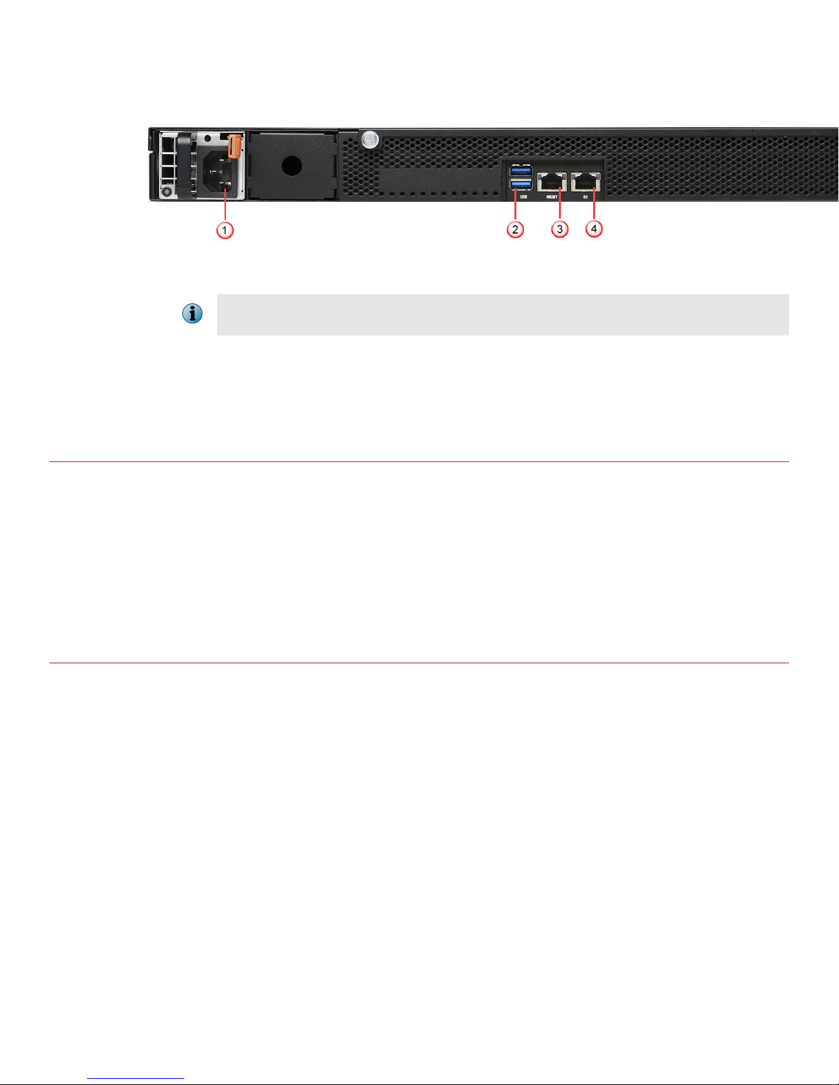
Figure 2 Sensor rear panel
1
Power supply inlet (2)
The NS5x00 Sensors are shipped with one power supply unit. A second power supply (optional) is supported
to enable redundancy.
2
USB ports (2)
3
RJ-45 10/100/1000 Management port (MGMT) (1)
4
RJ-45 10/100/1000 Response port (R1) (1)
Verify the contents in the box
The following accessories are shipped in the NS5x00 Sensor crate:
• Sensor
• Power cords (McAfee provides standard and international power cables)
• Set of rack mounting rails
• Printed Quick Start Guide
Verify the hardware and software requirements
Make sure to meet the following hardware requirements. For more information, see the McAfee Network Security
Platform Installation Guide.
The following are the system requirements for a Manager server.
2
Page 3
Operating
system
Minimum required Recommended
Any of the following:
• Windows Server 2008 R2 Standard or Enterprise Edition, English
Same as the minimum
required.
operating system, SP1 (64-bit) (Full Installation)
• Windows Server 2008 R2 Standard or Enterprise Edition, Japanese
operating system, SP1 (64-bit) (Full Installation)
• Windows Server 2012 Standard Edition (Server with a GUI) English
operating system
• Windows Server 2012 Standard Edition (Server with a GUI)
Japanese operating system
• Windows Server 2012 R2 Standard Edition (Server with a GUI)
English operating system
• Windows Server 2012 R2 Standard Edition (Server with a GUI)
Japanese operating system
• Windows Server 2012 R2 Datacenter Edition (Server with a GUI)
English operating system
• Windows Server 2012 R2 Datacenter Edition (Server with a GUI)
Japanese operating system
Only x64 architecture is supported.
Memory 8 GB 8 GB or more
CPU Server model processor such as Intel Xeon Same
Disk space 100 GB 300 GB or more
Network 100 Mbps card 1000 Mbps card
Monitor 32-bit color, 1440 x 900 display setting 1440 x 900 (or above)
The following are the system requirements for client systems connecting to the Manager application.
Minimum Recommended
Operating
• Windows 7 English or Japanese
system
• Windows 8 English or Japanese
• Windows 8.1 English or Japanese
• Windows 10 English or Japanese
The display language of the Manager client must be same as
that of the Manager server operating system.
RAM 2 GB 4 GB
CPU 1.5 GHz processor 1.5 GHz or faster
Browser
• Internet Explorer 9, 10 or 11
• Mozilla Firefox
• Internet Explorer 11
• Mozilla Firefox 41.0.2 or
above
Google Chrome in not supported since the NPAPI plug-in is
disabled by default and will not be supported by Google going
forward. This means that Java applet support is also disabled
by default.
3
Page 4

Install the following software:
• Sensor image
• Manager image
• Signature set
Install the slide rails and rack mount the Sensor
McAfee recommends rack-mounting your Sensor. For maintenance purposes, you must have access to the
front and rear of the Sensor.
Before you mount the Sensor on the rack, make sure that the power is o. Remove the power cable and all
network interface cables from the Sensor.
Due to the weight of the appliance, McAfee recommends that one person hold the chassis and the other person
x it to the rail cabinet.
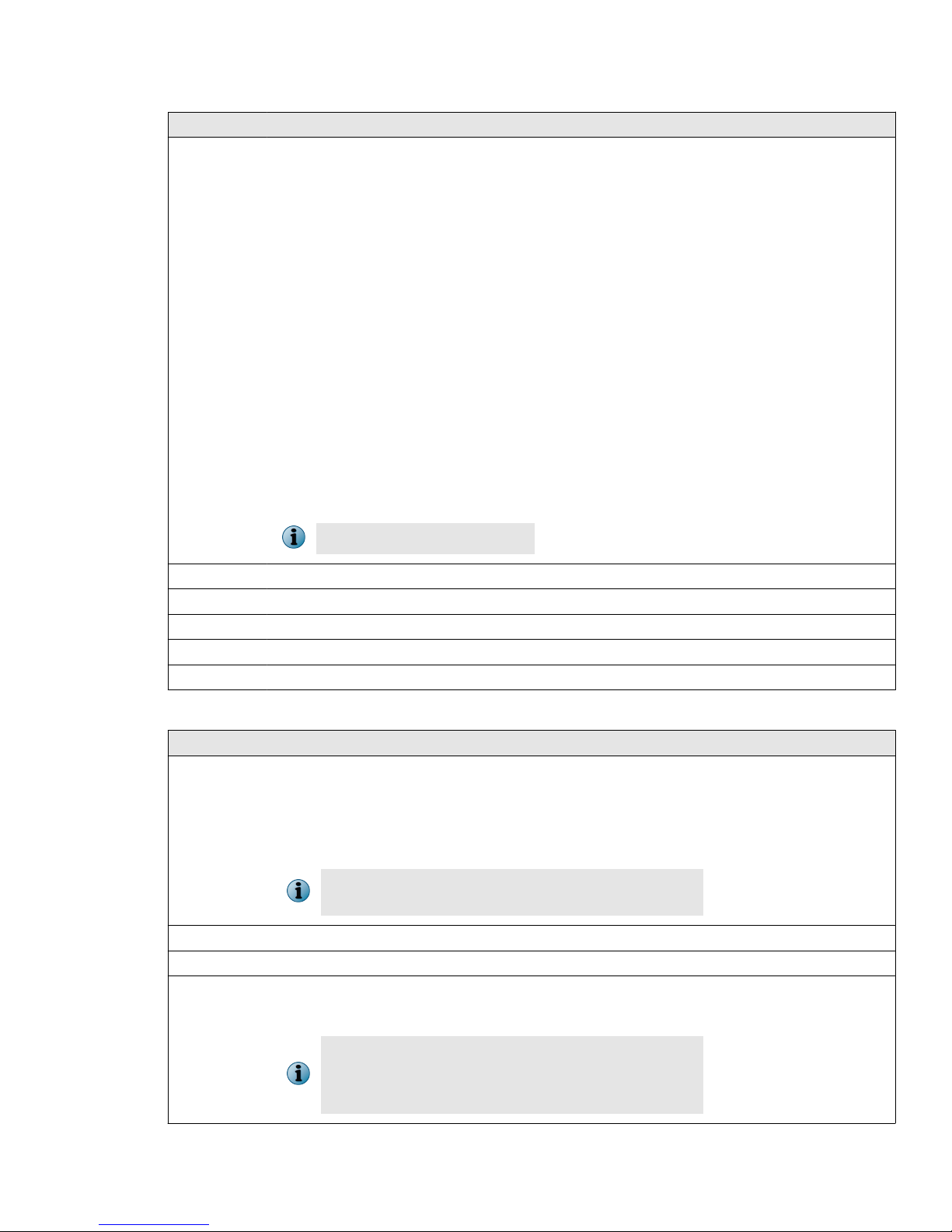
Task
Mount the slide rails to the rack.
1
Align the rails and t it into the corresponding holes on the front post of the rack.
a
Fit the rails into holes on the rear post of the rack.
b
Install the front end of each slide rail in the front post of a 4-post enterprise rack. Try dierent hole
c
combinations until one of them locks in.
At times in a 4-post enterprise rack, certain hole combinations do not permit the rail latch to lock in. So to
make it lock, you must try dierent hole combinations.
4
Page 5
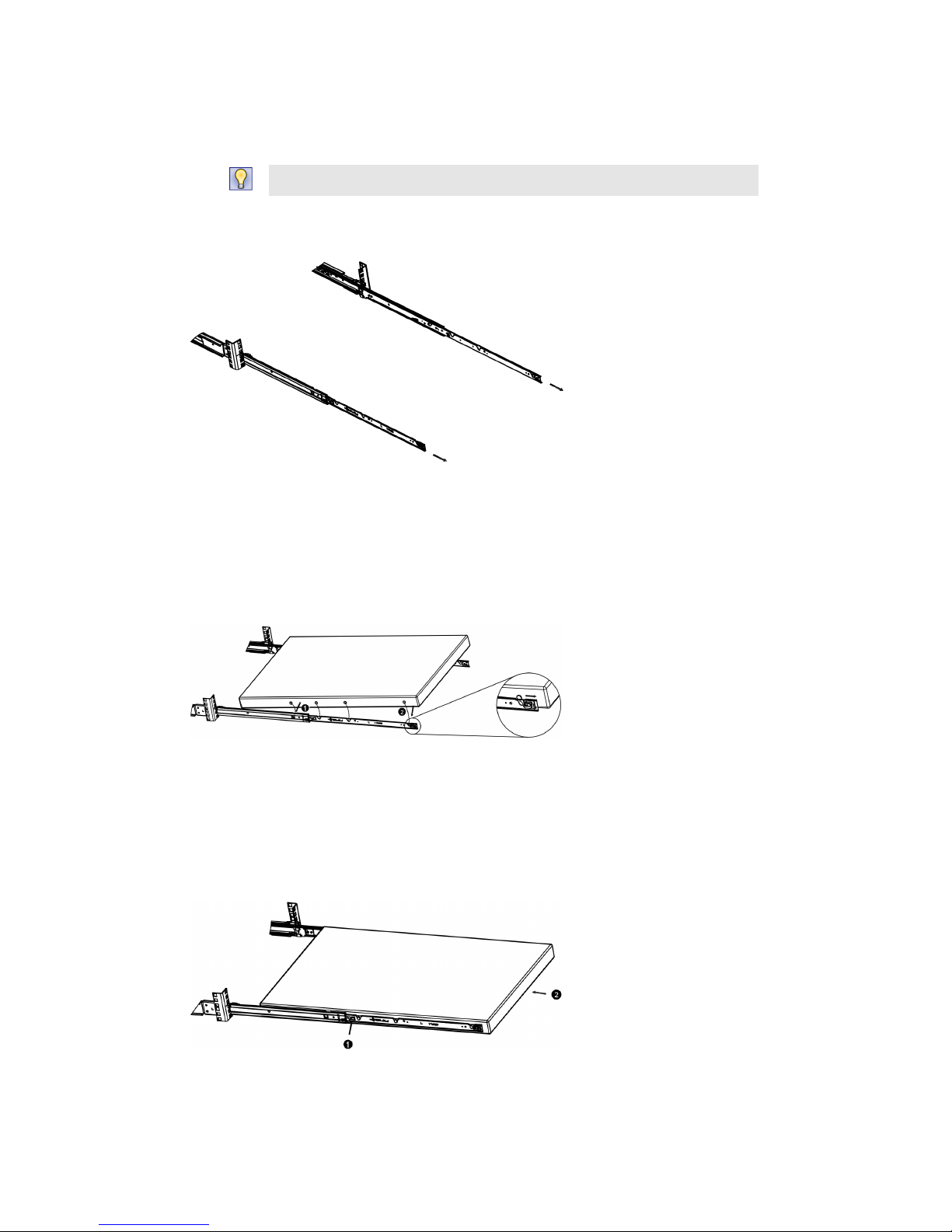
Position the inner members to x the chassis.
2
Pull inner member of the slide rail out until it comes to a lock position.
a
To push the inner member into the rack, lift the latch and push the inner member.
Position both inner members.
b
Mount inner members to the chassis unit.
3
Place each inner member on both sides of the chassis unit. Position the mounting holes of the inner
a
member with matching mounting hooks on chassis unit.
Apply to both sides of chassis unit.
b
Install chassis unit into the rack.
4
Lift the release tab on both sides and push the inner members into the outer members until they lock in
a
place.
Continue to push the chassis unit in until fully closed.
b
5
Page 6

Secure the chassis unit through the rack rails.
5
With the chassis unit in fully closed position, secure using two spring screws provided in the chassis ear.
a
Tighten the screws. The screws thread directly to the rack posts.
b
Connect the Management and Console ports
Task
On the rear panel of the NS5x00 Sensors, plug a Category 5e Ethernet cable in the Management port
1
(labeled MGMT).
Plug the other end of the cable into the network device connected to your Manager server.
2
On the front panel of the NS5x00 Sensors, plug the DB9 Console cables into the Console port (labeled
3
Console).
Connect the other end of the Console port cable directly to a COM port of the PC or terminal server you are
4
using to congure the Sensor (for example, a PC running correctly congured Windows Hyperterminal
software). You must directly connect to the console for initial conguration, you cannot congure the Sensor
remotely.
Terminal servers are provided for console access.
6
Page 7

The required settings for Hyperterminal are:
• Baud rate: 115200 • Stop Bits: 1
• Number of Bits: 8 • Control Flow: None
• Parity: None
Plug one end of the power cable into the power inlet and plug the other end into a power source. The
5
Sensor ships with standard US power and international cables.
The NS-series Sensor does not have a power switch. You can directly plug the power cable into a power
source.
Connect the monitoring ports
This procedure describes how to connect cables to a Sensor that runs in inline mode.
Task
Plug the cable appropriate for use with your transceiver module into one of the monitoring ports labeled x
1
(for example, 1).
Plug the cable appropriate for use with your transceiver module into one of the monitoring ports labeled y
2
(for example, 2).
Connect the other end of each cable to the network devices that you want to monitor. For example, if you
3
plan to monitor trac between a switch and a router, connect the cable connected to 1 to the router and
the one connected to 2 to the switch.
Install the Manager software
For detailed instructions, see the McAfee Network Security Platform Installation Guide.
You must have administrator rights on the target Windows Server to install the Manager software.
A MySQL database is included with the Manager and is installed (embedded) automatically on your target
Windows Server during this process.
7
Page 8

The following steps briey explain the Manager installation:
Task
Prepare the system according to the requirements outlined in McAfee Network Security Platform Installation
1
Guide and the McAfee Network Security Platform Release Notes.
Close all open applications.
2
Go to the McAfee Update Server (https://menshen1.intruvert.com/) and log on, using the grant number and
3
password.
4 Go to the Manager Software Updates folder and select the latest Manager software version available.
Download the .zip le to the target Windows Server and extract the setup le.
5
6 Double-click Manager _<version>_setup.exe and follow the on-screen prompts.
Start the Manager
From the Start menu, select Programs | McAfee | Network Security Manager | Network Security Manager.
Add the Sensor to the Manager
The Manager displays the Logon page.
Task
Log on to the Manager using the default user name (admin) and password (admin123).
1
2 Click the Devices tab.
8
Page 9

3 Select the admin domain from the Domain drop-down. To add a Sensor in the Manager, select Global | Add and
Remove Devices, then click New.
You do not require a license le to enable IPS on NS-series Sensors.
The Add and Remove Devices page is displayed. We recommend using the Add Device wizard to add a device.
Enter the following mandatory information in the appropriate elds.
4
•
Device Name — The Sensor name must begin with a letter. The maximum length of the name is 25
characters.
•
Device Type —
•
Shared Secret — The shared secret must be a minimum of 8 characters and maximum of 25 characters in
Species the type of device to be added. Select IPS Sensor.
length. The key cannot start with an exclamation mark nor can have any spaces. The parameters that
you can use to dene the key are:
• 26 alphabets: Uppercase and lowercase (A,
B, C,...Z and a,b,c,...z)
• 32 symbols: ~ ` ! @ # $ % ^ & * ( ) _ + ‑ = [ ]
{ } \ | ; : " ' , . <? /
• 10 digits: 0 1 2 3 4 5 6 7 8 9
Retype the password in Confirm Shared Secret.
The Sensor name and shared secret key that you enter in the Manager must be identical to the shared
secret that you will later enter during physical installation or initialization of the Sensor (using CLI
interface) in Step 9 - Congure Sensor information. If not, the Sensor will not be able to register itself with
the Manager.
•
Updating Mode — Select Online or Offline.
Selecting Offline enables Oine Sensor update. Online is the default mode.
9
Page 10

•
Contact Information — (Optional) Type the contact information.
•
Location — (Optional) Type the location.
5 Click Save. The added Sensor is displayed on the Add and Remove Devices page.
Congure Sensor information
Congure the Sensor with the network information, a name, and the shared secret key that the Sensor uses to
establish secure communication with the Manager. Use the name and key values you set in Step 8- Add the
Sensor to the Manager.
The rst time you congure a Sensor, you must have physical access to the Sensor.
At any time during conguration, you can type a question mark (?) to get help on the Sensor CLI commands. For
a list of all commands, type commands.
Task
Log on to the Sensor using the terminal connected to the Console port.
1
At the prompt, log on using the default Sensor user name (admin) and password (admin123).
2
Optional, but recommended. Change the Sensor password. At the prompt, type: passwd.The Sensor prompts
3
you to enter the new password and prompts you for the old password.
A password must contain between 8–25 characters, is case sensitive, and can consist of any alphanumeric
character or symbol.
Set the name of the Sensor:
4
You can enter the setup command at the prompt. This automatically prompts you to provide the information
shown in items d through g and item j. Alternatively, you can use the set command. If you use the set
command, manually enter the complete command syntax as shown in items d through g and item j.
At the prompt, type: set sensor name <word>.
Example: set sensor name HR_sensor1
The Sensor name is a case-sensitive character string up to 25 characters. The string can include hyphens,
underscores, and periods, and must begin with a letter.
10
Page 11

If the Sensor is not on the same network as the Manager, set the address of the default Gateway. At the
5
prompt, type: set sensor gateway <A.B.C.D>
Example: set sensor gateway 192.1.1.1
Set the IP address of the Manager server. At the prompt, type: set manager ip <A.B.C.D>.
6
Example: set manager ip 192.2.2.2
Set the IP address and subnet mask of the Sensor. At the prompt, type: set sensor ip <A.B.C.D>
7
<E.F.G.H>.
Example: set sensor ip 192.3.3.3 255.255.255.0
Specify an IP address using four octets separated by periods: X.X.X.X, where X is a number between 0 and
255, followed by a subnet mask in the same format.
If prompted, reboot the Sensor. Type: reboot
8
The Sensor can take up to ve minutes to complete its reboot.
Ping the Manager from the Sensor to determine if your conguration settings to this point have successfully
9
established the Sensor on the network. At the prompt, type:
ping <manager IP address>.
If the ping is successful, continue with the following steps. If not, type show to verify your conguration
settings and check that the information is correct.
Set the shared secret key value for the Sensor. At the prompt, type:
10
set sensor sharedsecretkey
The Sensor then prompts you to enter and then conrm the shared secret key value.
This value is used to establish a trust relationship between the Sensor and the Manager. The secret key value
can be between 8 and 25 characters of any ASCII text. The shared key value is case-sensitive. Make sure that
the value matches the shared secret key value you provided in the Manager interface in Step 8- Add the Sensor
to the Manager.
To verify the
11
To exit the session, type exit.
12
conguration information, type show. Check that all information is correct.
11
Page 12
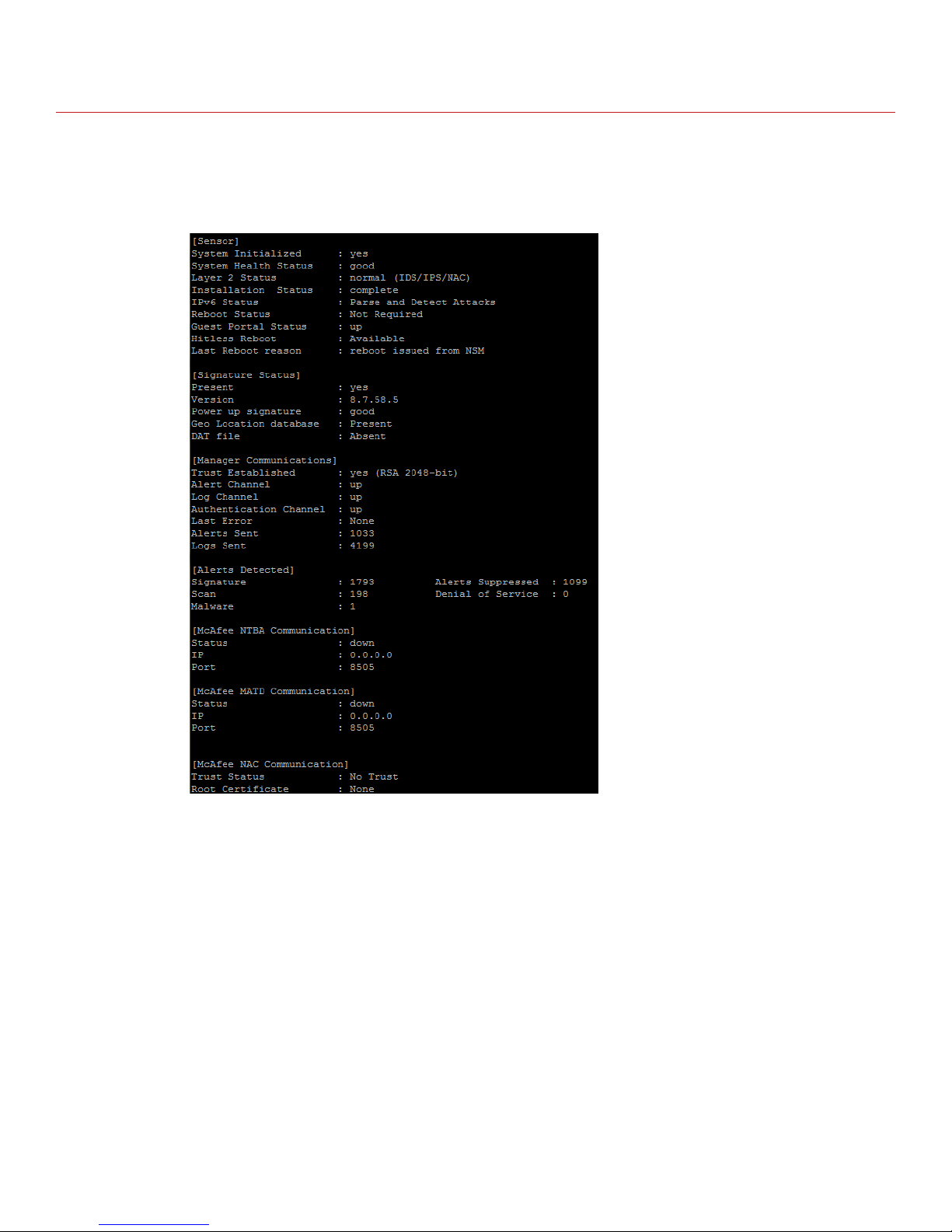
Verify successful installation
Task
In the Sensor CLI, type: status. The status report is displayed.
1
The Sensor parameter System Initialized must be yes, and for Manager communication Trust
Established must be yes.
12
Page 13

2 From the Manager Dashboard, view the Manager status in the System Health monitor.
The Manager status displays as Up and Sensor status is Active.
3 From the Manager, select Devices | <Admin Domain Name> | Devices | <Device Name> | Setup | Physical Ports to
open the ports page.
<Device Name> indicates the name of the Sensor you added.
13
Page 14

4 A policy named Default Inline IPS is active upon Sensor addition. To view this policy, select Policy | <Admin
Domain Name> | Intrusion Prevention | IPS Policies. Select Default Inline IPS from the list and click View / Edit.
The Default Inline IPS policy contains attacks already congured with a "blocking" Sensor response action. If
any attack in the policy is triggered, the Sensor automatically blocks the attack. To tune this or any other
McAfee-provided policies, you can clone the policy and then customize it as described in the McAfee Network
Security Platform IPS Administration Guide.
5 Select Devices | <Admin Domain Name> | Devices | <Device Name> | Setup | Physical Ports.
Select the port on the Sensor that you cabled to view port settings. Make sure that your port settings match
6
the cabling, for example, if port 1 is cabled for inline mode, then the Operating Mode in the port setting must
be inline mode.
For more information on port settings, see Conguring the monitoring and response ports of a Sensor chapter in
the McAfee Network Security Platform IPS Administration Guide.
You're up and running!
Your Sensor is actively monitoring connected segments and communicating with the Manager for
administration and management operations.
Task
For detailed usage instructions, see the McAfee Network Security Platform IPS Administration Guide, or click the
1
Detailed Help buttons in the upper-right corner of each window in the Manager.
2 Start the Analysis | Threat Analyzer to view alert statistics as attacks are detected. A summary of alerts is
displayed in the Unacknowledged Alert Summary area of the Manager Dashboard page.
Having problems? See the McAfee Network Security Platform Troubleshooting Guide for troubleshooting
3
information.
Most deployment problems stem from
4
conguration mismatches between the Sensor and the network
devices to which it is connected. Check the duplex and auto-negotiation settings on both devices to ensure
that they are synchronized.
To contact technical support, go to https://support.mcafee.com.
Copyright © 2017 McAfee, LLC
McAfee and the McAfee logo are trademarks or registered trademarks of McAfee, LLC or its subsidiaries in the US and other countries. Other
marks and brands may be claimed as the property of others.
14
700-4497C00
 Loading...