

Page 1
Revision B
McAfee Network Security Platform
(NS3500 Quick Start Guide)
This quick start guide explains how to quickly set up and activate your McAfee® Network Security Platform NS3500
Sensor in inline mode. This model has a throughput of 100 Mbps and 200 Mbps depending on the license
purchased.
All product documentation referenced in this quick start guide is found on the McAfee Documentation and McAfee
Service Portal.
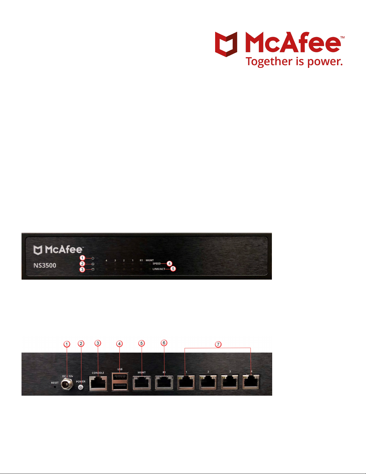
The NS3500 Sensor model
Figure 1 Sensor front panel
Power LED
1
Status LED
2
Hard drive LED
3
Figure 2 Sensor rear panel
Power supply (12V DC IN)
1
Power switch
2
Speed LED for each ethernet port
4
Link LED for each ethernet port
5
1
Page 2

RJ-45 Console port (1)
3
USB ports (2)
4
RJ-45 10/100/1000 Management port (MGMT) (1)
5
RJ-45 10/100/1000 Response port (R1) (1)
6
RJ-45 10/100/1000 Mbps Ethernet Monitoring ports (4)
7
1 Verify the contents in the box
The following accessories are shipped in the NS3500 Sensor crate:
• Sensor
• 12V DC adapter with power cord
• Printed Quick Start Guide
• RJ45 to DB9 console cable
• Set of rack mounting ears with screws
• Set of rubber feet (4x)
The set of rubber feet can be used if the Sensor is placed in a desktop setting.
2 Verify the hardware and software requirements
Make sure to meet the following hardware requirements. For more information, see the McAfee Network
Security Platform Installation Guide.
2
Page 3
The following are the system requirements for a Manager and Central Manager server:
Minimum required Recommended
Operating
system
Any of the following:
• Windows Server 2008 R2 Standard or Enterprise Edition,
English operating system, SP1 (64-bit) (Full Installation)
• Windows Server 2008 R2 Standard or Enterprise Edition,
Japanese operating system, SP1 (64-bit) (Full Installation)
• Windows Server 2012 R2 Standard Edition (Server with a
GUI) English operating system
• Windows Server 2012 R2 Standard Edition (Server with a
GUI) Japanese operating system
• Windows Server 2012 R2 Datacenter Edition (Server with a
GUI) English operating system
• Windows Server 2012 R2 Datacenter Edition (Server with a
GUI) Japanese operating system
• Windows Server 2016 Standard Edition (Server with a GUI)
English operating system
• Windows Server 2016 Standard Edition (Server with a GUI)
Japanese operating system
• Windows Server 2016 Datacenter Edition (Server with a
GUI) English operating system
Windows Server 2016
Standard Edition operating
system
• Windows Server 2016 Datacenter Edition (Server with a
GUI) Japanese operating system
Only X64 architecture is supported.
Memory 8 GB
Supports up to 3 million alerts in Solr.
>16 GB
Supports up to 10
million alerts in
Solr.
CPU Server model processor such as Intel Xeon Same
Disk space 100 GB 300 GB or more
Network 100 Mbps card 1000 Mbps card
Monitor 32-bit color, 1440 x 900 display setting 1440 x 900 (or above)
The following are the system requirements for client systems connecting to the Manager application.
3
Page 4
Minimum Recommended
Operating
system
RAM 2 GB 4 GB
CPU 1.5 GHz processor 1.5 GHz or faster
Browser
• Windows 7, English or Japanese
• Windows 8, English or Japanese
• Windows 8.1, English or Japanese
• Windows 10, English or Japanese
The display language of the Manager client must be
same as that of the Manager server operating
system.
• Internet Explorer 10, 11
• Mozilla Firefox
• Google Chrome (App mode in Windows 8 is not
supported)
To avoid the certicate mismatch error and security
warning, add the Manager web certicate to the
trusted certicate list.
Windows 10, English or
Japanese
• Internet Explorer 11
• Mozilla Firefox 20.0 or
later
• Google Chrome 24.0 or
later
Install the following software:
• Sensor image
• Manager image
• Signature set
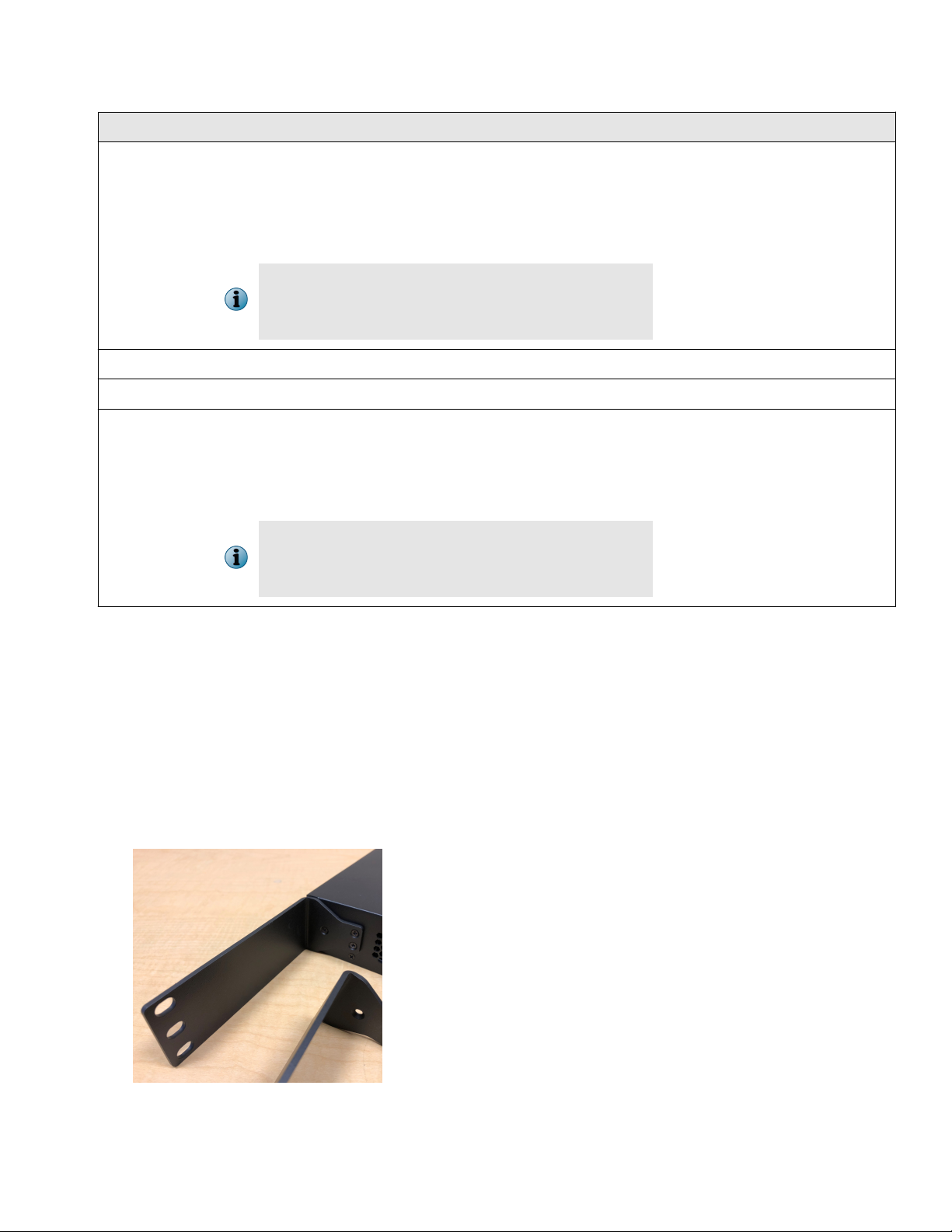
3 Install the Sensor on the rack
Follow this procedure to install the Sensor on the rack.
Attach the ear to the Sensor using three countersink screws.
a
4
Page 5
Secure the Sensor into the rack using four truss head screws.
b
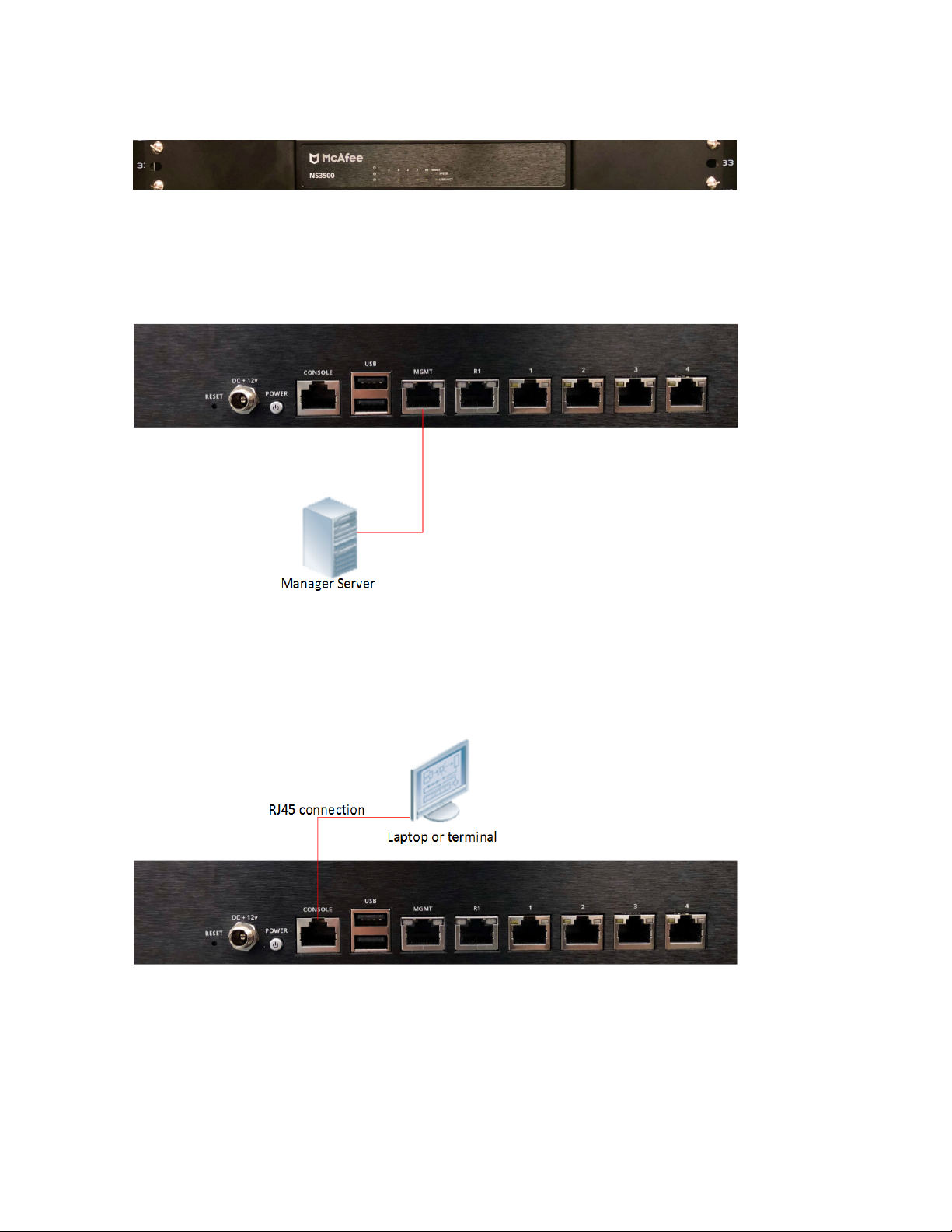
4 Connect the Management and Console ports
On the back panel of the NS3500 Sensors, plug a Category 5e Ethernet cable in the Management port
a
(labeled MGMT).
Plug the other end of the cable into the network device connected to your Manager server.
b
On the back panel of the NS3500 Sensor, plug the RJ45 end of the console cable into the console port
c
(labeled CONSOLE).
Connect the other end of the Console port cable directly to a COM port of the PC or terminal server you
d
are using to congure the Sensor (for example, a PC running correctly congured Windows
Hyperterminal software). You must directly connect to the console for initial conguration, you cannot
congure the Sensor remotely.
5
Page 6

Terminal servers are provided for console access. The required settings for Hyperterminal are:
• Baud rate: 115200 • Stop Bits: 1
• Number of Bits: 8 • Control Flow: None
• Parity: None
Plug the power adapter jack to power inlet connector (labeled DC + 12v) on the back panel of the sensor
e
and turn the screw lock until the jack is fully secured.
Connect one end of the power cord to the adapter and other end to power source.
5 Connect the monitoring ports
This procedure describes how to connect cables to a Sensor that runs in inline mode.
Plug the Category 5e Ethernet cable into one of the monitoring ports labeled x (for example, 1).
a
Plug the Category 5e Ethernet cable into one of the monitoring ports labeled y (for example, 2).
b
Connect the other end of each cable to the network devices that you want to monitor. For example, if you
c
plan to monitor trac between a switch and a router, connect the cable connected to 1 to the router and
the one connected to 2 to the switch.
6 Install the Manager software
For detailed instructions, see the McAfee Network Security Platform Installation Guide.
You must have administrator rights on the target Windows Server to install the Manager software.
A MySQL database is included with the Manager and is installed (embedded) automatically on your
target Windows Server during this process.
6
Page 7

The following steps briey explain the Manager installation:
Prepare the system according to the requirements outlined in McAfee Network Security Platform Installation
a
Guide and the McAfee Network Security Platform Release Notes.
Close all open applications.
b
Go to the McAfee Update Server (https://menshen1.intruvert.com) and log on, using the grant number
c
and password.
d Go to the Manager Software Updates folder and select the latest Manager software version available.
Download the .zip le to the target Windows Server and extract the setup le.
e
Double-click Manager_<version>_setup.exe and follow the on-screen prompts.
f
7 Start the Manager
From the Start menu, select Programs | McAfee | Network Security Manager | Network Security Manager.
8 Add the Sensor to the Manager
After a Sensor is congured with a name and shared key value, you can add the Sensor to the Manager in Add
and Remove Devices page.
Adding a physically installed and network-connected Sensor to the Manager activates communication
between them.
The following steps describe how to add a Sensor to the Manager:
Start the Manager software.
a
Log on to the Manager (the default username is admin and the default password is admin123).
b
c To add a Sensor in the Manager, click Devices | <Admin Domain> | Global | Add and Remove Devices, then click
New.
You do not require a license le to enable IPS on NS-series Sensors.
The Add New Device page is displayed.
7
Page 8

Enter the following mandatory information in the appropriate elds.
d
1) Device Name — The Sensor name must begin with a letter. The maximum length of the name is 25
characters.
2) Device Type —
3) Shared Secret — The shared secret must be a minimum of 8 characters and maximum of 25
characters in length. The key cannot start with an exclamation mark nor can have any spaces. The
parameters that you can use to dene the key are:
• 26 alphabets: Uppercase and lowercase
(A, B, C,...Z and a,b,c,...z)
• 10 digits: 0 1 2 3 4 5 6 7 8 9
4) Confirm Shared Secret — Conrm the shared secret key.
5) Updating Mode — Select Online or Offline.
e Click Save. The added Sensor is displayed in the Add and Remove Devices page.
Species the type of device to be added. Select IPS Sensor.
• 32 symbols: ~ ` ! @ # $ % ^ & * ( ) _ + ‑ =
[ ] { } \ | ; : " ' , . <? /
The Sensor name and shared secret key entered in the Manager must be identical to the
shared secret entered later during physical installation or initialization of the Sensor (using
CLI) in Step 10 - Congure Sensor information. If not, the Sensor will not be able to register
itself with the Manager.
Selecting Offline enables Oine Sensor update. Online is the default mode.
9 Congure Sensor information
Congure the Sensor with the network information, a name, and the shared secret key that the Sensor uses to
establish secure communication with the Manager. Use the name and key values you set in Step 8- Add the
Sensor to the Manager.
The rst time you congure a Sensor, you must have physical access to the Sensor.
8
Page 9

At any time during conguration, you can type a question mark (?) to get help on the Sensor CLI commands.
For a list of all commands, type commands.
Log on to the Sensor using the terminal connected to the Console port.
a
At the prompt, log on using the default Sensor user name admin and password admin123.
b
Optional, but recommended. Change the Sensor password. At the prompt, type: passwd. The Sensor
c
prompts you to enter the new password and prompts you for the old password.
A password must contain between 8 to 25 characters, is case-sensitive, and can consist of any
alphanumeric character or symbol.
Set the name of the Sensor.
d
You can enter the setup command at the prompt. This automatically prompts you to provide
the information shown in items d through g and item j. Alternatively, you can use the set
command. If you use the set command, manually enter the complete command syntax as
shown in items d through g and item j.
At the prompt, type: set sensor name <word>.
Example: set sensor name HR_sensor1
The Sensor name is a case-sensitive character string up to 25 characters. The string can include
hyphens, underscores, and periods, and must begin with a letter.
If the Sensor is not on the same network as the Manager, set the address of the default Gateway. At the
e
prompt, type: set sensor gateway <A.B.C.D>
Example: set sensor gateway 192.1.1.1
Set the IP address of the Manager server. At the prompt, type: set manager ip <A.B.C.D>.
f
Example: set manager ip 192.2.2.2
9
Page 10

Set the IP address and subnet mask of the Sensor. At the prompt, type: set sensor ip <A.B.C.D>
g
<E.F.G.H>.
Example: set sensor ip 192.3.3.3 255.255.255.0
Specify an IP address using four octets separated by periods: X.X.X.X, where X is a number
between 0 and 255, followed by a subnet mask in the same format.
If prompted, reboot the Sensor. Type: reboot
h
The Sensor can take up to ve minutes to complete its reboot.
Ping the Manager from the Sensor to determine if your conguration settings to this point have
i
successfully established the Sensor on the network. At the prompt, type:
ping <manager IP address>.
If the ping is successful, continue with the following steps. If not, type show to verify your conguration
settings and check that the information is correct.
Set the shared secret key value for the Sensor. At the prompt, type:
j
set sensor sharedsecretkey
The Sensor then prompts you to enter and then conrm the shared secret key value.
This value is used to establish a trust relationship between the Sensor and the Manager. The
secret key value can be between 8 and 25 characters of any ASCII text. The shared key value is
case-sensitive. Make sure that the value matches the shared secret key value you provided in
the Manager interface in Step 8- Add the Sensor to the Manager.
To verify the conguration information, type show. Check that all information is correct.
k
A license is required to activate the baseline throughput of 100 Mbps for NS3500 Sensor. A
dierent license is required to increase the throughput from 100 Mbps to 200 Mbps. For more
information on license, see McAfee Network Security Platform NS3500 Sensor Product Guide.
To exit the session, type exit.
l
10
Page 11

10 Verify successful installation
In the Sensor CLI, type: status. The status report is displayed.
a
The Sensor parameter System Initialized must be yes, and for Manager communication Trust
Established must be yes.
b From the Manager Dashboard, view the Manager status in the System Health monitor.
11
Page 12

The Manager status displays as Up and Sensor status is Active.
c From the Manager, select Devices | <Admin Domain Name> | Devices | <Device Name> | Setup | Physical Ports to
open the ports page.
<Device Name> indicates the name of the Sensor you added.
d A policy named Default Prevention is active upon Sensor addition. To view this policy, select Policy |
<Admin Domain Name> | Intrusion Prevention | Policy Types | IPS Policies. Select Default Prevention from the list and
click Edit.
The Default Prevention policy contains attacks already congured with a "blocking" Sensor
response action. If any attack in the policy is triggered, the Sensor automatically blocks the
attack. To tune this or any other McAfee-provided policies, you can clone the policy and then
customize it as described in the McAfee Network Security Platform IPS Administration Guide.
e Select Devices | <Admin Domain Name> | Devices | <Device Name> | Setup | Physical Ports.
Select the port on the Sensor that you cabled to view port settings. Make sure that your port settings
f
match the cabling, for example, if port 1 is cabled for inline mode, then the mode of operation in the port
setting must be inline mode.
For more information on port settings, see Conguring the monitoring and response ports of a
Sensor chapter in the McAfee Network Security Platform IPS Administration Guide.
11 You're up and running!
Your Sensor is actively monitoring connected segments and communicating with the Manager for
administration and management operations.
For detailed usage instructions, see McAfee Network Security Platform IPS Administration Guide, or click
a
the ? buttons in the upper-right corner of each window in the Manager.
b Start the Analysis | <Admin Domain Name> | Attack Log to view alert statistics as attacks are detected. A
summary of alerts is displayed in the Unacknowledged Alert Summary monitor of the Manager Dashboard page.
12
Page 13

Having problems? Check McAfee Network Security Platform Troubleshooting Guide for troubleshooting
c
information.
Most deployment problems stem from conguration mismatches between the Sensor and the network
d
devices to which it is connected. Check your duplex and auto-negotiation settings on both devices to
ensure they are synchronized.
If you need to contact Technical Support, go to https://mysupport.mcafee.com.
131415
Page 14

Page 15

Page 16

Copyright © 2019 McAfee, LLC
McAfee and the McAfee logo are trademarks or registered trademarks of McAfee, LLC or its subsidiaries in the US and other countries. Other
marks and brands may be claimed as the property of others.
16 700-5145B00
 Loading...