

McAfee IIP-M80K-ISAA, M-8000 Quick Start Manual

IntruShield® M-8000 Quick Start Guide
Setting up an M-8000 sensor
This Quick Start Guide explains how to quickly set up and activate
your McAfee IntruShield M-8000 sensor in in-line mode. Cabling the
sensor’s XFP (10 Gigabit Small Form-factor Pluggable) and SFP
(Small Form-factor Pluggable) Gigabit Ethernet Monitoring ports for
in-line mode enables you to configure the sensor to drop attacks
before they reach their target
Note: If you are setting up your sensor in SPAN or Tap mode, see
the sensor’s Product Guide for cabling instructions.
All product documentation referenced in this Quick Start Guide is
found on the McAfee Documentation Service Portal.
The sensor front panel
Figure 1: Sensor Components
Item Description
1 Power supply A (2—included)
2 Power supply B (2—optional; sold separately)
3 RS-232C Control port (2)
4 RS-232C Auxiliary port (2)
5 RJ-11 Fail-Open Control ports (14)
6 SFP Gigabit Ethernet Monitoring ports (16)
7 XFP 10 Gigabit Ethernet Monitoring ports (12)
8 Compact Flash port (2)
9 RJ-45 Response port (1)
10 10/100/1000 Management port (1)
11 Interconnect ports (6)
IntruShield setup overview
STEP 1: Set up your sensor — In step one, you will perform the
following tasks.
Position the sensor — Attach rails and mounting ears; install
interface modules and, optionally, any redundant power
supplies; install the sensor in a rack.
Cable the Management and Console ports — Connect the
sensor to a console you will use for configuration.
Cable the Monitoring ports — Cable the sensor to monitor a
segment of network traffic in-line.
Cable the Interconnect ports— Connect the primary sensor to
the secondary sensor.
STEP 2: Add the sensor to your Manager — In this step, you will
install the Manager software on your Manager server and then
configure the sensor to communicate with the Manager.
STEP 3: Configure the sensor — In this step, you will configure the
sensor to communicate with the Manager.
Configure the sensor — Configure the sensor with network
information, and establish secure communication with the
Manager.
Verify successful installation — Perform some tasks to verify
communication between the sensor and the Manager.
STEP 1: Set up your sensor
Position the sensor
Details on all of the tasks in Step 1 are available in the
IntruShield Sensor
Configuration Guides
and in the IntruShield Sensor Product Guide for your
sensor model. Also see
IntruShield Slide Rail Assembly Procedure.
1. Release the rails and attach inner rails (of a three-in-one set) to
the chassis by fastening it with the screws provided.
Figure 2: Chassis-to-rail attachment
2. Attach L-shape and external rails to the rack frame.
Figure 3: Mounted rails
3. Install the primary sensor into a rack and mount ears. You can
also mid-mount the sensor (optional).
Figure 4: Rack-mount the sensor
Figure 5: Mid-mount the sensor
4. Install the redundant power supply (optional).
Figure 6: Insert power supply
5. Install modules in the sensor's Monitoring ports.
Figure 7: Install the interface module
6. Repeat Steps 1 through 5 for the secondary sensor.
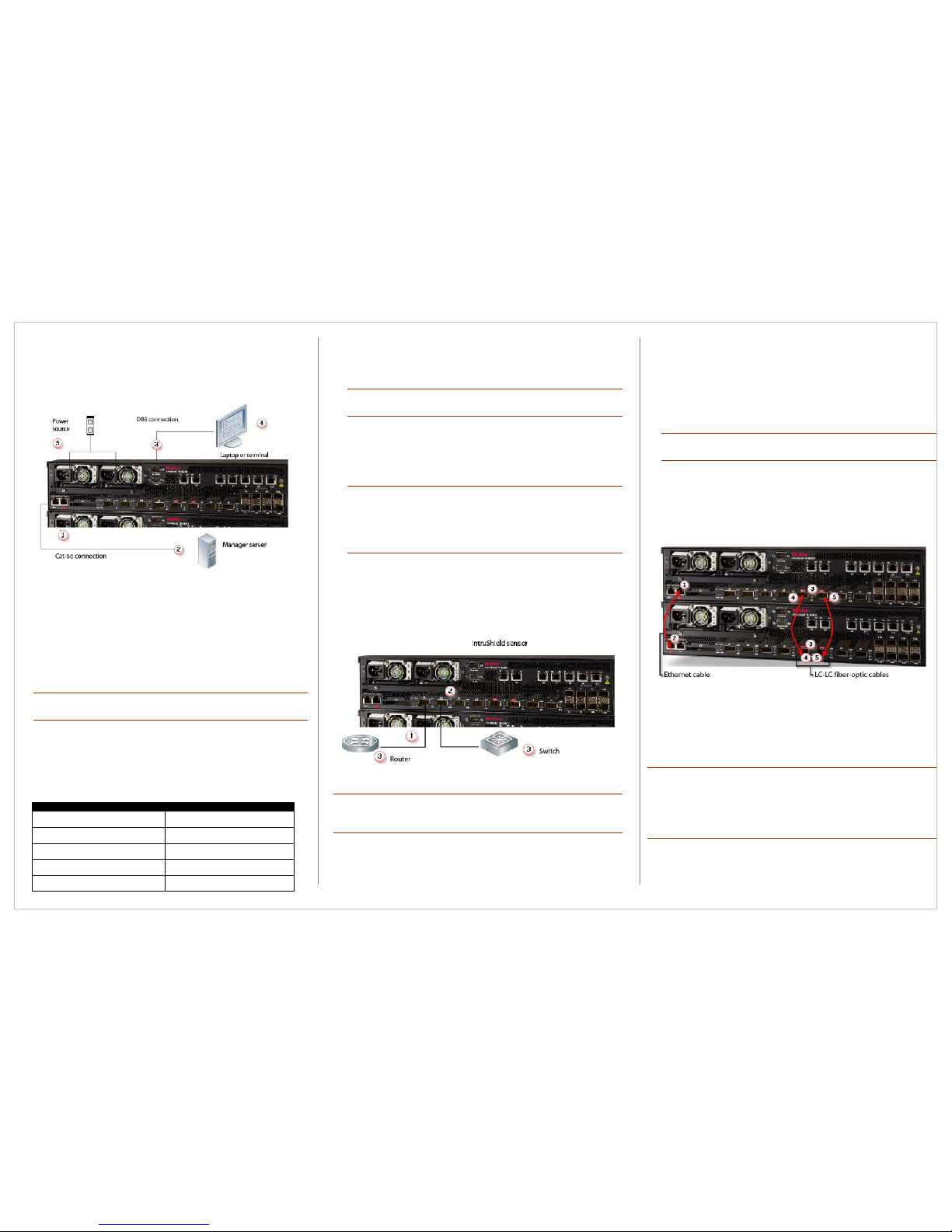
Cable the Management and Console ports
Make sure the sensor is powered OFF before attaching cables.
Figure 8: Sensor setup
1. Plug a Category 5e Ethernet cable in the (Management) Mgmt
port of M-8000 P.
2. Plug the other end of the cable into the network device connected
to your Manager server.
3. Plug the DB9 Console cable supplied in the sensor box into the
Console port (labeled Console on the sensor front panel) of
M-8000 P.
Note: You can use the Console port on the secondary sensor,
M-8000 S, for a flash recovery process or to troubleshoot.
4. Connect the other end of the Console port cable directly to a COM
port of the PC or terminal server you will be using to configure the
sensor (for example, a PC running correctly configured Windows
Hyperterminal software). You must connect directly to the console
for initial configuration; you cannot configure the sensor remotely.
The required settings for Hyperterminal are:
Name Setting
Baud rate 38400
Number of Bits 8
Parity None
Stop Bits 1
Control Flow None
5. Plug the female end of a power cable into the power inlet and plug
the other end into a power source. The sensor ships with standard
US power and international cables.
Note: The M-8000 does not have a power switch; you need only
plug the power cable into a power source.
Cable the Monitoring ports
This procedure describes how to cable a sensor to run in in-line mode.
1. Plug the cable appropriate for use with your XFP or SFP module
into one of the Monitoring ports labeled xA (for example, 1A).
Note: McAfee supports only those SFP/XFP modules purchased
through McAfee or from a McAfee-approved vendor.
Note: Do not use XC ports. These ports are reserved for
interconnection between the primary (M-8000 P) and secondary
(M-8000 S) sensors.
2. Plug another cable into the peer of the port used in Step 1. This
port will be labeled xB (for example, 1B).
3. Connect the other end of each cable to the network devices that
you want to monitor. (For example, if you plan to monitor traffic
between a switch and a router, connect the cable connected to 1A
to the router and the one connected to 1B to the switch.)
Figure 9: Cable sensor for in-line mode
Note: For instructions on how to cable the sensor to run in other
operating modes, see the
IntruShield Sensor Product Guide
for your
sensor model.
Cable the interconnect ports
This procedure describes how to connect the primary sensor to the
secondary sensor.
1. Plug the supplied Ethernet cable into the XC1 port of the primary
sensor.
2. Connect the other end of the Ethernet cable used in Step 1 into
the XC4 port of the secondary sensor.
3. Insert the supplied XFP modules into the XC2, XC3, XC5, and
XC6 ports on the primary and secondary sensors.
Note: McAfee supports only those XFP modules purchased
through McAfee or from a McAfee-approved vendor.
4. Plug one end of an LC-LC fiber-optic cable into the XC2 port of the
primary sensor and connect the other the cable to the XC5 port of
the secondary sensor.
5. Plug one end of an LC-LC fiber-optic cable into the XC3 port of the
primary sensor and connect the other the cable to the XC6 port of
the secondary sensor.
Figure 10: Cable primary sensor to secondary sensor
STEP 2: Add the sensor to your Manager
Install the Manager software
For detailed instructions, refer to the Manager Installation Guide.
Note: You must have Administrator privileges on the target Windows
server to install the Manager software.
A MySQL database is included with the Manager and is installed
(embedded) automatically on your target Windows server during this
process.
1.
Prepare the system according to the requirements outlined in the
Manager Installation Guide and the IntruShield Release Notes.
2.
Close all open applications.
 Loading...