

McAfee M-1250, M-1450 Product Manual

M-1250/M-1450 Sensor Product Guide
Revision D
McAfee® Network Security Platform

COPYRIGHT
Copyright © 2017 McAfee, LLC
TRADEMARK ATTRIBUTIONS
McAfee and the McAfee logo, McAfee Active Protection, ePolicy Orchestrator, McAfee ePO, McAfee EMM, Foundstone, McAfee LiveSafe, McAfee QuickClean, Safe Eyes,
McAfee SECURE, SecureOS, McAfee Shredder, SiteAdvisor, McAfee Stinger, True Key, TrustedSource, VirusScan are trademarks or registered trademarks of McAfee,
LLC or its subsidiaries in the US and other countries. Other marks and brands may be claimed as the property of others.
LICENSE INFORMATION
License Agreement
NOTICE TO ALL USERS: CAREFULLY READ THE APPROPRIATE LEGAL AGREEMENT CORRESPONDING TO THE LICENSE YOU PURCHASED, WHICH SETS FORTH THE
GENERAL TERMS AND CONDITIONS FOR THE USE OF THE LICENSED SOFTWARE. IF YOU DO NOT KNOW WHICH TYPE OF LICENSE YOU HAVE ACQUIRED, PLEASE
CONSULT THE SALES AND OTHER RELATED LICENSE GRANT OR PURCHASE ORDER DOCUMENTS THAT ACCOMPANY YOUR SOFTWARE PACKAGING OR THAT YOU HAVE
RECEIVED SEPARATELY AS PART OF THE PURCHASE (AS A BOOKLET, A FILE ON THE PRODUCT CD, OR A FILE AVAILABLE ON THE WEBSITE FROM WHICH YOU
DOWNLOADED THE SOFTWARE PACKAGE). IF YOU DO NOT AGREE TO ALL OF THE TERMS SET FORTH IN THE AGREEMENT, DO NOT INSTALL THE SOFTWARE. IF
APPLICABLE, YOU MAY RETURN THE PRODUCT TO MCAFEE OR THE PLACE OF PURCHASE FOR A FULL REFUND.
2
McAfee® Network Security Platform M-1250/M-1450 Sensor Product Guide

Contents
1 Introducing Network Security Sensors 7
2 Before you install 11
Preface 5
About this guide ................................... 5
Audience ...................................5
Conventions ..................................5
What's in this guide ...............................6
Find product documentation ...............................6
About the M-1250/M-1450 Sensor ............................ 7
Physical description of the M-1250/M-1450 Sensor ...................... 8
Ports on the Sensor ...............................8
Front panel LEDs on M-1250/M-1450 Sensor ......................9
Usage restrictions .................................. 11
Safety measures ...................................11
Contents of the Sensor box ...............................12
Unpack the Sensor ..................................12
3 Setting up the Sensor 15
Setup overview ................................... 15
Position the Sensor ..................................15
Install the ears on the chassis ...........................15
Mount the Sensor on a rack ........................... 16
Cable the Sensor .................................. 17
Power on the Sensor .................................17
Power o the Sensor ..............................17
4 Attaching cables to the Sensor 19
Cable the Console port ................................ 19
Cable the Auxiliary port ................................ 20
Connect the cable to the Response port ..........................20
Cable the Management port .............................. 21
Cable Monitoring ports ................................ 21
How to use peer ports ............................. 21
Default Monitoring port speed settings ....................... 22
Cable types for routers, switches, hubs, and PCs ....................22
Cable the Sensor to monitor in in-line mode ........................ 23
Cable the Sensor to monitor in SPAN or hub mode ...................... 23
About connecting Sensors for fail-over .......................... 23
Cable M-1250/M-1450 Sensor for failover ...................... 24
A M-1250/M-1450 Sensor specications 25
McAfee® Network Security Platform M-1250/M-1450 Sensor Product Guide
3

Contents
B Regulatory, compliance, and safety information 27
Index 29
4
McAfee® Network Security Platform M-1250/M-1450 Sensor Product Guide

Preface
This guide provides the information you need to congure, use, and maintain your McAfee product.
Contents
About this guide
Find product documentation
About this guide
This information describes the guide's target audience, the typographical conventions and icons used in this
guide, and how the guide is organized.
Audience
McAfee documentation is carefully researched and written for the target audience.
The information in this guide is intended primarily for:
• Administrators — People who implement and enforce the company's security program.
• Users — People who use the computer where the software is running and can access some or all of its
features.
Conventions
This guide uses these typographical conventions and icons.
Italic Title of a book, chapter, or topic; a new term; emphasis
Bold Text that is emphasized
Monospace
Narrow Bold
Hypertext blue A link to a topic or to an external website
Commands and other text that the user types; a code sample; a displayed message
Words from the product interface like options, menus, buttons, and dialog boxes
Note: Extra information to emphasize a point, remind the reader of something, or provide an
alternative method
Tip: Best practice information
Caution: Important advice to protect your computer system, software installation, network,
business, or data
Warning: Critical advice to prevent bodily harm when using a hardware product
McAfee® Network Security Platform M-1250/M-1450 Sensor Product Guide
5

Preface
Find product documentation
What's in this guide
This guide contains information necessary to setup your M-1250/M-1450 Sensor model. This information
includes guiding you through
preconguring, cabling, and troubleshooting your Sensor.
Find product documentation
On the ServicePortal, you can nd information about a released product, including product documentation,
technical articles, and more.
Task
1 Go to the ServicePortal at https://support.mcafee.com and click the Knowledge Center tab.
2 In the Knowledge Base pane under Content Source, click Product Documentation.
3 Select a product and version, then click Search to display a list of documents.
6
McAfee® Network Security Platform M-1250/M-1450 Sensor Product Guide

1
1
Introducing Network Security Sensors
This section describes the McAfee® Network Security Sensors at a high-level and also describes the McAfee
M-1250/M-1450 Network Security Sensor (Sensor) in detail.
Sensors are high-performance, scalable, and exible content processing appliances built for the accurate
detection and prevention of intrusions, misuse, distributed denial of service (DDoS) attacks, and network access
control(NAC) of hosts. When deployed at key access points, a Sensor provides real-time trac monitoring to
detect malicious activity, and respond to the malicious activity as congured by the administrator.
After the Sensor is deployed and communication established, Sensors are congured and managed using the
McAfee Network Security Manager (Manager) server.
The process of conguring a Sensor and establishing communication with the Manager is described in the later
chapters of this guide. The Manager server is described in detail in the McAfee Network Security Platform Manager
Administration Guide.
Contents
About the M-1250/M-1450 Sensor
Physical description of the M-1250/M-1450 Sensor
About the M-1250/M-1450 Sensor
The M-1250 or the M-1450 Sensor provides eective network IPS functionality as well as Network Access
Control (NAC) of hosts.
®
The IPS functionality involves real-time detection and prevention of threats and known, zero-day, or encrypted
attacks. The Sensor can perform many types of attack responses, including generating alerts and packet logs,
resetting TCP connections, "scrubbing" malicious packets, and even blocking attack packets entirely before they
reach the intended target.
Network Access Control of hosts is regulating access to network resources based on host System Health level
(Standard/ DHCP NAC), identity of the user logged into the host (IBAC), or both. The Sensor also provides the
Hybrid NAC functionality where a host is rst subjected to DHCP-NAC and then Standard NAC at dierent ports
of the same Sensor. For more information on the NAC functionality and congurations of the Manager, see the
NAC Administration Guide.
Throughout this guide the terms, 'Sensor' and 'M-1250/M-1450' refer to the M-1250 or the M-1450
Sensor in general.
McAfee® Network Security Platform M-1250/M-1450 Sensor Product Guide
7
1
Introducing Network Security Sensors
Physical description of the M-1250/M-1450 Sensor
Physical description of the M-1250/M-1450 Sensor
The M-1250/M-1450 Sensor is equipped with eight Fast Ethernet ports (or interfaces). M-1250 can monitor up to
100 Mbps, and M-1450 can monitor upto 200 Mbps of aggregated trac respectively. The M-1250/M-1450
Sensor can monitor four 10/100/1000 Mbps Ethernet segments in full-duplex mode (tap or in-line), and eight
segments in half-duplex mode (monitoring SPAN ports or hubs).
Ports on the Sensor
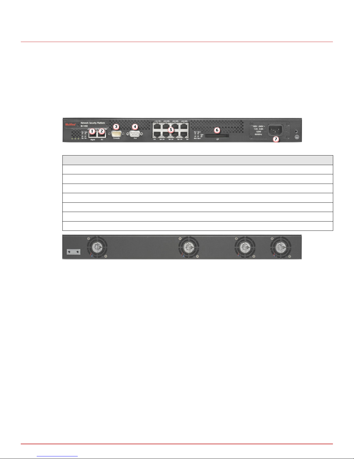
The M-1250/M-1450 Sensor is a one rack-unit (1RU) box equipped with the following ports:
Figure 1-1 M-1450 Sensor Front Panel
Item Description
1 RJ-45 10/100/1000 Management port (1)
2 RJ-45 Response port (1)
3 RS-232C Console port (1)
4 RS-232C Auxiliary port (1)
5 RJ-45 10/100/1000 Ethernet Monitoring ports (8)
6 External Compact Flash port (1)
7 Power supply A (1)
Figure 1-2 M 1450 Sensor back panel
1
One 10/100/1000 Management port, which is used for secure communication with the Manager server.
Communication between the Sensor and the Manager server uses secure channels; these channels provide
link privacy using encryption and mutual authentication between Sensors and the Manager using public key
authentication. You assign an IP address to this Ethernet port during installation.
2
One Response port, which, when you are operating in the SPAN mode, enable you to inject response
packets back into your network, for example, through a switch or router. The Response port is also used in
the tap mode.
3
One RS-232C Console port, which is used to set up and congure the Sensor.
4
One RS-232C Auxiliary port, which may be used to dial in remotely to set up and congure the Sensor.
5
Eight 10/100/1000 Monitoring ports, which enable you to monitor eight SPAN ports or four full-duplex
tapped segments or four segments in-line. When the Sensor operates in the IPS mode, these ports operate
in stealth mode; that is, they have no IP addresses nor even a TCP/IP stack to respond to IPS detection
techniques. This renders them completely invisible to intruders. When operating in the NAC mode, the
monitoring ports can be assigned IP addresses. The monitoring ports for M-1250/M-1450 Sensor are 1A/1B,
2A/2B, 3A/3B and 4A/4B.
8
McAfee® Network Security Platform M-1250/M-1450 Sensor Product Guide
Physical description of the M-1250/M-1450 Sensor
6
One External Compact Flash port. This port is used for two purposes. It is used to control optional
fail-open hardware as described in the Gigabit Optical Fail-Open Bypass Kit Guide. It is also used in
troubleshooting situations where the Sensor's internal ash is corrupted and you must reboot the Sensor
using the external compact ash. For more information, see the on-line KnowledgeBase at http://
mysupport.mcafee.com/Eservice/. Click Search the KnowledgeBase.
7
Power supply. The Sensor power supply port is located on the front side of the Sensor. The supply uses a
standard IEC port (IEC320-C13). McAfee provides a standard, 2m NEMA 5-15P (US) power cable (3 wire).
International customers are provided with a country-appropriate power cable.
Introducing Network Security Sensors
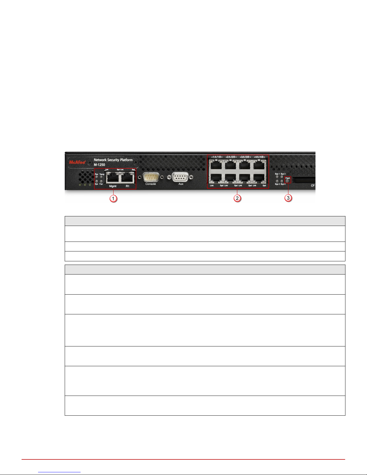
Front panel LEDs on M-1250/M-1450 Sensor
The front panel LEDs provide status information for the health of the Sensor and the activity on its ports.
The image and table that follows describe the operational M-1250/M-1450 front panel LEDs.
1
Figure 1-3 LEDs on the front panel that are used during normal operating conditions
Region in the image LEDs represented here
1 Pwr, Sys, Temp, Fan, Management Port Speed, Management Port Link, Response Port
Speed, Response Port Link
2 10/100/1000 Monitoring Ports Speed, 10/100/1000 Monitoring Ports Link
3 Flash
LED Status Description
Pwr GreenOThe Sensor is powered on and functioning.
The Sensor is powered o.
Sys Green
Amber
Temp Green
Amber
Fan Green
Amber
Management Port Speed Green
Amber
O
Sensor is operating.
Sensor is booting. (It could also indicate a system failure.)
Inlet air temperature measured inside chassis is normal. (Chassis
temperature OK.)
Inlet air temperature measured inside chassis is too hot. (Chassis
temperature too hot.)
Fan is operating.
The fan has failed.
The port speed is 1000 Mbps.
The port speed is 100 Mbps.
The port speed is 10 Mbps.
Management Port Link GreenOThe link is connected.
McAfee® Network Security Platform M-1250/M-1450 Sensor Product Guide
The link is disconnected.
9
 Loading...