

Page 1

This guide describes the features and capabilities of McAfee® Data Loss Prevention (McAfee DLP)
appliances to help you to manage and maintain them.
For information on running and installing McAfee DLP in a virtual environment, see the McAfee Data
Loss Prevention Virtual Installation Guide.
About the appliances
McAfee DLP software runs on these appliance models.
• 1650
Hardware Guide
Revision B
McAfee Data Loss Prevention
1650, 3650, 4400, 5500
• 3650
• 4400
• 5500
Supported software versions
McAfee DLP appliances support these software versions.
• 9.0.x
• 9.2.x
• 9.3.x
1
Page 2

Models and features
The table shows the McAfee DLP models and features.
Table 1 Model features
Model Number of hard
drives
1650 4 500 GB 16 GB No 1U
3650 16 4 TB 16 GB No 3U
4400 12 7.2 TB 24 GB Yes 2U
5500 8 9 TB 32 GB Yes 2U
Capture database
capacity
RAM Remote Management
Module (RMM)
Model 1650
The model 1650 appliance ships on a Supermicro X7DBU system board.
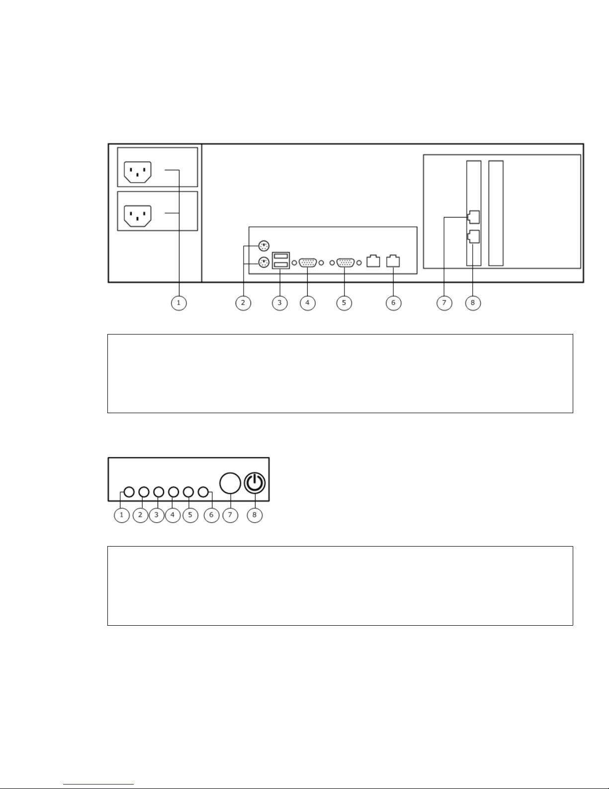
Back panel hardware components
The illustration identifies the hardware components on the back panel of the appliance.
Figure 1 1650 back panel
1
Power supplies
5
VGA port
Rack height
2
PS2 ports
3
USB ports
4
Serial port
Front control panel
The control panel is on the front of the chassis.
Figure 2 1650 front control panel
1
System ID button
2
System overheat/fan failure
3
NIC 2 activity
4
NIC 1 activity
6
Management port
7
Capture port 0
8
Capture port 1
5
Hard drive activity
6
System power
7
Reset button
8
Power button
2
Page 3
Model 3650
The model 3650 appliance ships on a Supermicro X7DBU system board.
Back panel hardware components
The illustration identifies the hardware components on the back panel of the appliance.
Figure 3 3650 back panel
1
Power supplies
2
PS2 ports
3
USB ports
4
Serial port
Front control panel
The control panel is on the front of the chassis.
Figure 4 3650 front control panel
1
System power failure
2
System overheat/fan failure
3
NIC 2 activity
4
NIC 1 activity
5
VGA port
6
Management port
7
Capture port 0
8
Capture port 1
5
Hard drive activity
6
System power
7
Reset button
8
Power button
3
Page 4
Model 4400
The model 4400 appliance ships on an Intel Server System SR2612UR.
For more information on the Intel Server System SR2612UR, see the Intel documentation.
• Intel® Server System SR2612UR Technical Product Specification:
http://download.intel.com/support/motherboards/server/s5520ur/sb/sr2612ur_tps_13.pdf
• Intel® Server System SR2612UR Service Guide:
http://download.intel.com/support/motherboards/server/s5520ur/sb/
r2612ur_service_guide_14.pdf
Back panel hardware components
The illustration identifies the hardware components on the back panel of the appliance.
Figure 5 4400 back panel
1
VGA port
2
USB ports
3
Management port
4
Remote access port (RMM)
On some 4400 models, the capture ports might be on a slotted NIC instead of on the motherboard. In
this case, the capture port numbers are swapped.
Front control panel
The control panel is on the front of the chassis.
Figure 6 4400 front control panel
1
Power supply + 12V OK
2
Enclosure services subsystem fault
5
Capture port 0
6
Capture port 1
7
Power supplies
3
System status
4
System identify
4
Page 5
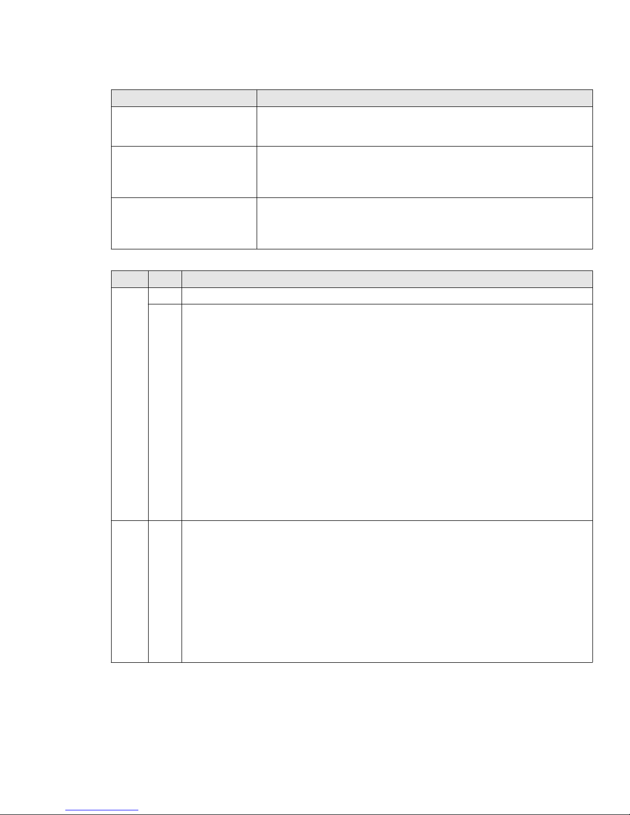
Table 2 4400 indicator light states
Indicator light Description
Power supply + 12V OK
• Off — Initial state
• Green — +12V output is enabled for a power supply
Enclosure services subsystem
• Off — Initial state
fault
• Amber — Enclosure Service Processor on the midplane detects a
failure condition
System identify
• Off — Initial state
• Blue — System identify is enabled by server system management
software
Table 3 4400 system status indicator light states
Color State Status
Green Solid System booted and ready
Blink System degraded:
• Non-critical threshold crossed:
• Temperature
• Voltage
• Fan redundancy lost, sufficient system cooling maintained
• Power supply redundancy lost
• Unable to use all of the installed memory — one or more DIMMS failed or disabled,
but functional memory remains available
• Correctable errors over a threshold of 10 and migrating to a spare DIMM (memory
sparing)
• Memory mirroring takes place and the system loses memory redundancy
• PCI Express link errors
• CPU failed or disabled
Amber Solid Fatal alarm — System has failed or shut down:
• CPU 1 missing
• CPU configuration error
• IERR signal asserted
• Power fault
• DIMM failure when only one DIMM is present
• Runtime memory uncorrectable error in non-redundant mode
• Critical temperature threshold crossed
5
Page 6

Table 3 4400 system status indicator light states (continued)
Color State Status
Blink Non-fatal alarm — System is likely to fail:
• Critical voltage threshold crossed
• VRD hot asserted
• Minimum number of fans to cool the system not present or failed
• Memory threshold of ten correctable errors crossed within the window in
non-sparing and non-mirroring mode
Off Off System powered off
Power supply indicator lights
Each installed power supply module has a single indicator light to show the power supply status.
Table 4 4400 power supply indicator light states
Color State Status
Green Solid Output ON and OK
Blink AC present / Only 5 VSB on (Power supply off)
Amber Solid
• No AC power to this power supply unit only (for 1+1 configuration)
• Power supply critical event causing a shutdown:
• Failure • OVP
• Fuse blown (for 1+1 configuration) • Fan failed
• OCP
Blink Power supply warning events where the power supply continues to operate:
• High temperature
• High power
• High current
• Slow fan
Off Off No AC power to all power supplies
Model 5500
The model 5500 appliance ships on an Intel Server System R2312GZ.
For more information on the Intel Server System R2312GZ, see the Intel documentation.
• Intel® Server System R2000GZ/GL Product Family Technical Product Specification:
http://download.intel.com/support/motherboards/server/sb/r2000gzgl_tps_r2_2.pdf
• Intel® Server System R2000GZ/GL Family Service Guide:
http://download.intel.com/support/motherboards/server/sb/r2000gzgl_serviceguide.pdf
• Intel® Server System R2000GZ/GL Product Family Quick Installation User's Guide:
http://download.intel.com/support/motherboards/server/r2000gz-gl/sb/R2000GZ_GL_QIG.pdf
6
Page 7

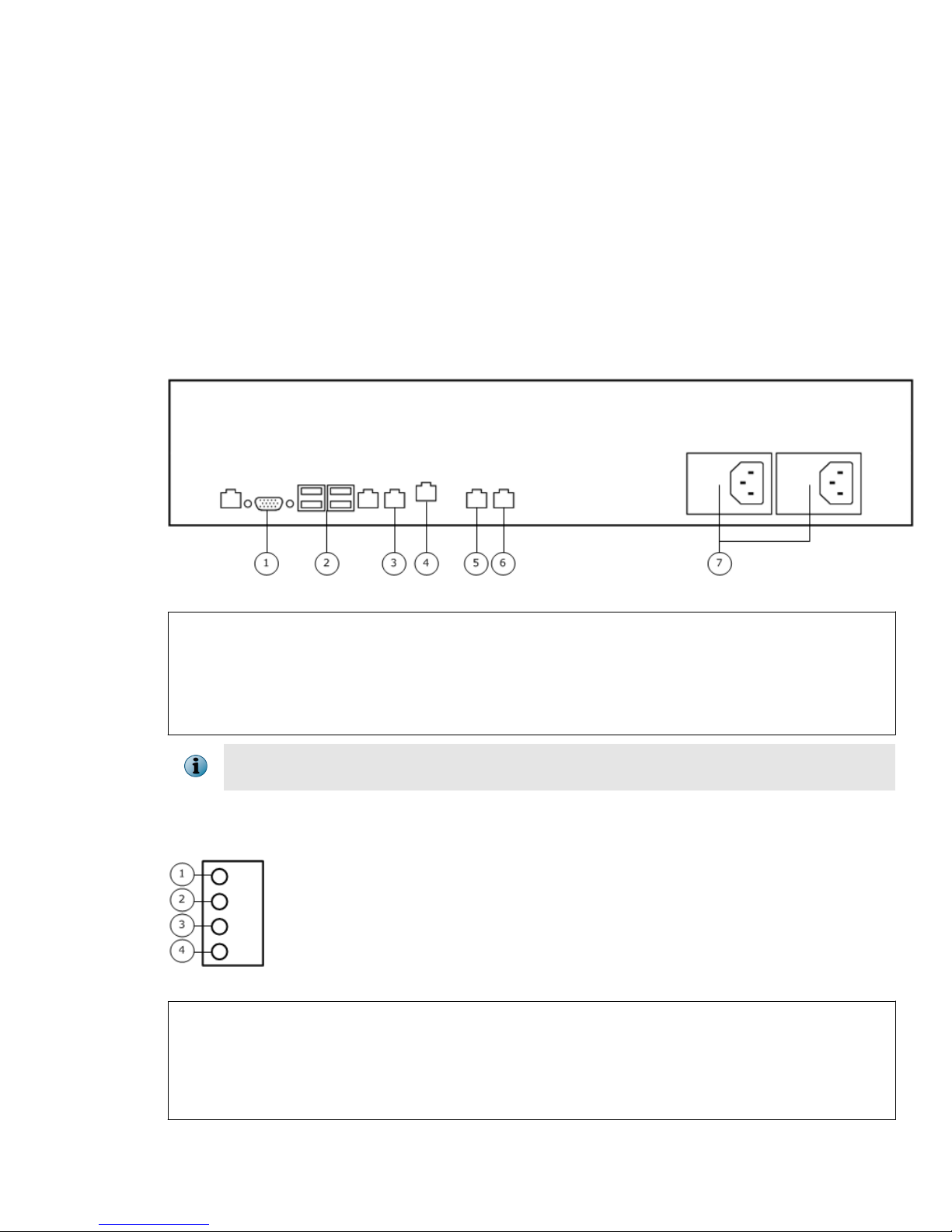
Back panel hardware components
The illustration identifies the hardware components on the back panel of the appliance.
Figure 7 5500 back panel
1
Capture port 1
2
Capture port 0
3
Power supplies
4
Management port
Front control panel
The control panel is on the front of the chassis.
5
VGA port
6
Serial port
7
USB ports
8
Remote access port (RMM)
Figure 8 5500 front control panel
1
Power button
2
System status
3
Hard drive activity
4
System ID button
5
System cold reset button
NICs 1, 3, and 4 are not used by the McAfee DLP appliance.
6
NIC 2 activity
7
NIC 4 activity
8
NIC 1 activity
9
NIC 3 activity
10
NMI button (recessed)
7
Page 8

Table 5 5500 system status indicator light states
Color State Status
Green Solid System booted and ready
Blink System degraded:
• Non-critical threshold crossed:
• Temperature
• Voltage
• Power supply input or output
• Fan redundancy lost, sufficient system cooling maintained
• Power supply redundancy lost
• Unable to use all of the installed memory — one or more DIMMS failed or disabled,
but functional memory remains available
• Correctable errors over a threshold and migrating to a spare DIMM (memory
sparing)
• Uncorrectable memory error in Mirroring Mode
• Correctable memory error threshold reached for failing DDR3 DIMM when the
system operates in RAS Mirroring Mode
• Battery failure
• Power unit sensor offset error asserted
• HDD HSC offline or degraded
• BMC executing uBoot
• BMC Watchdog has reset the BMC
8
Page 9

Table 5 5500 system status indicator light states (continued)
Color State Status
Amber Solid Fatal alarm — System has failed or shut down:
• CPU CATERR signal asserted
• CPU 1 missing
• CPU Thermal Trip
• CPU ERR2 signal asserted
• MSID mismatch detected
• DIMM failure when only one DIMM is present
• Runtime memory uncorrectable error in non-redundant mode
• DIMM Thermal Trip or equivalent
• SSB Thermal Trip or equivalent
• BMC/Video memory test failed
• Both uBoot BMC FW images are bad
• 240VA fault
• Power fault
• Fatal error in processor initialization:
• Processor families not identical • Processor cache sizes not identical
• Processor models not identical • Unable to synchronize processor
• Processor core/thread counts not
identical
Blink Non-fatal alarm — System is likely to fail:
• Critical threshold crossed:
• Temperature
• Voltage
• Power supply input or output
• VRD hot asserted
• Minimum number of fans to cool the system not present or failed
• Hard drive fault
• Insufficient power supplies present
• Correctable memory error threshold crossed for a failing DDR3 DIMM when the
system operates in a non-redundant mode
Off Off System powered off
frequency
• Unable to synchronize QPI link
frequency
9
Page 10

Power supply indicator lights
Each installed power supply module has a single indicator light to show the power supply status.
Table 6 5500 power supply indicator light states
Color State Status
Green Solid Output ON and OK
1 Hz Blink AC present / Only 12VSB on (power supply off) or power supply in cold redundant
state
2 Hz Blink Power supply FW updating
Amber Solid
Blink Power supply warning events where the power supply continues to operate:
• AC cord unplugged or AC power lost when a second parallel power supply still
has AC input power
• Power supply critical event causing a shutdown:
• Failure
• OCP
• OVP
• Fan failed
• High temperature
• High power
• High current
• Slow fan
Off Off No AC power to all power supplies
Replacing hardware components
McAfee DLP appliances ship with replaceable hard drives and power supplies.
Replace the hard drive
Each McAfee DLP appliance uses hot-swappable hard drives connected to a RAID controller. The RAID
controller allows the system to continue operating if a single disk drive fails. A single failed hard drive
can be replaced while the system is still operational.
Before you begin
The replacement hard drive must be the same capacity as the failed hard drive.
Task
1
Identify the failed hard drive.
A failed hard drive typically has an amber indicator light.
2
Remove the failed hard drive from the appliance.
a
Press the latch on the failed hard drive to release the spring-loaded handle.
b
Pull on the handle to remove the failed hard drive from the appliance.
10
Page 11

3
On the replacement hard drive, press the latch to release the spring-loaded handle.
4
Insert the replacement hard drive into the appliance.
a
Slide the drive into the empty hard drive bay until it is fully seated.
b
Press the handle until it latches.
c
If the appliance is turned off, turn it on.
After the drive is inserted, the RAID controller begins the rebuild operation.
Do not turn off the appliance until the rebuild operation is complete.
Performance is reduced while the rebuild operation takes place.
Replace the power supply
Each model has dual power supplies that allow the appliance to continue operating if one power supply
fails. The power supplies are hot-swappable, so a single power supply can be replaced while the
system is still operating.
Before you begin
Verify that the replacement power supply is compatible with your appliance model.
A power supply can be replaced while the appliance is turned on and running or when the appliance is
turned off.
Use both power supplies in normal operation so that two power supplies share the load.
Task
1
Disconnect the power cord from the failed power supply.
2
Unlatch the handle and remove the failed power supply.
3
Slide the replacement power supply into the appliance until it is fully seated and the latch has
engaged.
4
Connect the power cord to the replacement power supply.
Diagnosing hardware problems
McAfee DLP appliance shipments include the Intel Diagnostic Tool (IDT).
For information on performing hardware diagnostics using the supplied IDT, see KnowledgeBase article
PD24396.
11
Page 12

Re-imaging an appliance
Re-imaging an appliance restores the drives to their pre-installed state.
Re-imaging a model 1650 or 3650
Contact technical support for assistance on re-imaging a model 1650 or 3650.
Re-image a model 4400 or 5500 using the RMM
Use the RMM to re-image the appliance.
Before you begin
• Using an Ethernet cable, connect the RMM port to your network.
• Decide the IP address, subnet mask, and gateway IP address to use when configuring
the RMM port.
• Make sure Java is installed on the computer that connects to the RMM.
Task
1
Download the McAfee DLP Manager .iso image file to the computer that connects to the RMM.
a
Locate the grant number you received after purchasing the product.
b
In a web browser, go to www.mcafee.com/us/downloads.
c
Enter your grant number, then select the appropriate product and version.
d
In the Software Downloads tab, select and save the appropriate *.iso file.
2
Restart the appliance.
3
Press F2 before the operating system boots to enter the BIOS.
4
Select Server Management | BMC LAN Configuration.
5
Configure these items:
• Intel(R) RMM4 IPv4 LAN Configuration – IP Source — Enter the IP address, subnet mask, and gateway IP
address for the RMM port.
• User ID — Select root.
• User Status — Select Enabled.
• User name — Enter root.
• User password — Enter mcafee. You must enter this password twice.
6
Confirm the network and user information, and press F10 to save and exit the BIOS.
The appliance boots with the new settings.
7
On the computer that connects to the RMM, open a web browser and enter:
http://x.x.x.x
x.x.x.x is the IP address of the RMM port. The credentials are root/mcafee.
12
Page 13

8
Select the .iso file and re-image.
a
On the Remote Control tab, click Launch Console.
b
On the Device tab, select Redirect ISO and browse to the .iso file.
c
On the Remote Control tab, select Server Power Control | Power Cycle Server.
The appliance re-images using the .iso file.
d
Click Launch Console.
e
On the Device tab, disable Redirect ISO.
If you do not disable the Redirect ISO setting, the appliance will re-image after the next reboot,
removing your current installation and returning the appliance to factory default.
Re-image a model 4400 using the DVD
Use the DVD that shipped with the appliance to re-image a model 4400.
Task
1
Insert the DVD into the appliance.
2
Using a command line session, log on to the appliance as root.
3
Restart the system.
# reboot
The system restarts and re-images the drives.
4
After the restore completes, remove the DVD.
If you do not remove the DVD, the appliance will re-image from the DVD after the next reboot,
removing your current installation and returning the appliance to factory default.
Re-image a model 5500 using the USB drive
Use the USB drive included in the appliance shipment to re-image the appliance.
Task
1
Connect the USB drive to one of the USB ports on the appliance.
2
Restart the appliance.
3
Press F2 before the operating system boots to enter the BIOS.
4
Select Boot from USB device.
5
Press F10 to save and exit.
6
Follow the on-screen instructions to re-image from the USB drive.
7
After the re-image finishes, remove the USB drive.
If you do not remove the USB drive, the appliance will re-image from the USB drive after the next
reboot, removing your current installation and returning the appliance to factory default.
13
Page 14

Technical specifications
McAfee DLP appliances meet all safety and operational standards and are in compliance with FCC
standards.
McAfee DLP rack mounting requirements
McAfee DLP hardware must be rack mounted properly to ensure safe configuration.
This checklist provides requirements for installing McAfee DLP hardware in a rack.
• Elevated operating ambient temperature — If installed in a closed or multi-unit rack assembly,
the operating ambient temperature of the rack environment might be greater than room ambient.
Consider installing the equipment in an environment compatible with the maximum ambient
temperature (MAT) specified by the manufacturer.
• Reduced air flow — When installing the equipment in a rack, do not compromise the amount of
air flow required for safe operation.
• Mechanical loading — When mounting the equipment, make sure no hazardous conditions are
created due to uneven mechanical loading.
• Circuit overloading — When connecting the equipment to the supply circuit, consider the effect
that circuit overloading might have on overcurrent protection and supply wiring. Use appropriate
consideration of equipment nameplate ratings when addressing this concern.
• Reliable earthing — Maintain reliable earthing of rack-mounted equipment. Give particular
attention to supply connections that are not directly connected to the branch circuit, such as power
strips.
McAfee DLP power redundancy
McAfee DLP appliances with more than one power supply must be configured to provide redundancy
by sharing the load while operating at nominal power. Additional protection is provided if two electrical
outlets that are on different circuit breakers are used.
If one power supply fails, a backup fan automatically turns on, an alarm sounds, and a warning LED
illuminates. If a power supply fails, contact McAfee for a replacement unit.
If a McAfee DLP appliance loses power for any reason, the appliance will not come back up unless you
change the BIOS setting in advance. The motherboard is set to off by default.
McAfee DLP FCC compliance
McAfee DLP hardware has been tested and found to comply with the limits for a Class A digital device,
pursuant to Part 16 of the Federal Communications Commission rules. Any modifications to McAfee
DLP equipment, unless expressly approved by the party responsible for compliance, could void
authority to operate the equipment.
Operation of the McAfee DLP appliances is subject to the following conditions:
• The device might cause harmful interference, and
• The device must accept any interference received, including interference that might cause
unwanted operation.
These limits are designed to provide reasonable protection against harmful interference when the
equipment is operated in a commercial environment.
14
Page 15

McAfee DLP equipment generates, uses, and can radiate radio frequency energy. If not installed and
used in accordance with the instruction manual, it might cause harmful interference to radio
communications. If operation of this equipment in a residential area causes harmful interference, it
must be corrected at owner expense.
McAfee DLP safety compliance guidelines
McAfee DLP appliances must be operated in compliance within strict safety guidelines.
McAfee DLP hardware must be installed only in Restricted Access locations, such as dedicated
equipment rooms or electrical closets.
Disconnect all power supply cords before servicing. There is a RISK OF EXPLOSION if a battery is
replaced by an incorrect type. Dispose of used batteries according to industry standards.
Copyright © 2015 McAfee, Inc. www.intelsecurity.com
Intel and the Intel logo are trademarks/registered trademarks of Intel Corporation. McAfee and the McAfee logo are trademarks/
registered trademarks of McAfee, Inc. Other names and brands may be claimed as the property of others.
B00
15
 Loading...