

Page 1

WebDAQ 316
User's Guide
July 2017. Rev 1
Internet Enabled Thermocouple Data Logger
© Measurement Computing Corporation
Page 2

HM WebDAQ 316
Trademark and Copyright Information
Measurement Computing Corporation, InstaCal, Universal Library, and the Measurement Computing logo are
either trademarks or registered trademarks of Measurement Computing Corporation. Refer to the Copyrights &
Trademarks section on mccdaq.com/legal
for more information about Measurement Computing trademarks.
Other product and company names mentioned herein are trademarks or trade names of their respective
companies.
© 2017 Measurement Computing Corporation. All rights reserved. No part of this publication may be
reproduced, stored in a retrieval system, or transmitted, in any form by any means, electronic, mechanical, by
photocopying, recording, or otherwise without the prior written permission of Measurement Computing
Corporation.
Notice
Measurement Computing Corporation does not authorize any Measurement Computing Corporation product for
use in life support systems and/or devices without prior written consent from Measurement Computing
Corporation. Life support devices/systems are devices or systems that, a) are intended for surgical implantation
into the body, or b) support or sustain life and whose failure to perform can be reasonably expected to result in
injury. Measurement Computing Corporation products are not designed with the components required, and are
not subject to the testing required to ensure a level of reliability suitable for the treatment and diagnosis of
people.
2
Page 3

Table of Contents
Preface
About this User's Guide ....................................................................................................................... 5
What you will learn from this user's guide ......................................................................................................... 5
Conventions in this user's guide ......................................................................................................................... 5
Where to find more information ......................................................................................................................... 5
Hazardous voltages ............................................................................................................................................. 5
Hazardous locations .......................................................................................................................................................... 5
Chapter 1
Introducing the WebDAQ 316 .............................................................................................................. 6
Powered by Raspberry Pi®.................................................................................................................................. 6
Integrated operating system and web service ..................................................................................................... 6
Ethernet interface ................................................................................................................................................ 6
Functional block diagram ................................................................................................................................... 7
Unpacking........................................................................................................................................................... 7
Chapter 2
Setting up the WebDAQ 316................................................................................................................. 8
Connecting to a local area network..................................................................................................................... 8
Connecting to a network with DHCP enabled .................................................................................................................. 8
Connecting directly to a PC .............................................................................................................................................. 8
Connecting the external power adapter .............................................................................................................. 8
Detecting the device on the network ................................................................................................................... 8
Accessing the WebDAQ web interface ............................................................................................................................. 9
Configuring the network router for communication across networks ................................................................ 9
Security ............................................................................................................................................................. 10
Restoring factory default settings ..................................................................................................................... 10
Chapter 3
Functional Details ............................................................................................................................... 11
Front panel components .................................................................................................................................... 11
Screw terminal .................................................................................................................................................................11
Spring terminal ................................................................................................................................................................12
Rear panel components ..................................................................................................................................... 13
External power connector ................................................................................................................................................13
Power button ....................................................................................................................................................................13
Function button ................................................................................................................................................................13
LED status indicators .......................................................................................................................................................14
SD card slot......................................................................................................................................................................14
Factory reset button .........................................................................................................................................................14
Ethernet connector ...........................................................................................................................................................14
Ground connector ............................................................................................................................................................15
USB connectors ...............................................................................................................................................................15
Analog input circuitry ....................................................................................................................................... 15
Open thermocouple detection ..........................................................................................................................................15
Input Impedance ..............................................................................................................................................................15
Overvoltage protection.....................................................................................................................................................15
Thermocouple measurement accuracy .............................................................................................................................15
Replacing the battery ........................................................................................................................................ 16
Updating WebDAQ firmware ........................................................................................................................... 16
Recovering from a failed update ......................................................................................................................................17
Calibrating the hardware................................................................................................................................... 17
3
Page 4

WebDAQ 316 User's Guide
Chapter 4
Specifications ...................................................................................................................................... 18
Thermocouple input .......................................................................................................................................... 18
Temperature measurement accuracy ................................................................................................................ 19
Digital input/output........................................................................................................................................... 21
Network ............................................................................................................................................................ 22
Ethernet connection .........................................................................................................................................................22
Network interface ............................................................................................................................................................22
Network factory default settings ......................................................................................................................................22
Processor / Memory .......................................................................................................................................... 22
USB ports ......................................................................................................................................................... 23
SD memory card slot ........................................................................................................................................ 23
LED indicators .................................................................................................................................................. 23
Push buttons ...................................................................................................................................................... 24
Ground connector ............................................................................................................................................. 24
Power ................................................................................................................................................................ 24
Mechanical ....................................................................................................................................................... 25
Environmental .................................................................................................................................................. 25
Safety voltages .................................................................................................................................................. 25
Signal connectors .............................................................................................................................................. 25
Screw terminal .................................................................................................................................................................26
Spring terminal ................................................................................................................................................................26
EU Declaration of Conformity ............................................................................................................ 27
4
Page 5
Preface
About this User's Guide
What you will learn from this user's guide
This user's guide describes the Measurement Computing WebDAQ 316 data acquisition device, the WebDAQ
web interface, and lists device specifications.
Conventions in this user's guide
For more information
Text presented in a box signifies additional information related to the subject matter.
Caution! Shaded caution statements present information to help you avoid injuring yourself and others,
damaging your hardware, or losing your data.
bold text Bold text is used for the names of objects on a screen, such as buttons, text boxes, and check boxes.
italic text Italic text is used for the names of manuals and help topic titles, and to emphasize a word or phrase.
Where to find more information
Additional information about WebDAQ 316 hardware is available on our website at www.mccdaq.com. You
can also contact Measurement Computing Corporation with specific questions.
WebDAQ web interface: Open the Help page for information about using WebDAQ software; see page 9.
Knowledgebase: kb.mccdaq.com
Tech support form: www.mccdaq.com/support/support_form.aspx
Email: techsupport@mccdaq.com
Phone: 508-946-5100 and follow the instructions for reaching Tech Support
For international customers, contact your local distributor. Refer to the International Distributors section on our
website at www.mccdaq.com/International
.
Hazardous voltages
Take the following precautions if you connect hazardous voltages to the WebDAQ 316 spring
terminals. A hazardous voltage is a voltage greater than 42.4 V
Caution! Ensure that hazardous voltage wiring is performed only by qualified personnel adhering to local
electrical standards.
Do not mix hazardous voltage circuits and human-accessible circuits on the same device.
Make sure that devices and circuits connected to the WebDAQ 316 are properly insulated from
human contact.
Hazardous locations
or 60 VDC to earth ground.
pk
The WebDAQ 316 is not certified for use in hazardous locations.
5
Page 6

Chapter 1
Introducing the WebDAQ 316
The WebDAQ 316 is part of the WebDAQ Series of Internet enabled data loggers. WebDAQ 316 is a
thermocouple acquisition and logging device that provides the following features:
16 differential thermocouple inputs
75 S/s aggregate sample rate
250 Vrms channel-to-earth isolation
Overvoltage protection between any two inputs
50/60 Hz noise rejection
Cold junction compensation (CJC)
Auto zero channel
Four bidirectional, isolated DIO
10/100 Ethernet interface
Support for USB mass storage devices and SD cards for data logging or file transfer
Powered by a +9 VDC external supply (included)
WebDAQ Series devices are designed with an integrated operating system and web interface. You
communicate with the device over a network connection using the web interface opened in a web browser.
Mobile support – access the WebDAQ 316 from any device with a web browser, such as a phone or tablet
Remote monitoring and control
Run simple to complex logging operations
Flexible task scheduling
Powered by Raspberry Pi®
The WebDAQ 316 is designed with the Raspberry Pi Compute Module, featuring a quad core processor with
speeds up to 1.2 GHz, 1GB RAM and 4 GB Flash memory.
Integrated operating system and web service
The WebDAQ 316 is a complete data acquisition system containing an embedded operating system and web
server. The operating system resides in internal flash memory, and includes a web service and device driver. All
configuration, acquisition, and data management is performed using the web interface.
Ethernet interface
The WebDAQ 316 has a built-in 10/100 BASE-T auto-negotiation, high-speed communication port. You can
access and configure your WebDAQ 316 from anywhere with access to the network to which it is connected.
A unique MAC address is assigned to each device at the factory. You configure the Ethernet connection settings
through a web interface. The default network name uses the format
lower six digits of the factory-assigned MAC address. You can change this name with the web interface.
webdaq-xxxxxx, where xxxxxx are the
6
Page 7
WebDAQ 316 User's Guide Introducing the WebDAQ 316
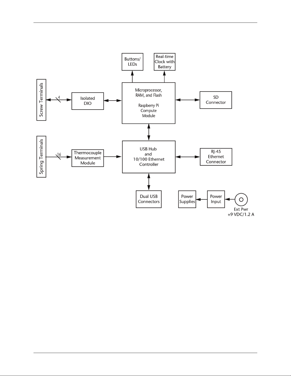
Functional block diagram
Device functions are illustrated in the block diagram shown here.
Figure 1. WebDAQ 316 functional block diagram
Unpacking
As with any electronic device, you should take care while handling to avoid damage from static
electricity. Before removing the board from its packaging, ground yourself using a wrist strap or by simply
touching the computer chassis or other grounded object to eliminate any stored static charge.
7
Page 8

Chapter 2
Setting up the WebDAQ 316
Connecting to a local area network
The WebDAQ 316 requires a TCP/IP connection to a network or the Ethernet port of a computer. A standard
Ethernet cable is shipped with the device.
The WebDAQ 316 IP address type is set by default for DHCP/Link-Local. When connected to a network, the
device first attempts to receive an IP address from a DHCP server. If this fails, a link-local address is used. Use
of a static address requires configuration via the web interface. The IP address identifies the WebDAQ 316 on
the network, and is used to access the web interface.
Connecting to a network with DHCP enabled
Connect one end of the Ethernet cable to the connector on the WebDAQ 316 rear panel, and connect the other
end to a 10Base-T or 100Base-TX compatible Ethernet port, hub, or switch.
Once the device is detected, DHCP assigns an address. A different address may be assigned each time the
hardware is connected to the network.
Connecting directly to a PC
Connect one end of the Ethernet cable to the connector on the WebDAQ 316 rear panel, and connect the other
end directly to the Ethernet port on a PC. The WebDAQ 316 attempts to communicate with the host PC using
169.254.100.100 – the link-local address stored on the device. The host PC may accept this address or use a
different address. The link-local address is valid only for communications between the WebDAQ 316 and the
host PC to which it is connected.
Connecting the external power adapter
Connect the network cable before connecting to external power
Connecting to the external supply before installing on a network results in the device attempting to autonegotiate a network address before one is available.
WebDAQ 316 ships with a 9 volt, 1.67 amp external power adapter included with the shipment (MCC p/n
PS-9V1AEPS230V).
Connect the adapter cord to the power connector labeled
AC adapter into an electrical outlet.
POWER LED on the rear panel turns yellow as the hardware starts up, and then green to indicate it is ready
The
for use. Refer to Figure 7 on page 13 for the location of this LED.
EXT PWR on the device rear panel, and plug the
Detecting the device on the network
WebDAQ uses the "zeroconf" zero-configuration protocol to announce its presence on a local area network.
Zeroconf uses a device name which can be accessed from other computers on the network.
Zero-configuration networking is helpful to find your WebDAQ hardware on the network
The easiest way to add zeroconf support to Windows is to install Bonjour Print Services. Bonjour software is
Apple's implementation of zero-configuration networking, and is readily available as a free download – open a
browser window and search for Bonjour Print Services.
Zeroconf is built into popular applications such as Apple ITunes® and instant messaging software, so your
computer may already support it.
Many Linux systems will have the avahi version of zeroconf installed by default, so it’s likely zeroconf is
available if you’re running Linux.
8
Page 9
WebDAQ 316 User's Guide Setting up the WebDAQ 316
Accessing the WebDAQ web interface
To access the WebDAQ web interface, open a browser* window and enter http://webdaq-xxxxxx.local, where
xxxxxx is the last 6 digits of the MAC address. The MAC address is on a label at the bottom of the WebDAQ
enclosure.
If your network supports zeroconf protocol, the WebDAQ web interface opens.
If the web interface does not open or an error is returned, install a device discovery tool such as Bonjour
Print Services. Refer to the note about zero-configuration networking on page 8.
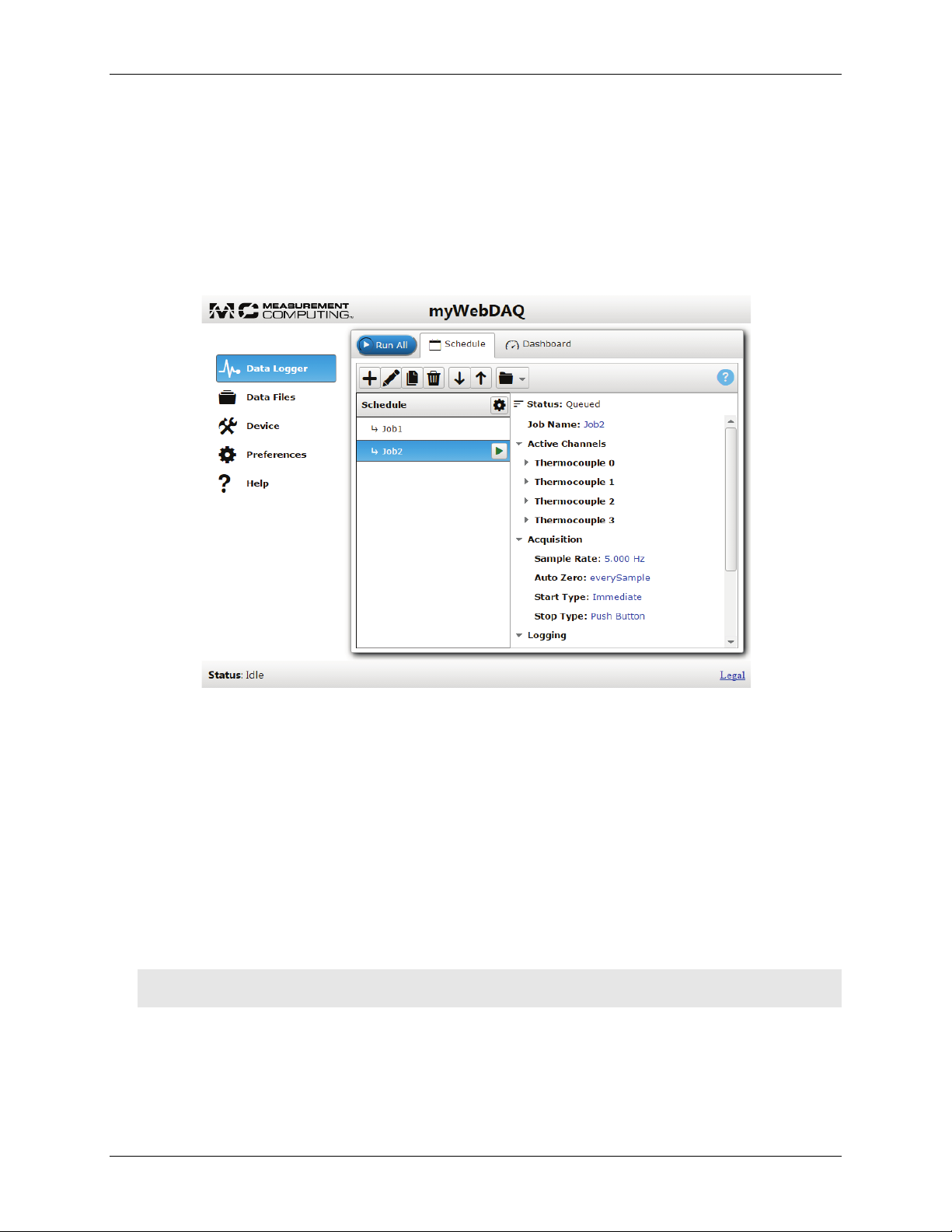
The WebDAQ web interface is shown in Figure 2.
Figure 2. WebDAQ 316WebDAQ web interface
Use the WebDAQ web interface to configure hardware and acquisition options, schedule and run jobs, and to
view and manage data. The Help window provides details about all components on the web interface.
Once a connection is established and you can communicate to the device, you can change the configuration for
other network scenarios.
* The latest version of Chrome, Firefox, Safari, UC Browser, or Opera recommended. Compatible with IE v11
with the latest Windows Updates installed. Not recommended for use with other IE versions or the Edge
browser.
Configuring the network router for communication across networks
To communicate with the WebDAQ 316 over the internet from a computer connected to a different network,
you must change the network configuration of the network router.
Caution! This procedure should only be performed by a network administrator or computer professional.
Incorrect settings can significantly disrupt a network.
In the following procedure, the WebDAQ 316 is installed on the host LAN, the computer is installed on the
client LAN, and it is assumed that you have successfully connected the device to a local network.
1. Determine the IP address of the WebDAQ 316 – open the Device window from the web interface, and note
the IP Address value in the Network Settings tab.
2. Configure your router so that the address determined above is a static address. The procedure for
accomplishing this varies between routers; refer to your router documentation for instructions.
9
Page 10

WebDAQ 316 User's Guide Setting up the WebDAQ 316
IP address
192.168.0.101
Gateway
192.168.0.1
DHCP setting
DHCP + link-local enabled
Security level
Off
User name
admin (case-sensitive)
3. Configure the firewall/router to forward an unused port to port 80 on the WebDAQ 316 at the IP address
configured for the device.
Note the static IP address assigned to the router – this is referred to as the WAN address.
4. To access your WebDAQ from a remote location, enter the WAN address followed by the port selected
above preceded by a colon in the web browser.
The format of the address entered in the browser is: 000.000.000.000:00000 (WAN address of router:port
selected for the WebDAQ).
Security
Use the web interface to set the level of access to the website and to change the administrator password.
High: access to the web page requires a password.
Medium: access to the web page is permitted for any user, and data can be read by any user, but changes to
the device configuration or files require a password.
Off: full access is permitted for all users; no password is required.
By default, security access is set to "Off", and the administrator password is set to "admin".
To change the security level or password, open the web interface and go to the Device window, Security tab.
Use the device Reset button to restore security settings to factory default values.
Restoring factory default settings
To restore network configuration and security settings to the factory default values, use a paper clip to press the
CONFIG RESET button. When pressed, the default network and security settings are written to the device and
the WebDAQ 316 is rebooted.
Factory default
Parameter Specification
subnet mask 255.255.255.0
Password admin (case-sensitive; editable)
You can change the network settings, security level, and password with the web interface. The user name
"admin" cannot be changed.
10
Page 11

1
Screw terminal
2
Spring terminal
Functional Details
Front panel components
Front panel components are shown in Figure 3.
Detachable screw terminal
Detachable spring terminal
Chapter 3
Figure 3. Front panel
Screw terminal
Connect up to four digital I/O lines (DIO0 to DI03) to the detachable screw terminal. Refer to Figure 4 for signal
locations.
Figure 4. Screw terminal pinout
The digital ground (GND) terminals provide a common ground for the digital bits.
Digital connections
The digital I/O lines are electrically isolated from the thermocouple circuits. Each bit is individually
configurable for input or output, and features Schmitt trigger inputs and open drain outputs. All DIO channels
are pulled high to 5 V.
Any digital bit can be configured with the web interface as a trigger to start or stop an acquisition. Any digital
bit can also be configured to trigger an alarm, and be driven high or low when an alarm occurs.
11
Page 12
WebDAQ 316 User's Guide Functional Details
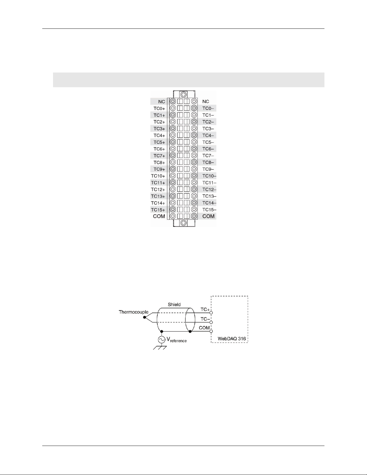
Spring terminal
Connect up to 16 thermocouples (TC0+/TC0– to TC15+/TC15–) and two common reference connections (COM)
to the 36-position detachable spring terminal. Refer to Figure 5 for signal locations.
Caution! MCC strongly recommends that you ground yourself using a wrist strap before handling the
thermocouple sensors.
Figure 5. Spring terminal pinout
The common terminals (COM) provide a common reference for the thermocouple inputs.
Thermocouple connections
A thermocouple consists of two dissimilar metals that are joined together at one end. When the junction of the
metals is heated or cooled, a voltage is produced that correlates to temperature.
The WebDAQ 316 supports type J, K, S, R, B, E, T, N thermocouples (TC), and provides overvoltage
protection between any two inputs. A typical thermocouple connection is shown in Figure 6.
Figure 6. Typical thermocouple connection
Connect the shield to a common mode voltage reference on the thermocouple. A valid reference is voltage
within ±1.2 V of all the connected thermocouples.
Minimizing thermal gradients
Changes in the ambient air temperature near the thermocouple connectors or a thermocouple wire conducting
heat directly to terminal junctions can cause thermal gradients. Observe the following guidelines to minimize
thermal gradients and improve system accuracy:
Use small-gauge thermocouple wire. Smaller wire transfers less heat to or from the terminal junction.
Run thermocouple wiring together near the spring terminal connector to maintain a consistent temperature.
Avoid running thermocouple wires near hot or cold objects.
12
Page 13
WebDAQ 316 User's Guide Functional Details
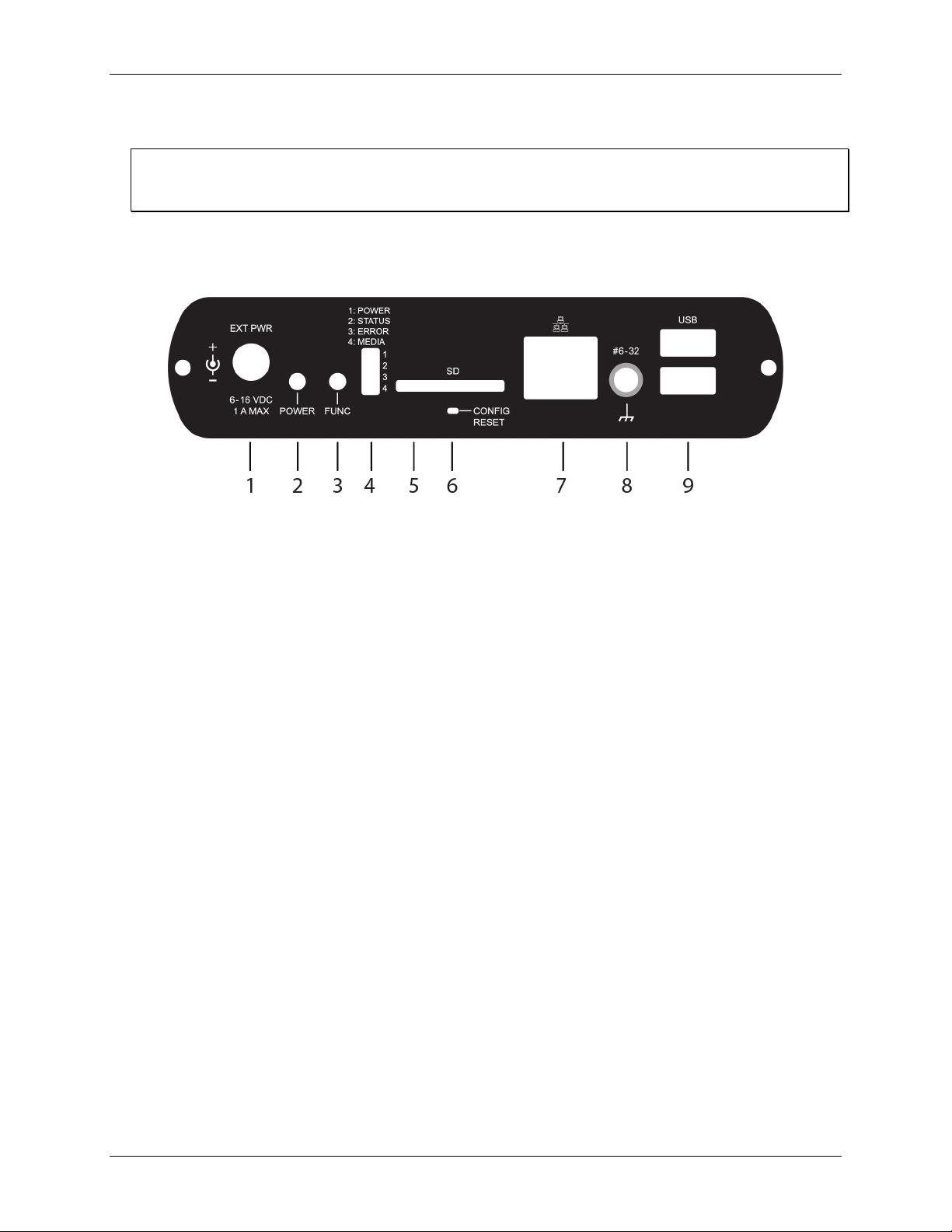
1
External power connector
4
LED status indicators (4)
7
Ethernet connector
3
Function button
6
Factory reset button
9
USB connectors
Minimize adjacent heat sources and air flow across the terminals.
Keep the ambient temperature as stable as possible.
Increasing the thermocouple length
If you need to increase the length of your thermocouple, use the same type of TC wires to minimize the error
introduced by thermal EMFs.
Rear panel components
Rear panel components are shown in Figure 7.
Figure 7. Rear panel
2 Power button 5 SD card slot 8 Ground connector
External power connector
Connect the external AC adapter that shipped with the device to the connector labeled EXT PWR on the rear
panel. The power supply provides 9 VDC, 1.2 A power to the WebDAQ 316.
If using a different power supply than what was shipped with the hardware, ensure that the supply has a positive
center pin.
Power button
The button labeled POWER turns the WebDAQ device on and off.
Press briefly to turn the device on.
Press for approximately 1 second to begin shutting down the operating system and WebDAQ hardware;
release the button when the
POWER LED blinks yellow. The operating system automatically powers off
the WebDAQ device at the end of the shutdown procedure.
If the WebDAQ device stops responding for any reason, you may press the power button and hold it for
approximately 4 seconds to force the device to power off. Any unsaved changes may be lost when
powering down using this method.
Function button
The button labeled FUNC has two functions; it can be used to eject external media or to start/stop an acquisition.
Eject external media (default): Pressing the button unmounts all removable media so they can be safely
removed from the device.
Start or stop an acquisition (requires configuration with the web interface): When configured, pressing
this button starts an acquisition, or stops an acquisition that is currently running.
Use the web interface to safely unmount removable media, when present.
When removable media is plugged into the WebDAQ 316, the operating system opens it for writing. To safely
remove the media, you must unmount it first.
13
Page 14

WebDAQ 316 User's Guide Functional Details
1: POWER
Steady yellow
Device is booting up
Steady green
Device boot is successful
Blinking yellow
Device is shutting down
Off
Device is off
2: STATUS
Blinking yellow
Device is configuring hardware
Steady green
Hardware configuration is complete
Flashing green
Waiting for a scheduled start condition to be met
Blinking heartbeat
Scheduled start condition is met; waiting for job start condition to be met.
Blinking green
Data is being acquired (job start condition is met)
Off
No error detected.
3: ERROR
Blinking yellow
Error condition is detected. This LED blinks even when the software is
Off
No error detected
4: MEDIA
Blinking yellow
A job is configured to log to external media, but the job hasn't started yet;
Steady yellow
External media is inserted into the SD card slot or USB storage port
Blinking green
Currently logging to an external SD card or USB storage device
Steady green
Media has been made safe for removal using the function button, but has not
When a job is configured to log data to external media, pressing FUNC while the job is running will not eject
the media.
MEDIA LED is steady green when all media is unmounted and safe to remove, and off when all media is
The
removed.
LED status indicators
The WebDAQ 316 has four LEDs on the rear panel that indicate the status of power and host communications.
The following table defines the LED states during normal operation.
LED states – normal operating mode
Label State Description
100 ms on/2s off)
configured to ignore the error
Error state is cleared when the next schedule starts.
pushbutton will not let you eject media
been removed
WebDAQ LEDs behave differently when software is updated on the device. For information about LED states
during software update mode, refer to Updating WebDAQ firmware on page 16.
SD card slot
The SD slot accepts SD (Secure Digital), SDHC, SDXC, MMC, and TransFlash memory cards. Memory cards
can be ejected using the web interface or the hardware
FUNC button, unless the button is configured to
start/stop an acquisition.
When removable media is plugged into the WebDAQ 316, the operating system opens it for writing. Use the
FUNC button (page 13) or web interface to unmount the SD card before removing.
Factory reset button
The recessed button labeled CONFIG RESET restores network and alarm settings to factory default values.
When pressed, the default settings are written to the device and the WebDAQ 316 is rebooted. Refer to page 10
for a list of the default settings that are restored.
Ethernet connector
The WebDAQ 316 has one 10 Base-T/100 Base-TX, auto-negotiation, high-speed communication port. The
port connector is an RJ-45, eight-position connector. The Ethernet port accepts shielded or unshielded twisted
pair cable. The maximum communication distance without using a repeater is 100 m (328 ft).
14
Page 15

WebDAQ 316 User's Guide Functional Details
Ground connector
Measurement Computing recommends grounding the WebDAQ device by connecting a #6-32 ground screw to
the connector labeled
#6-32.
USB connectors
The two high-speed USB ports can be used for connections to a mass storage device.
When removable media is plugged into the WebDAQ 316, the operating system opens it for writing. Use the
FUNC button (page 13) or web interface to unmount the USB device before removing.
Use a self-powered hub when external media requires high current
USB-powered hard drives may use an excessive amount of current during operation. The WebDAQ device
could shut down or experience other errors if the power requirements of a connected device exceed the power
available. Use a self-powered hub if the current requirement of external media exceeds 500 mA.
We recommend that you connect USB-powered hard drives before powering up the WebDAQ 316.
Analog input circuitry
Each channel passes through a differential filter and then is multiplexed and sampled by a 24-bit ADC. The
channels share a common ground (COM) that is isolated from the digital subsystem.
The circuitry for one thermocouple channel is shown in Figure 8.
Figure 8. Input circuitry of one TC channel
Open thermocouple detection
Each channel has an open thermocouple detection (OTD) circuit which consists of a current source between the
TC+ and TC– terminals. If an open thermocouple is connected to the channel, the current source forces a fullscale negative voltage across the terminals.
Input Impedance
Each channel has a resistor that produces an input impedance between the TC and COM terminals. The gain
and offset errors resulting from the source impedance of connected thermocouples are negligible for most
applications. Thermocouples with a longer lead length can introduce more significant errors.
Overvoltage protection
WebDAQ 316 provides 30 V overvoltage protection between any two inputs.
Thermocouple measurement accuracy
Thermocouple measurement errors depend partly on the type and accuracy of the thermocouple, the temperature
being measured, the resistance of the thermocouple wires, and the cold-junction temperature.
For increased accuracy, follow the guidelines listed on page 12 to minimize thermal gradients, and use the auto
zero channel to compensate for offset errors.
15
Page 16

WebDAQ 316 User's Guide Functional Details
Cold-junction accuracy
Heat dissipated by nearby heat sources can cause errors in thermocouple measurements by heating the
WebDAQ 316 terminals to a different temperature than the cold-junction compensation sensor. Thermal
gradient across the terminals can cause the terminals of different thermocouple channels to be at different
temperatures, which creates accuracy errors and affects the relative accuracy between channels.
The temperature measurement accuracy specifications include errors caused by the thermal gradient across the
WebDAQ 316 terminals for configurations with the terminals facing forward or upward.
Auto zero channel
The WebDAQ 316 has an internal auto zero channel which can be subtracted from each thermocouple reading
to compensate for offset errors. Use the web interface to enable auto zero. WebDAQ 316 specifications assume
that auto zero is enabled and applied to every sample.
Replacing the battery
A button cell lithium battery provides the time reference for WebDAQ hardware when the device is powered
off. The average lifespan of the battery is approximately 10 years.
Caution! The discharge of static electricity can damage some electronic components. Before removing the
WebDAQ 316 from its housing, ground yourself using a wrist strap or touch the computer chassis
or other grounded object to eliminate any stored static charge.
Perform the following procedure to replace the battery.
1. Power down the WebDAQ 316 and disconnect the power supply.
2. Remove the spring terminal and screw terminal from the front panel.
3. On the rear panel, remove the Ethernet cable, and any removable media.
4. Remove the two rear panel screws and bezel.
5. Slide out the circuit board.
6. Remove the battery by sliding it forward toward the slot, and replace with a 3 V button cell battery – type
BR1225, CR1225 or similar.
7. Slide the circuit board back into the enclosure.
8. Attach the rear bezel and rear faceplate, and secure with the two screws removed in step 4.
9. Connect the spring and screw terminal headers to the front panel.
Set the device system clock from the Device window, Device Info tab on the web interface.
Updating WebDAQ firmware
Device firmware is bundled with the operating system and web server in a software update (*.swu) file.
Firmware updates are posted on the Measurement Computing Firmware Updates page and are available for
download. Use the web interface to install the *.swu file.
Perform the following procedure to update device firmware.
1. Download WebDAQ 316 firmware from the Measurement Computing Firmware Updates
directory on a USB mass storage device or SD card.
2. Connect the external media to the WebDAQ 316 device.
3. Open a browser window enter
address.
4. Open the
All device LEDs turn yellow as the update begins. The software waits 10 seconds to search for the update
file to allow for slower devices to enumerate, or to insert removable media containing the update file.
Device window, Device Info tab, and click the Update button on the Firmware panel.
http://webdaq-xxxxxx.local, where xxxxxx is the last 6 digits of the MAC
page to the root
16
Page 17

WebDAQ 316 User's Guide Functional Details
All LEDs
Solid yellow
Software update is starting
POWER
Blinking yellow
Software update is running
STATUS
Blinking green
Update file is located; device is being updated
Blinking yellow
Update file cannot be located; insert media with update file
ERROR
Blinking green
Update is successful; device will reboot in approximately 5 seconds
Blinking yellow
Update failed; user must retry
The STATUS LED blinks yellow if the software cannot locate the update file; if this occurs, verify that the
*.swu file is present and in the root of the media.
5. The
6. The
STATUS LED blinks green when the update file is detected.
The
POWER LED blinks yellow as the update file is installed.
ERROR LED blinks green when the software update is complete, and the device reboots in
approximately 5 seconds.
ERROR LED blinks yellow if the update is not successful. If this occurs, verify that the *.swu file is
The
available, and repeat the procedure.
The table below summarizes the LED behavior during a software update.
LED states – software update mode
LED State Description
Recovering from a failed update
If the update process is not successful, perform the following procedure to update the software image:
1. Press the
Power button to power down the WebDAQ 316. If the device is not responsive, press the Power
button for 4 seconds to force the device to power off. Power down the device; unsaved changes may be
lost.
2. Press the
FUNC button and POWER button at the same time to power on the WebDAQ 316 and update the
software image. Refer to page 13 for more information about these buttons.
Updating the software using this method is the same as initiating a firmware update using the web
interface.
Calibrating the hardware
The Measurement Computing Manufacturing Test department performs the initial factory calibration. Return
the device to Measurement Computing Corporation when calibration is required. The recommended calibration
interval is one year.
17
Page 18

16 thermocouple channels
1 internal cold-junction compensation channel
ADC resolution
24 bits
Type of ADC
Delta-Sigma
Sampling mode
Scanned
Voltage measurement range
±78.125 mV
Temperature measurement
ranges
Works over temperature ranges defined by NIST
(J, K, T, E, N, B, R, S thermocouple types)
Sample Rate (all channels): 1 S/s
High-speed mode:
Common-mode voltage
range
Channel-to-COM: ±1.2 V min
COM-to-earth ground: ±250 V
High-resolution mode at DC
and 50 to 60 Hz
Channel-to-COM: 100 dB
COM-to-earth ground: >170 dB
Channel-to-COM: 70 dB
High-resolution mode
14.4 Hz
High-speed mode
78 Hz
High-resolution noise
Overvoltage protection
±30 V between any two inputs
impedance
Input current
50 nA
High-resolution mode
200 nVrms
High-speed mode
7 µVrms
0.03% typ at 25 °C
0.15% max at 0 °C to 60 °C
0.16% max at 0 °C to 60 °C
High-resolution mode
4 µV typ, 6 µV max
High-speed mode
14 µV typ, 17 µV max
Offset error from source
Add 0.05 µV per Ω, when source impedance
Specifications
All specifications are subject to change without notice.
Typical for 0 °C to 50 °C unless otherwise specified.
Thermocouple input
Table 1. Thermocouple input specifications
Parameter Condition Specification
Chapter 4
Number of channels
Timing mode
Common-mode rejection
ratio (CMMR)
Input bandwidth
Automatically set for either highresolution or high-speed mode based
on the requested scan rate,
regardless of the number of
channels.
High-speed mode at 0 to 60 Hz
1 internal auto zero channel
High resolution mode:
Requested scan rate: ≤1 Hz
Conversion Time (per channel): 55 ms
Requested scan rate: >1 Hz
Conversion Time (per channel): 740 µs
Sample Rate
COM-to-earth ground: >150 dB
(all channels): 75 S/s
rejection
Differential input
Input noise
Gain error
Offset error
impedance
50 Hz and 60 Hz 60 dB
78 MΩ
High-resolution mode
High-speed mode
0 °C to 60 °C
0.07% typ at 0 °C to 60 °C
0.04% typ at 25 °C
0.08% typ at 0 °C to 60 °C
>50 Ω
18
Page 19
WebDAQ 316 User's Guide Specifications
Cold-junction compensation
accuracy
The device is lying flat or facing
temperature.
Measurement sensitivity
High-resolution mode
Type J, K, T, E, N: <0.02 °C
High-speed mode
Type J, K, T, E: <0.25 °C
Type R, S: <2.8 °C
Parameter Condition Specification
0.8 °C typ, 1.7 °C max
Warm-up time
upward and is in a constant ambient
15 minutes recommended
Temperature measurement accuracy
Measurement sensitivity represents the smallest change in temperature that a sensor can detect. It is a function
of noise. The values assume the full measurement range of the standard thermocouple sensor per
ASTM E230-87.
Table 2. Temperature accuracy specifications
Parameter Condition Specification
Type B, R, S: <0.15 °C
Type N: <0.35 °C
Type B: <1.2 °C
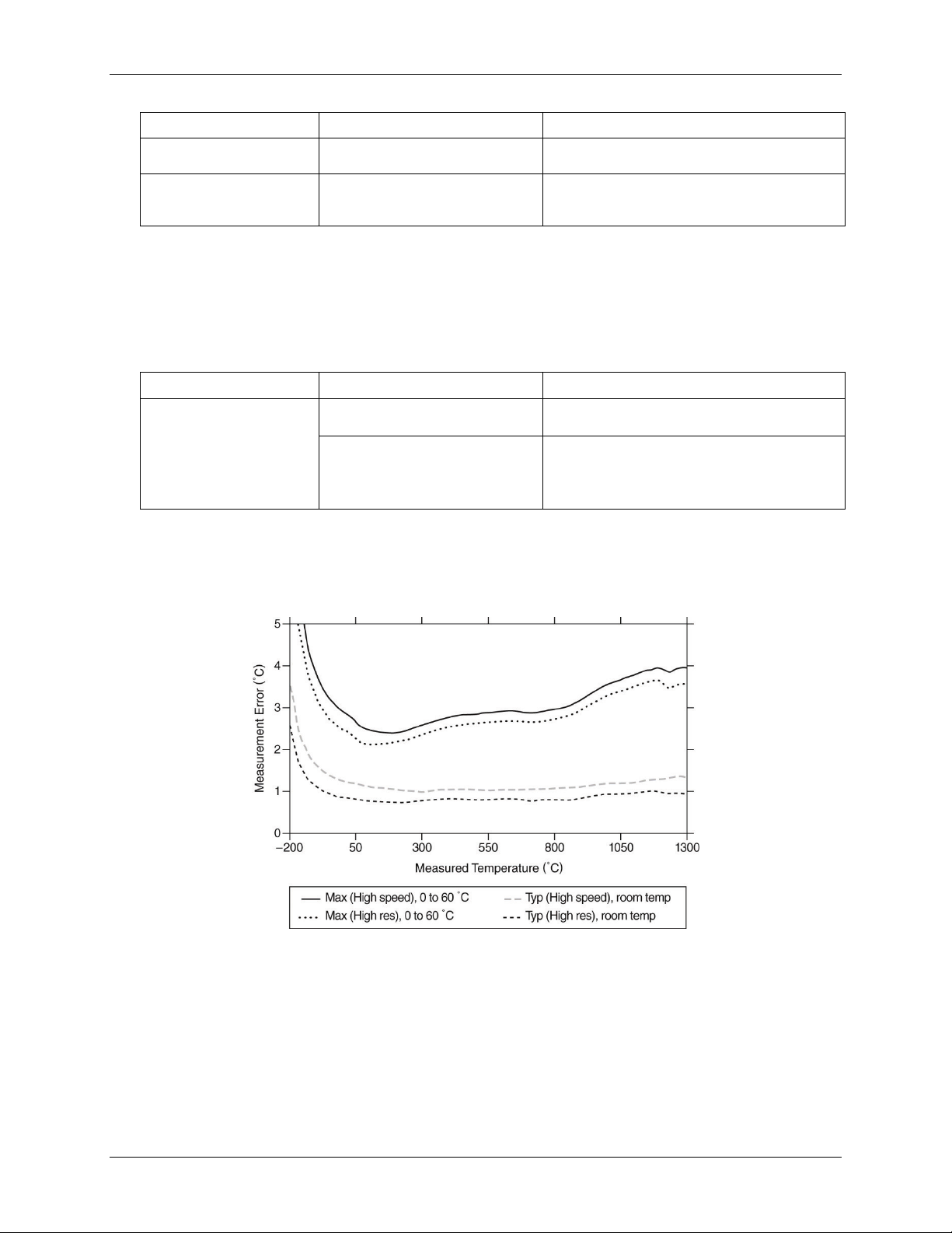
The following figures show the errors for each thermocouple type when connected to the WebDAQ 316 with
auto zeroing performed. The figures display the maximum error over a full temperature range, and the typical
error at room temperature. The figures account for gain errors, offset errors, differential and integral
nonlinearity, quantization errors, noise errors, 50 Ω lead wire resistance, and cold-junction compensation errors.
The figures do not account for the accuracy of the thermocouple itself.
Thermocouple Types J and N Errors
19
Page 20

WebDAQ 316 User's Guide Specifications
Thermocouple Type K Errors
Thermocouple Types T and E Errors
Thermocouple Type B Errors
20
Page 21

WebDAQ 316 User's Guide Specifications
Digital type
CMOS (Schmitt trigger) input / open drain output
Number of I/O
One port of 4 bits
Configuration
Each bit can be independently configured for input or output
Power on conditions
Power on reset is input mode
Pull-up configuration
Each bit is pulled up to 5 V with a 100 kΩ resistor
Input frequency range
DC – 10 kHz (Note 1)
Input high voltage threshold
1.9 V min, 3.6 V max
Input low voltage threshold
2.3 V max, 1.0 V min
Schmitt trigger hysteresis
0.6 V min, 1.7 V max
Input high voltage limit
15 V max
–0.5 V absolute min
0 V recommended min
0 V to +5 V (no external pull up resistor)
0 V to +15 V max (Note 2)
Output off state leakage
current
capability
Output transistor onresistance (drain to source)
Thermocouple Types R and S Errors
Digital input/output
Table 3. Digital input/output specifications
Parameter Specification
Input low voltage limit
Output voltage range
10 µA max
Output sink current
Note 1: Applying a signal with a frequency higher than this specification will adversely affect system performance and
could cause errors.
Note 2: The external pull-up resistor is connected between the digital output bit and an external supply. Adding an external
pull-up resistor connects it in parallel with the internal 100 kΩ pull-up resistor of that particular digital
input/output bit to the internal 5 V supply. Careful consideration should be made when considering the external
pull-up resistor value and the resultant pull-up voltage produced at the load.
100 mA max (continuous) per output pin
1.6 Ω
21
Page 22

WebDAQ 316 User's Guide Specifications
100 Base-TX
10 Base-T
Communication rates
10/100 Mbps, auto-negotiated
Connector
RJ-45, 8 position
Cable length
100 meters (328 feet) max
Additional parameters
HP Auto-MDIX support
DHCP, link-local, static
back to link-local and request the IP address 169.254.100.100.
The default name is webdaq-xxxxxx, where xxxxxx are the lower 6 digits of the
device MAC address. This name may be changed using the web interface.
Network name publication
By mDNS
Factory default IP address
192.168.0.101
Factory default subnet mask
255.255.255.0
Factory default Gateway
192.168.0.1
Factory default DHCP
setting
Factory default password
admin, case sensitive; can be modified with the web interface
Factory default user name
admin, case sensitive; cannot be changed.
Microprocessor
Type: Quad core Broadcom BCM2837
Memory
RAM: 1 GB LPDDR2
Network
Ethernet connection
Table 4. Ethernet connection specifications
Parameter Specification
Ethernet type
Network interface
Table 5. Factory default specifications
Parameter Specification
Network IP configuration
Network name
DHCP may be disabled by the user and a static IP address assigned
If DHCP is enabled but is unsuccessful at obtaining an IP address, the device will fall
Network factory default settings
Table 6. Factory default specifications
Parameter Specification
DHCP + link-local enabled
Processor / Memory
Table 7. Processor / memory specifications
Parameter Specification
Speed: 1.2 GHz
Flash: 4 GB eMMC (3 GB available for user data storage)
22
Page 23

WebDAQ 316 User's Guide Specifications
Number of USB ports
Two
USB device type
USB 2.0 (high-speed)
Device compatibility
USB 1.1, USB 2.0, USB 3.0
Memory card type
SD, SDHC, SDXC, MMC, TransFlash
File systems supported
FAT16, FAT32, exFAT, ext2/3/4, NTFS
1: POWER
Steady yellow
Device is booting up.
Steady green
Device boot is successful.
Blinking yellow
Device is shutting down.
Off
Device is off.
2: STATUS
Blinking yellow
Device is configuring hardware.
Steady green
Hardware configuration is complete.
Flashing green
Waiting for the schedule start condition to be met. (Note 4)
Blinking
The configured schedule start condition is met; waiting for job start
Blinking green
The configured job start condition is met – the job is running. (Note 4)
Off
Device is off.
3: ERROR
Blinking yellow
Error condition is detected. LED blinks even when the software is
Error state is cleared on the next schedule start.
Off
No error is detected, or the device is off
4: MEDIA
Blinking yellow
A job is configured to log to external media, but the job hasn't started
yet; push button will not let you eject media.
Steady yellow
External media is inserted into the SD card slot or USB storage port.
Blinking green
Currently logging to an external SD card or USB storage device.
Steady green
Media has been made safe for removal using the FUNC button, but is
still inserted in the device.
Off
No external media is detected, or the device is off.
USB ports
Table 8. USB specifications
Parameter Specification
Note 3: The USB ports are provided for connection to a mass storage device.
SD memory card slot
Table 9. SD card specifications
Parameter Specification
LED indicators
Table 10. LED specifications – normal operating mode
Label State Description
100 ms on,
2s off
heartbeat
condition to be met. (Note 4)
configured to ignore the error.
Note 4: Use the WebDAQ software to configure start and stop settings for jobs and schedules.
23
Page 24

WebDAQ 316 User's Guide Specifications
All LEDs
Solid yellow
Software update is starting.
1. POWER
Blinking yellow
Software update is running.
2. STATUS
Blinking green
Update file is located; device is being updated.
Blinking yellow
Update file cannot be located; insert media containing the update file.
3. ERROR
Blinking green
Update is successful; device reboot in approximately 5 seconds.
Blinking yellow
Update failed; user must retry.
Power button
POWER
Variable function:
Function button
FUNC
Dual function:
interface
Factory reset button
CONFIG
Restores network settings to factory default values
Ground connector
#6-32
Connector port for recommended #6-32 ground screw
Input voltage
Center positive
6 VDC to 16 VDC
Input wattage
4 W typ, 10 W max
External power adapter
MCC p/n PS9V1AEPS230V
9 V, 1.67 A, 110 VAC to 240 VAC input range
Battery
One 3 V button cell lithium battery (BR1225 or CR1225) required to
maintain time of day clock when device is powered off.
Table 11. LED specifications – software update mode
LED State Description
Push buttons
Table 12. Push button specifications
Component Label Description
Press briefly: turns the device on
Press for ~1 second: shuts down the device; release the button when
the POWER LED blinks yellow
Press and hold ~4 seconds: forces the device to power off
Ejects, or safely unmounts, all removable media for safe removal
from the device (default)
o This function is disabled when a job that uses external media is
running
o The MEDIA LED is steady green when all media is unmounted
but still inserted in the device
Starts or stops an acquisition; requires configuration via the web
RESET
Ground connector
Table 13. Ground connector specifications
Component Label Description
Power
Table 14. Power specifications
Parameter Conditions Specification
24
Page 25

WebDAQ 316 User's Guide Specifications
Dimensions (L × W × H)
158.8 × 146.1 × 38.1 mm (6.25 × 5.75 × 1.50 in.)
177.0 × 146.1 × 38.1 mm (6.97 × 5.75 × 1.50 in.) includes spring terminal
Weight
635 g (1.45 lb)
Operating temperature range
0 °C to 50 °C max
Storage temperature range
–40 °C to 85 °C
Ingress protection
IP30
Operating humidity
10% to 90% RH, noncondensing
Storage humidity
5% to 95% RH, noncondensing
Maximum altitude
2,000 m (6,562 ft)
Pollution Degree
2
Between any two terminals
±30 V max
Channel-to-channel isolation
None
Channel-to-earth ground
Continuous
250 Vrms, Measurement Category II (Note 6)
Withstand
2300 Vrms, verified by a 5 second dielectric withstand test
Connector types
36-position spring terminal for thermocouple connections
6-position screw terminal for digital connections
Terminal wiring
18 to 28 AWG copper conductor wire with 7 mm (0.28 in.) of insulation stripped from the
Mechanical
Table 15. Mechanical specifications
Parameter Specification
Environmental
Table 16. Environmental specifications
Parameter Specification
Note 5: WebDAQ 316 operation is intended for indoor use only, but may be used outdoors if installed in a suitable
enclosure.
Safety voltages
Connect only voltages that are within the limits specified in this table.
Table 17. Safety specifications
Parameter Conditions Specification
isolation
Note 6: Measurement Category II is for measurements performed on circuits directly connected to the electrical
distribution system. This category refers to local-level electrical distribution, such as that provided by a standard
wall outlet, for example 115 V for US or 230 V for Europe.
Caution! Do not connect the device to signals or use for measurements within Measurement Categories
III or IV.
Signal connectors
Table 18. Screw terminal specifications
Parameter Specification
end
25
Page 26

WebDAQ 316 User's Guide Specifications
#
Label
Use # Label
Use
1
GND
Digital ground
4
DIO2
Digital bit 2
3
DIO1
Digital bit 1
6
GND
Digital ground
#
Label
Use # Label
Use 1 NC
No connection
29
NC
No connection
2
TC0[+]
Channel 0 HI
30
TC0[–]
Channel 0 LO
3
TC1[+]
Channel 1 HI
31
TC1[–]
Channel 1 LO
4
TC2[+]
Channel 2 HI
32
TC2[–]
Channel 2 LO
5
TC3[+]
Channel 3 HI
33
TC3[–]
Channel 3 LO
6
TC4[+]
Channel 4 HI
34
TC4[–]
Channel 4 LO
8
TC6[+]
Channel 6 HI
36
TC6[–]
Channel 6 LO
10
TC8[+]
Channel 8 HI
38
TC8[–]
Channel 8 LO
11
TC9[+]
Channel 9 HI
39
TC9[–]
Channel 9 LO
12
TC10[+]
Channel 10 HI
40
TC10[–]
Channel 10 LO
13
TC11[+]
Channel 11 HI
41
TC11[–]
Channel 11 LO
14
TC12[+]
Channel 12 HI
42
TC12[–]
Channel 12 LO
15
TC13[+]
Channel 13 HI
43
TC13[–]
Channel 13 LO
17
TC15[+]
Channel 15 HI
45
TC15[–]
Channel 15 LO
Screw terminal
Table 19. Screw terminal pinout
Terminal Terminal
2 DIO0 Digital bit 0 5 DIO3 Digital bit 3
Spring terminal
Table 20. Spring terminal pinout
Terminal Terminal
7 TC5[+] Channel 5 HI 35 TC5[–] Channel 5 LO
9 TC7[+] Channel 7 HI 37 TC7[–] Channel 7 LO
16 TC14[+] Channel 14 HI 44 TC14[–] Channel 14 LO
18 COM Common 46 COM Common
26
Page 27

EU Declaration of Conformity
According to ISO/IEC 17050-1:2010
Manufacturer: Measurement Computing Corporation
Address: 10 Commerce Way
Norton, MA 02766
USA
Product Category: Electrical equipment for measurement, control and laboratory use.
Date and Place of Issue: May 31, 2017, Norton, Massachusetts USA
Test Report Number: EMI7018.17
Measurement Computing Corporation declares under sole responsibility that the product
WebDAQ 316
is in conformity with the relevant Union Harmonization Legislation and complies with the essential
requirements of the following applicable European Directives:
Electromagnetic Compatibility (EMC) Directive 2014/30/EU
Low Voltage Directive 2014/35/EU
RoHS Directive 2011/65/EU
Conformity is assessed in accordance to the following standards:
EMC:
Emissions:
EN 61326-1:2013 (IEC 61326-1:2012), Class A
EN 55011: 2009 + A1:2010 (IEC CISPR 11:2009 + A1:2010), Group 1, Class A
Immunity:
EN 61326-1:2013 (IEC 61326-1:2012), Controlled EM Environments
EN 61000-4-2:2008 (IEC 61000-4-2:2008)
EN 61000-4-3 :2010 (IEC61000-4-3:2010)
EN 61000-4-4 :2012 (IEC61000-4-4:2012)
EN 61000-4-5 :2014 (IEC61000-4-5:2014)
EN 61000-4-6 :2013 (IEC61000-4-6:2013)
EN 61000-4-11:2004 (IEC61000-4-11:2004)
Safety:
EN 61010-1 (IEC 61010-1)
Environmental Affairs:
Articles manufactured on or after the Date of Issue of this Declaration of Conformity do not contain any of the
restricted substances in concentrations/applications not permitted by the RoHS Directive.
Carl Haapaoja, Director of Quality Assurance
Page 28

Measurement Computing Corporation NI Hungary Kft
10 Commerce Way H-4031 Debrecen, Hátar út 1/A, Hungary
Norton, Massachusetts 02766 Phone: +36 (52) 515400
(508) 946-5100 Fax: +36 (52) 515414
Fax: (508) 946-9500 http://hungary.ni.com/debrecen
E-mail: info@mccdaq.com
www.mccdaq.com
 Loading...