

Page 1
1-844-969-4247
support@modularclosets.com
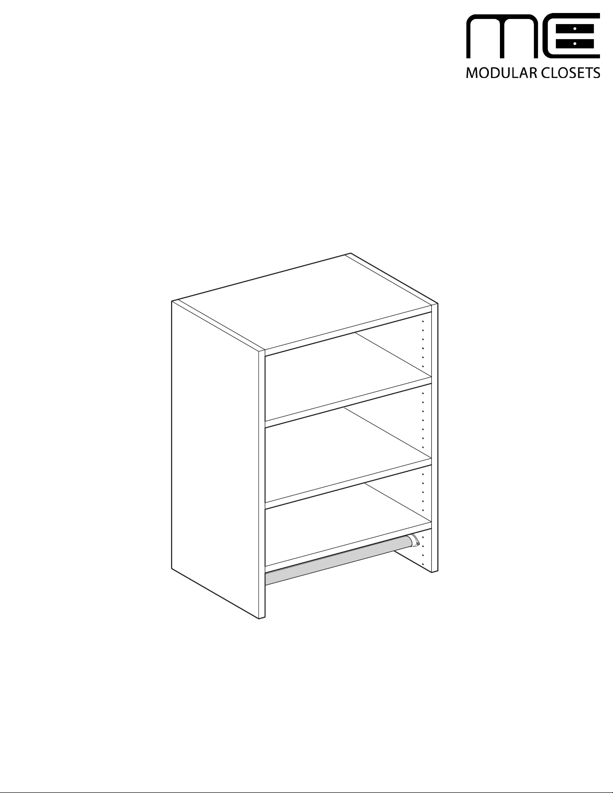
MEDIUM HANGING UNIT
18" / 24" / 30" / 36"
ASSEMBLY AND INSTALLATION
INSTRUCTIONS
Page 2
ASSEMBLY AND INSTALLATION INSTRUCTIONS
MEDIUM HANGING UNIT - 18" / 24" / 30" / 36"
1
AB
Left Side Panel
A
Right Side Panel
B
Set Shelf (Qty 2)
C
Adjustable Shelf (Qty 2)
D
Rear Cleat (Qty 2)
E
Hanging Rod (Qty 1)
F
"O" Rod Bracket (Qty 1)
G
PARTS LIST
H
I
J
K
L
M
CD
FRONT
FRONT
FINISHED EDGE
"U" Rod Bracket (Qty 1)
Cam Post (Qty 16)
Camlock (Qty 16)
Screw (Qty 4)
Shelf Pins (Qty 8)
Screws, 3" (Qty 6)
FINISHED EDGE
FINISHED EDGE
E
F
HG
IJK
M
TOOLS REQUIRED
(purchased separately)
NOLevel
Stud Finder
PQDrill, 3/32" bit size
Phillips Screwdriver
N
O
P
Q
L
1.1
Lay parts out on a protective surface to prevent damage.
protective surface.
1.2
Inventory parts against the Parts List. Make sure all parts are present before proceeding.
Tip: Spread out the cardboard packaging to use as a
Page 3
ASSEMBLY AND INSTALLATION INSTRUCTIONS
MEDIUM HANGING UNIT - 18" / 24" / 30" / 36"
2
I
3
I
A
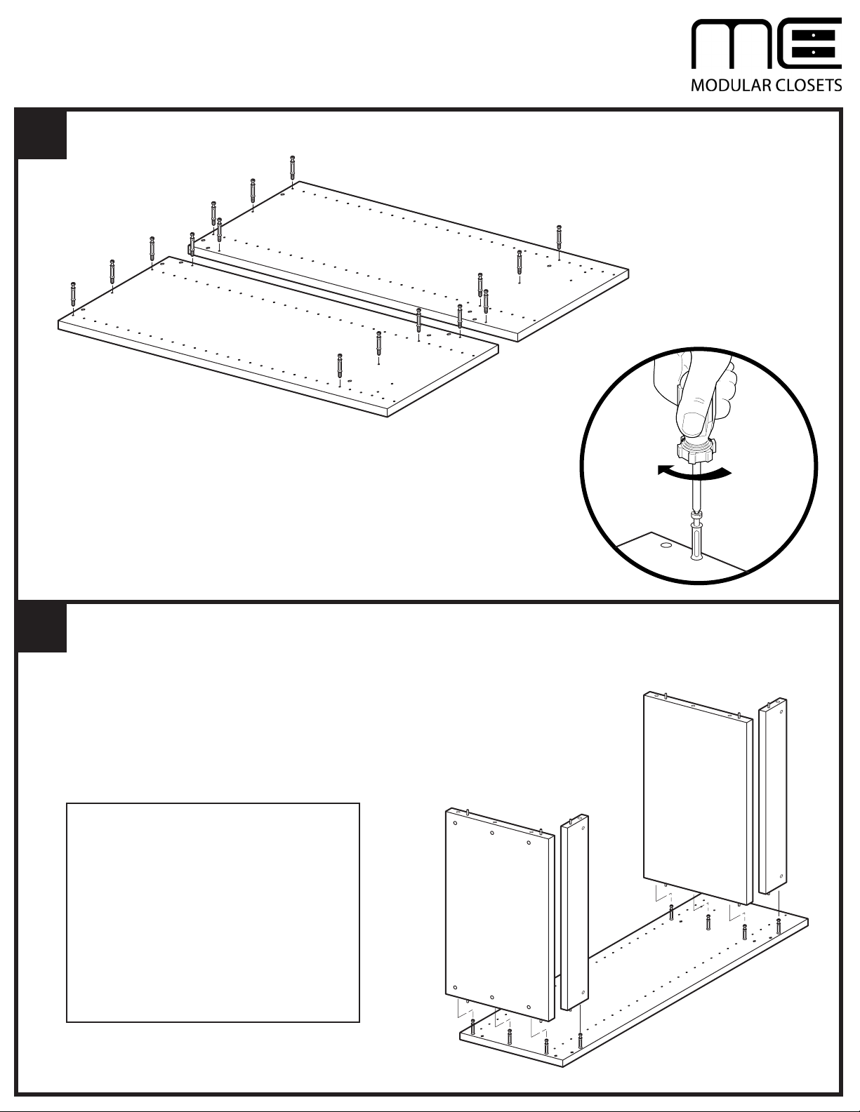
2.1 Install one Cam Post (I) into each of the eight holes on Left Side Panel (A)
and Right Side Panel (B). Tighten until Cam Posts are seated against Side
Panels.
3.1 Assemble Set Shelves (C) and Rear Hanging Cleats (E) onto Right Side Panel (B)
by sliding the Shelves and Cleats onto the Cam Posts (I) on Right Side Panel. BE
SURE dowel pins in Shelves and Cleats engage drilled holes in Right Side Panel,
and all parts are pressed flush against Right Side Panel.
B
C
E
IMPORTANT NOTES
Install Set Shelves (C) with finished edges
facing forward (toward front of unit).
Install Rear Hanging Cleats (E) with holes
for Cam Locks facing the rear of the unit and
the unfinishededge against the Set Shelf (C).
Install upper Set Shelf (C) with holes for Cam
Locks facing the top of the unit.
Install lower Set Shelf (C) with holes for Cam
Locks facing the bottom of the unit.
C
E
I
I
B
Page 4

ASSEMBLY AND INSTALLATION INSTRUCTIONS
MEDIUM HANGING UNIT - 18" / 24" / 30" / 36"
4
3.1 Install Left Side Panel (A) onto
assembled Set Shelves (C) and
Rear Hanging Cleats (E). BE SURE
dowel pins in Shelves and Cleats
engage drilled holes in Left Side
Panel, and Left Side Panel is pressed
flush against Set Shelves and Cleats.
C
E
A
E
C
B
5
5.1
Insert Camlocks (J) in holes in Set Shelves (C)
and Rear Hanging Cleats (E), with arrow pointing
toward Cam Post opening. Be sure Camlocks engage
Cam Posts, and are fully seated in Shelves and
Cleats.
5.2
Tighten Camlocks (J) clockwise to lock.
ARROW TOWARD
CAM POST OPENING
J
J
J
J
Page 5

ASSEMBLY AND INSTALLATION INSTRUCTIONS
MEDIUM HANGING UNIT - 18" / 24" / 30" / 36"
6
E
PILOT HOLES
STANDARD
HEIGHT
-
84" FROM
FLOOR
E
STUDS
INSTALLATION
6.1
Determine the mounting location for the unit.
6.2
Using a stud finder, locate studs to which the unit will be secured. Mark stud locations with a pencil.
6.3
With the unit positioned at the desired location, level the unit, then drill pilot holes through Rear Hanging Cleats (E),
NOTE: For 18" and 24" units, it is likely that only one stud will pass through the unit. In these cases, use two screws
through each Rear Hanging Cleat.
Page 6

ASSEMBLY AND INSTALLATION INSTRUCTIONS
MEDIUM HANGING UNIT - 18" / 24" / 30" / 36"
7
E
M
E
M
7.1 Secure Rear Hanging Cleats (E) to studs using 3" Screws (M).
Page 7

ASSEMBLY AND INSTALLATION INSTRUCTIONS
DOUBLE HANGING UNIT - 24" / 30" / 36"
8
A
K
K
H
8.1 Position "U" Bracket (H) on Left Side Panel (A) and secure Bracket with two screws (K).
H
Page 8

ASSEMBLY AND INSTALLATION INSTRUCTIONS
MEDIUM HANGING UNIT - 18" / 24" / 30" / 36"
9
F
F
K
K
G
NOTE: Use care when installing Hanging Rod (F) to avoid scratching finish inside unit.
9.1
Insert one end of Hanging Rod (F) into "O" Bracket (G).
9.2
Slide assembled Hanging Rod (F) and "O" Bracket (G) into unit. Rest free end of Hanging Rod in "U" Bracket.
G
B
9.3
Secure "O" Bracket (G) to Right Side Panel (B) with two Screws (K).
Page 9

ASSEMBLY AND INSTALLATION INSTRUCTIONS
MEDIUM HANGING UNIT - 18" / 24" / 30" / 36"
10
10.1
10.2
For each Adjustable Shelf (D), insert
four Shelf Pins (L) into pin holes inside
the Tower at the desired height.
Rest Adjustable Shelves (D) on Shelf
Pins (L).
D
L
L
L
L
 Loading...