

Page 1
Operating Manual
Electronic Temperature Controller
Type TRN, TRN/20, TRM, TRM/20,
TRH and TRH /20
Gas sampling and conditioning technology 2-5.1.2-ME
Page 2

2
Dear Customer,
we have made up this operating manual in such a way that all necessary information about the
product can be found and understood quickly and easily.
Should you still have any question, please do not hesitate to contact M&C directly or go through your
appointed dealer. Respective contact addresses are to be found in the annexe to this operating
manual.
Please also contact our homepage www.mc-techgroup.com
for further information about our
products. There, you can read or download the data sheets and operating manuals of all M&C
products as well as further information in German, English and French.
This Operating Manual does not claim completeness and may be
subject to technical modifications.
© 05/1995 M&C TechGroup Germany GmbH.
Reproduction of this document or its content is not allowed without
permission from M&C.
3rd Edition: 09/09
2-5.1.2-ME Gas sampling and conditioning technology
Page 3

Contents
1 General information ...................................................................................................................... 4
2 Declaration of conformity ............................................................................................................. 4
3 Safety instructions ........................................................................................................................ 5
4 Warranty ......................................................................................................................................... 5
5 Used terms and signal indications .............................................................................................. 6
6 Application ..................................................................................................................................... 7
7 Technical data ............................................................................................................................... 7
8 Description ..................................................................................................................................... 7
9 Receipt of goods and storage ...................................................................................................... 8
10 Installation instructions and dimensions ................................................................................... 8
11 Electrical connections .................................................................................................................. 9
12 Initial starting ................................................................................................................................. 9
13 Closing down ............................................................................................................................... 10
14 Maintenance and repair .............................................................................................................. 10
15 Appendix ...................................................................................................................................... 10
List of Illustrations
Figure 1 Dimensions TR... ................................................................................................................. 8
Figure 2 Connector pin assignment of the multipole socket .............................................................. 9
3
Gas sampling and conditioning technology 2-5.1.2-ME
Page 4

4
Head Office
M&C TechGroup Germany GmbH Rehhecke 79 40885 Ratingen Germany
Telephone: 02102 / 935 - 0
Fax: 02102 / 935 - 111
E - mail: info@mc-techgroup.com
www.mc-techgroup.com
1 GENERAL INFORMATION
The product described in this operating manual has been examined before delivery and left our works
in perfect condition related to safety regulations. In order to keep this condition and to guarantee a
safe operation, it is important to heed the notes and prescriptions made in this operating manual.
Furthermore, attention must be paid to appropriate transportation, correct storage, as well as
professional installation and maintenance work.
All necessary information a skilled staff will need for appropriate use of this product are given in this
operating manual.
2 DECLARATION OF CONFORMITY
CE - Certification
The product described in this operating manual complies with the following EC directives:
EMV-Instruction
The requirements of the EC directive 89/336/EWG “Electromagnetic compatibility“ are met.
Low Voltage Directive
The requirement of the EC directive 72/23/EWG “Low Voltage Directive“ are met.
The compliance with this EC directive has been examined according to DIN EN 61010 (corresponds to
IEC 61010).
Declaration of conformity
The EU Declaration of conformity can be downloaded from the M&C homepage or directly requested
from M&C.
2-5.1.2-ME Gas sampling and conditioning technology
Page 5

5
3 SAFETY INSTRUCTIONS
Please take care of the following basic safety procedures when mounting, starting up or
operating this equipment:
Read this operating manual before starting up and use of the equipment. The information and
warnings given in this operating manual must be heeded.
Any work on electrical equipment is only to be carried out by trained specialists as per the regulations
currently in force.
Attention must be paid to the requirements of VDE 0100 (IEC 364) when setting high-power electrical
units with nominal voltages of up to 1000 V, together with the associated standards and stipulations.
Check the details on the type plate to ensure that the equipment is connected to the correct mains
voltage.
Protection against touching dangerously high electrical voltages:
Before opening the equipment, it must be switched off and hold no voltages. This also applies to any
external control circuits that are connected.
The device is only to be used within the permitted range of temperatures and pressures.
Check that the location is weather-protected. It should not be subject to either direct rain or moisture.
The device must not
be used in hazardous areas.
Installation, maintenance, monitoring and any repairs may only be done by authorized personnel with
respect to the relevant stipulations.
4 WARRANTY
If the equipment fails, please contact M&C directly or else go via your appointed M&C dealer.
We offer a one year warranty as of the day of delivery as per our normal terms and conditions of sale
and assuming technically correct operation of the device. Consumables are hereby excluded. The
terms of the warranty cover repair at the factory at no cost or the replacement at no cost of the
equipment free ex user location. Reshipments must be sent in a sufficient and proper protective
packaging.
Gas sampling and conditioning technology 2-5.1.2-ME
Page 6

6
5 USED TERMS AND SIGNAL INDICATIONS
This means that death, severe physical injuries and/or important
material damages will occur in case the respective safety measures
DANGER!
WARNING!
CARE!
CARE!
ATTENTION!
NOTE!
SKILLED STAFF
are not fulfilled.
This means that death, severe physical injuries and/or important
material damages may occur in case the respective safety
measures are not fulfilled.
This means that minor physical injuries may occur in case the
respective safety measures are not fulfilled.
Without the warning triangle means that a material damage may
occur in case the respective safety measures are not met.
This means that an unintentional situation or an unintentional status
may occur in case the respective note is not respected.
These are important information about the product or parts of the
operating manual which require user’s attention.
These are persons with necessary qualification who are familiar with
installation, use and maintenance of the product.
2-5.1.2-ME Gas sampling and conditioning technology
Page 7

7
6 APPLICATION
The TR... series ready-to-plug-in, on - off electronic temperature controllers are especially suitable for
controlling electrically heated sample lines 3/4/5-N/H/M series.
7 TECHNICAL DATA
Temperature controller type TRN, TRN/20 TRM, TRM/20 TRH, TRH/20
Part No. of standard version TR. - 10 A 03 B 7000 03 B 7010 03 B 7020
Part No. of version TR./20 - 20 A 03 B 7030 03 B 7040 03 B 7050
Temperature control range
Switching capacity 10 A for TR. standard version with relay contact,
Control mode on - off controller
Temperature sensor input PT100 DIN; 2-conductor with sensor breakage status
Ambient temperature -30°C to +50°C
Storage temperature -30°C to +80°C
Electrical connection for TR. standard version
with 10 A relay contact
Electrical connection for TR./20 version
with solid state relay 20A
Power supply 230V +/-10%, 50/60Hz
Housing version/ international protection type Wall-mounting housing IP 66 EN60529
Housing material polycarbonate
Dimensions in mm see diagram 1
Weight 1,2 kg
0 - 100°C 0 - 200°C 0 - 250°C
20 A for version TR./20 with solid state relay
2.5 m connecting cable 1.5mm² with mains plug and
7-pin coupling socket for connection of the heated line:
controlled mains voltage ON/OFF and PT100 sensor
2.5 m connecting cable 2.5mm² for mains power and
5-pin coupling socket for connection of the heated line:
controlled mains voltage ON/OFF and PT100 sensor
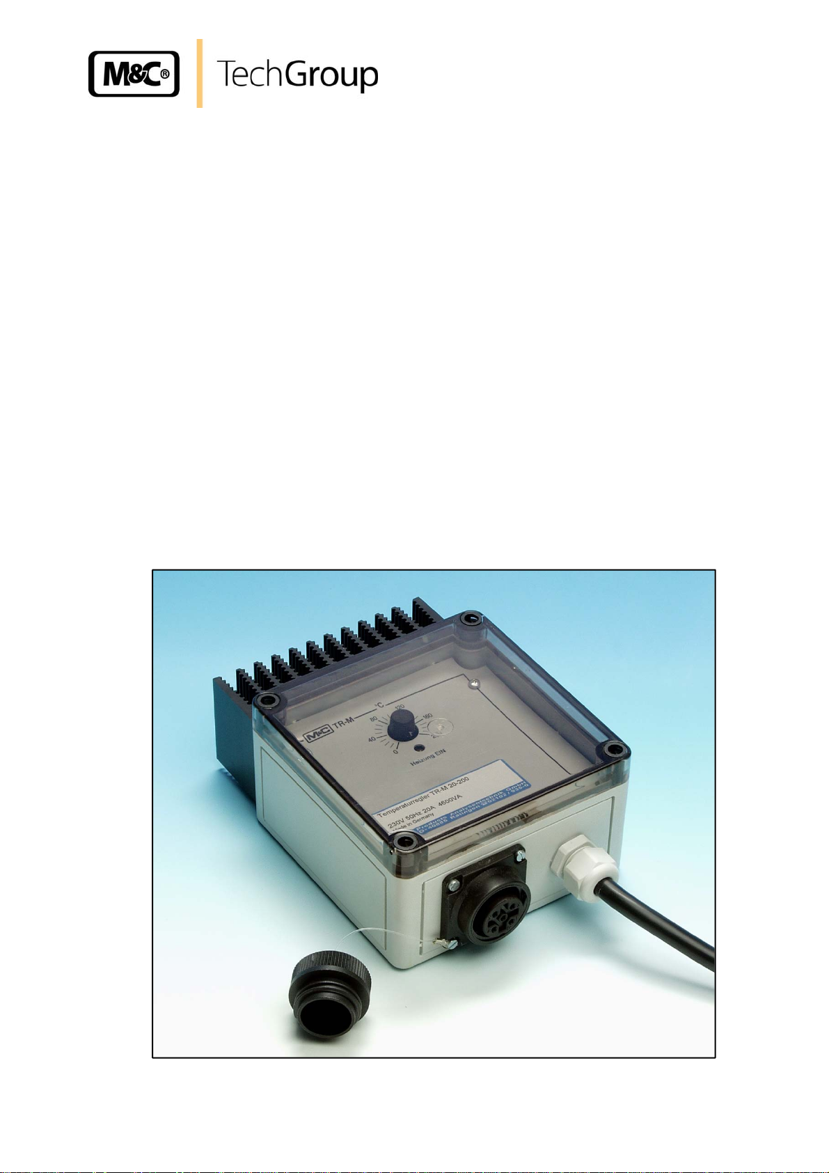
8 DESCRIPTION
The TR... series on - off electronic temperature controller is mounted in a wall-mounting housing. The
heated sample lines multipole plug with mains and PT100 sensor line is easily connected to the
multipole socket in the temperature controller's housing. The temperature controller together with plugand-socket connection is supplied in two versions. The TR. standard controller with relay contact and
7-pin coupling socket can be used up to 10 A and the TR./20 version with contactless solid-state relay
and 5-pin coupling socket up to 20 A. The temperature sensor input is designed for PT-100 sensors
and is fitted with a sensor-breakage safety status. Three temperature control ranges are available:
TRN = 0-100°C, TRM = 0-200°C, TRH = 0-250°C. The desired operating temperature can be set
using the control knob with its graduated scale. The control function is displayed by LED. A clear cover
shows the set value and the switch function, thus ensuring that the desired value has not been
changed unattended.
Gas sampling and conditioning technology 2-5.1.2-ME
Page 8

8
9 RECEIPT OF GOODS AND STORAGE
• Immediately after arrival, remove the controller and eventual accessories carefully from the packing
and check the articles for completeness against the packing list;
• Check the goods for any damage during transportation and, if required, inform your shipping
insurance immediately of the damage found.
The controller should be stored in a weather-protected and frost-free area!
NOTE!
10 INSTALLATION INSTRUCTIONS AND DIMENSIONS
Figure 1 Dimensions TR...
2-5.1.2-ME Gas sampling and conditioning technology
Page 9

11 ELECTRICAL CONNECTIONS
A wrong mains voltage can destroy the device. Please ensure that
WARNING!
the supply voltage is identical to the indication on the type plate!
9
When setting high-power electrical units with nominal voltages of
up to 1000V, attention must be paid to the requirements of VDE
0100 together with the associated standards and stipulations!
WARNING!
A main switch must be provided externally.
The main circuit of the instrument must be equipped with a fuse
corresponding to the nominal voltage (over current protection); for
electrical details see technical data.
The electrical connection is to be made to the integrated multipole socket (see figure 1).
The wattage rating of the connected device may not exceed 2,300
watt in the case of TR N/ M/ H and must be a maximum of 4,600 watt
WARNING!
in the case of TR N/ M/ H/ 20
.
Temperature controllers TRN, TRM, TRH Temperature controllers TRN/20, TRM/20, TRH/20
with 7-pin coupling socket 10A with 5-pin coupling socket 20 A
4
5 Sensor
6 Sensor
Figure 2 Connector pin assignment of the multipole socket
3
2 Mains
N
1 Mains
L
3 Sensor 2 Mains
4 Sensor
1 Mains
L
N
12 INITIAL STARTING
The temperature control device may only be used with the stated PT-100 sensor.
The TR.. series temperature control devices are easy to mount and are ready for immediate use:
• Connect mains with the multipole plug at the controllers coupling socket. See diagram 2.
• The TR N /M /H [10 A] temperature controllers have a 2.5 m long connecting cable 1,5mm2
fitted with an earthing contact plug, which is connected with an adequately fused socket.
The TR N /M /H /20
2.5mm², which is connected to an adequately fused mains supply.
• Select the desired temperature with the control knob on the front panel.
Gas sampling and conditioning technology 2-5.1.2-ME
[20 A] temperature control devices have a 2.5 m long connecting cable
Page 10

10
• Check whether the controller is functioning properly:
Set maximum desired temperature ⇒ yellow LED lights up
When the desired temperature is reached ⇒ controller switches heating off, yellow LED goes
out.
On installation, the controller should basically be checked to see whether it switches at the set values
and reaches the desired operating temperature.
13 CLOSING DOWN
No special measures are to be taken for closing down the equipment.
14 MAINTENANCE AND REPAIR
The controller TR... are working maintenance-free for a long period of time.
In case the controller is defective, please send the device to M&C for repair.
The controller is equipped with a sensor break protection that in case of
need cuts off the unit as long as the defective sensor has not been
exchanged.
NOTE!
15 APPENDIX
Further product documentation can be seen and downloaded from our home page:
www.mc-techgroup.com
2-5.1.2-ME Gas sampling and conditioning technology
 Loading...