

Page 1
Portable Gas Conditioning Unit Series
PSS
®
PSS-5C, PSS-5/2C, PSS-5/3C
Instruction Manual
Version 1.02.02
Page 2

This instruction manual does not claim completeness and may be subject
to technical modifications.
©
Germany GmbH. Reproduction of this
document or its content is not allowed without permission from
PSS
Version: 1.0
Dear customer,
Thank you for buying our product. In this manual you will find all necessary information about this
M&C product. The information in the manual is fast and easy to find, so you can start using your M&C
product right after you have read the manual.
If you have any question regarding the product or the application, please don’t hesitate to contact
M&C or your M&C authorized distributor. You will find all the addresses in the appendix of this
instruction manual.
For additional information about our products, please go to M&C’s website www.mc-techgroup.com
There you can find the data sheets and manuals of our products in German and English.
.
11/2019 M&C Techgroup
®
is a registered trade mark.
2.02
2 PSS-5C | 1.02.02 www.mc-techgroup.com
M&C.
Page 3

List of Contents
1 General information .................................................................................................................. 5
2 Declaration of conformity ......................................................................................................... 5
3 Safety instructions .................................................................................................................... 6
4 Warranty .................................................................................................................................... 6
5 Used terms and signal indications .......................................................................................... 7
5.1 Type plate and labels on the device ..................................................................................... 8
6 Introduction ............................................................................................................................. 10
7 Function of the M&C Jet-Stream Heat Exchanger ................................................................ 10
8 Application .............................................................................................................................. 11
9 Technical data ......................................................................................................................... 13
10 Dimensions .......................................................................................................................... 18
11 Description ........................................................................................................................... 18
12 Operating instructions ........................................................................................................ 21
12.1 Main Menu ......................................................................................................................... 21
12.2 PIN Entry ........................................................................................................................... 22
12.3 Set Point Entry ................................................................................................................... 23
13 Parameter Setting ................................................................................................................ 24
13.1 Setting Temperature Alarm Limits ...................................................................................... 25
13.2 Fan Speed Setting ............................................................................................................. 26
13.3 Brightness Setting of Display ............................................................................................. 26
14 mA Output for the Temperature Measurement inside the Cooling Block ........................ 27
14.1 mA Output Range Selection ............................................................................................... 27
14.2 mA Output Calibration for the Temperature Measurement inside the Cooling Block .......... 27
15 Liquid Alarm Sensor (LA) type LA1S ................................................................................. 29
15.1 Activating the LA ................................................................................................................ 29
15.2 LA Sensitivity adjustment ................................................................................................... 30
15.3 LA Calibration .................................................................................................................... 31
16 Receipt of goods and storage ............................................................................................ 32
17 Installation instructions ...................................................................................................... 33
18 Supply connections ............................................................................................................ 34
18.1 Tube connections ............................................................................................................... 34
18.1.1 Connecting the heated sample line with special adapter (option) ................................ 36
18.2 Electrical connections ........................................................................................................ 36
19 Commissioning ................................................................................................................... 39
20 Closing down ....................................................................................................................... 40
21 Maintenance ......................................................................................................................... 41
22 Trouble shooting ................................................................................................................. 42
23 Spare parts list .................................................................................................................... 44
24 Appendix .............................................................................................................................. 46
www.mc-techgroup.com PSS-5C | 1.02.02 3
Page 4

List of Figures
Figure 1 Type plate ......................................................................................................................... 8
Figure 2 Labelling of the connections ............................................................................................. 8
Figure 3 Warning label on the device.............................................................................................. 9
Figure 4 Diagram of the heat exchanger function ......................................................................... 10
Figure 5 Gas flow diagram of PSS-5C and PSS-5/3C .................................................................. 11
Figure 6 Gas flow diagram of PSS-5/2C ....................................................................................... 12
Figure 7 Dimensions ..................................................................................................................... 18
Figure 8 Case content: PSS-5C and PSS-5/3C ............................................................................ 19
Figure 9 Navigating through the main menu ................................................................................. 21
Figure 10 Reaching the set point entry from the ECP1000C/ECP3000C main menu ..................... 23
Figure 11 Temperature alarm limits and hysteresis ........................................................................ 25
Figure 12 LA alarm limits ............................................................................................................... 30
Figure 13 PSS-5C and PSS-5/3C medium connections ................................................................. 34
Figure 14 Connecting the heated sample line with special adapter (option) ................................... 36
Figure 15 Electrical connection ...................................................................................................... 37
Figure 16 Circuit diagram PSS-5C ................................................................................................. 47
4 PSS-5C | 1.02.02 www.mc-techgroup.com
Page 5

HEAD OFFICE
M&C TechGroup Germany GmbH Rehhecke 79 40885 Ratingen Germany
Telephone: 02102 / 935 – 0
Fax: 02102 / 935 – 111
E - mail: info@mc-techgroup.com
www.mc-techgroup.com
1 General information
The product described in this instruction manual has been built and tested in our production facility.
All M&C products are packed to be shipped safely. To ensure the safe operation and to maintain the
safe condition, all instructions and regulations stated in this instruction manual need to be followed.
This instruction manual includes all information regarding proper transportation, storage, installation,
operation and maintenance of this product by qualified personnel.
Follow all instructions and warnings closely.
Read this manual carefully before commissioning and operating the device. If you have any questions
regarding the product or the application, please don’t hesitate to contact M&C or your M&C authorized
distributor.
2 Declaration of conformity
CE - Certification
The product described in this operating manual complies with the following EU directives:
EMC-Instruction
The requirements of the EU directive 2014/30/EU “Electromagnetic compatibility“ are met.
Low Voltage Directive
The requirement of the EU directive 2014/35/EU “Low Voltage Directive“ are met.
The compliance with this EU directive has been examined according to DIN EN 61010.
RoHS Directive
The requirements of the RoHS2 (‘Restriction of Hazardous Substances 2’) directive 2011/65/EU and its
annexes are met.
Declaration of conformity
The EU Declaration of conformity can be downloaded from the M&C homepage or directly requested
from M&C.
www.mc-techgroup.com PSS-5C | 1.02.02 5
Page 6

3 Safety instructions
Follow these basic safety procedures when mounting, starting up or operating this equipment:
Read this instruction manual before starting up and use of the equipment. The information and
warnings given in this instruction manual must be heeded.
Any work on electrical equipment is only to be carried out by trained specialists as per the regulations
currently in force.
The installation and commissioning of the device must conform to the requirements of VDE 0100 (IEC
364) ‘Regulations on the Installation of Power Circuits with Nominal Voltages below 1000 V’ and must
be in compliance with all relevant regulations and standards.
Check the details on the type plate to ensure that the equipment is connected to the correct mains
voltage.
Protection against touching dangerously high electrical voltages:
Before opening the equipment, it must be switched off and hold no voltages. This also applies to any
external control circuits that are connected.
The device is only to be used within the permitted range of temperatures and pressures.
Ensure sun-protected installation.
The unit may only be operated upright and with the door closed. Unused connectors must be closed
with the appropriate caps. IP42 means protection against foreign objects ≥1 mm and dripping water
up to an angle of ≤ 15°.
Do not use the gas conditioning systems PSS-5C, PSS-5/2C and PSS-5/3C in hazardous areas.
Installation, maintenance, inspections and any repairs of the devices must be carried out only by
qualified skilled personnel in compliance with the current regulations.
4 Warranty
In case of a device failure, please contact immediately M&C or your M&C authorized distributor.
We have a warranty period of 12 months from the delivery date. The warranty covers only
appropriately used products and does not cover the consumable parts. Please find the complete
warranty conditions in our terms and conditions.
The warranty includes a free-of-charge repair in our production facility or the free replacement of the
device. If you return a device to M&C, please be sure that it is properly packaged and shipped with
protective packaging. The repaired or replaced device will be shipped free of delivery charges to the
point of use.
6 PSS-5C | 1.02.02 www.mc-techgroup.com
Page 7
5 Used terms and signal indications
This means that death, severe physical injuries and/or important
This means that death, severe physical injuries and/or important
ety
This means that minor physical injuries may occur in case the
CAUTION
Without the warning triangle means that a material damage may
ATTENTION
This means that an unintentional situation or an unintentional status
These are important information about the product or parts of the
QUALIFIED PERSONNEL
These are persons with necessary qualification who are familiar with
High voltages!
Corrosive!
Wear protective gloves!
objects or extremely high
Wear safety glasses!
objects.
material damages will occur in case the respective safety measures
DANGER
WARNING
CAUTION
are not fulfilled.
material damages may occur in case the respective saf
measures are not fulfilled.
respective safety measures are not fulfilled.
occur in case the respective safety measures are not met.
NOTE
may occur in case the respective note is not respected.
operating manual which require user’s attention.
installation, use and maintenance of the product.
Protect yourself and others against damages which might be caused
by high voltages.
These substances destroy living tissue and equipment upon contact.
Do not breathe vapors; avoid contact with skin and eyes.
Working with chemicals, sharp
temperatures requires wearing protective gloves.
Protect your eyes while working with chemicals or sharp
Wear safety glasses to avoid getting something in your eyes.
www.mc-techgroup.com PSS-5C | 1.02.02 7
Page 8
Wear protective clothes!
Working with chemicals, sharp objects or extreme
ly high
1 Serial number
4 S/N: digits 3+4: Month 01
2 Electrical connection data
5 S/N digits 5 to 8: consecutive number
3 S/N: digits 1+2: Year 2018
temperatures requires wearing protective clothes.
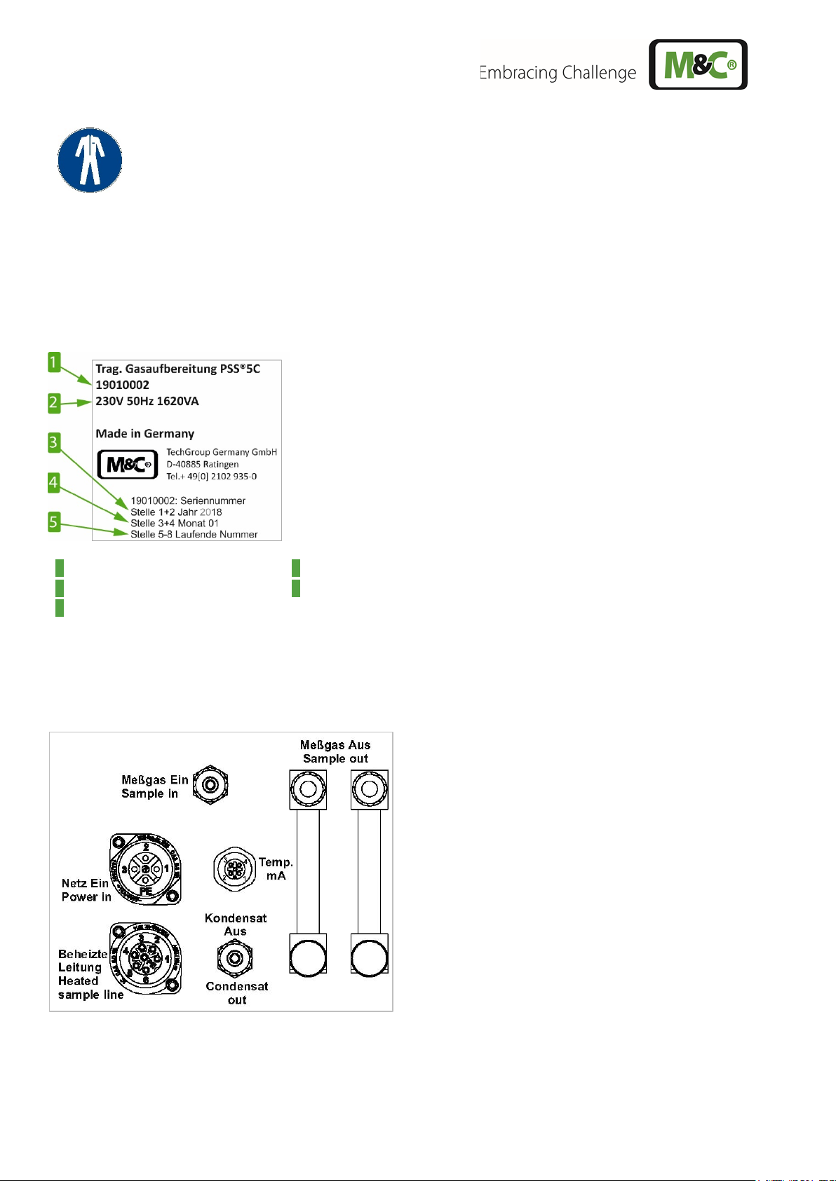
5.1 Type plate and labels on the device
A type plate, an information label and a warning label are located on the device.
The type plate contains the product name, the serial number including explanation, electrical connection
data and the manufacturer's address.
Figure 1 Type plate
The position of the electrical connections and gas connections are explained on the label below the
connections on the case side.
Figure 2 Labelling of the connections
8 PSS-5C | 1.02.02 www.mc-techgroup.com
Page 9

The warning label indicates the necessary requirements for operating the device.
Figure 3 Warning label on the device
www.mc-techgroup.com PSS-5C | 1.02.02 9
Page 10
6 Introduction
+5°C
Sample gas
out
Sample gas
in
Condensate
out
Coolingblock
[41 °F]
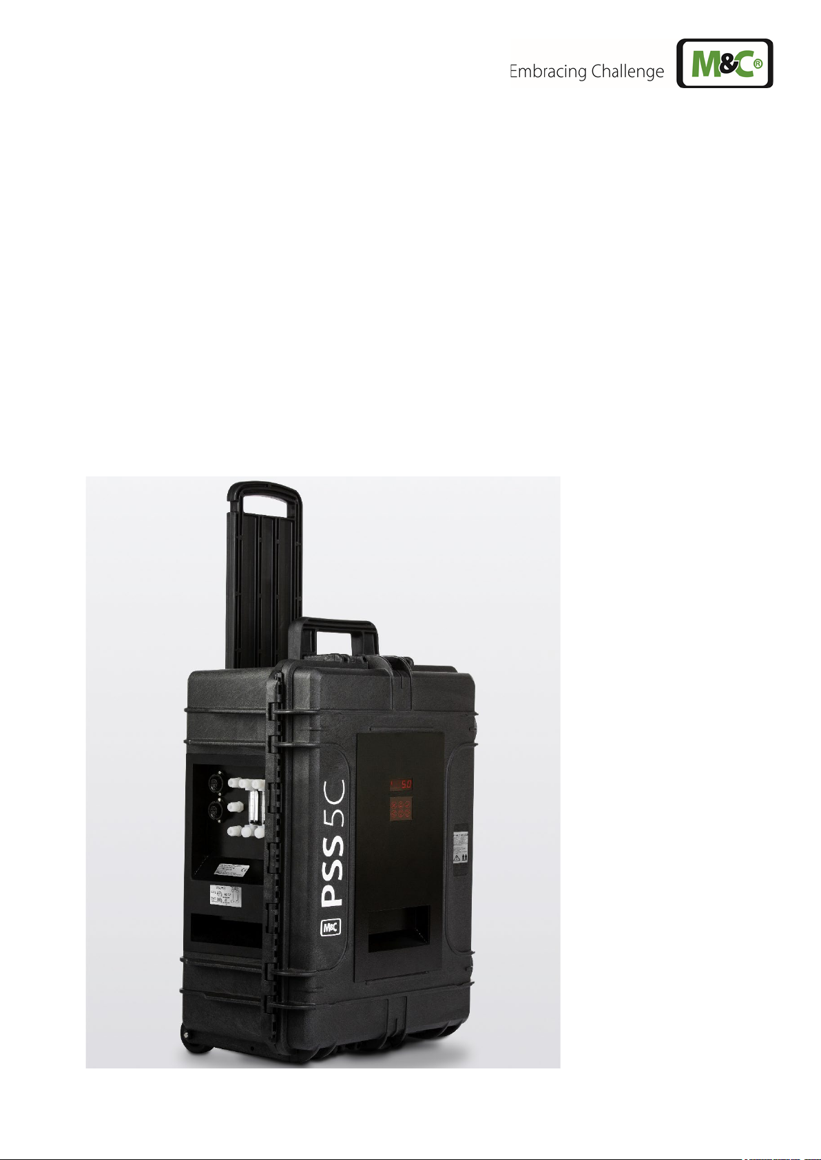
The portable gas conditioning systems PSS-5C, PSS-5/2C and PSS-5/3C are designed especially for
applications where accurate gas analysis at constantly changing locations is required.
The entire gas conditioning system is housed in a compact and impact-resistant plastic case equipped
with an integrated trolley with extendable handle. This allows gas analysis at various locations to be
carried out quickly, reliably and with low maintenance.
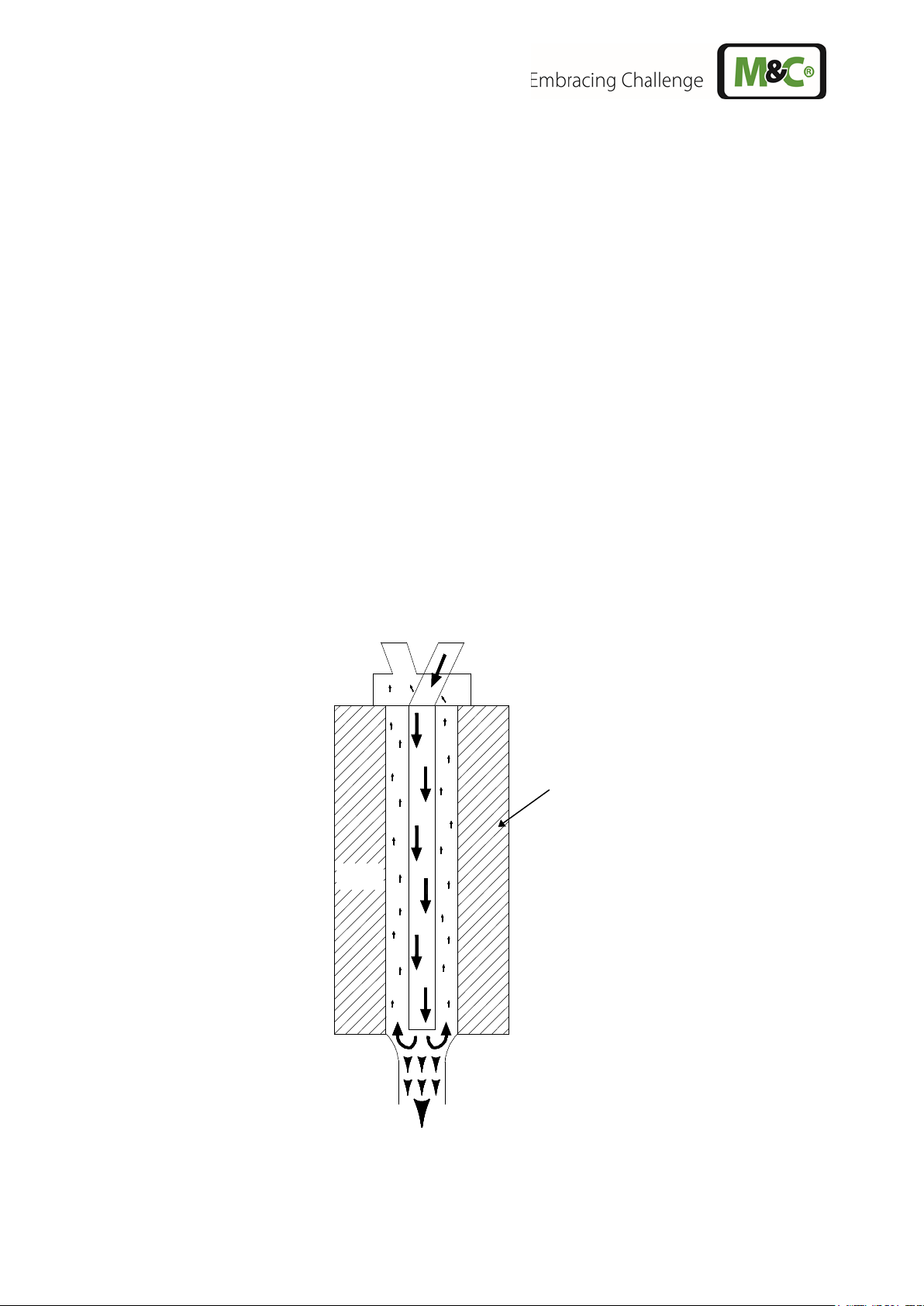
7 Function of the M&C Jet-Stream Heat Exchanger
The ECPX000C gas coolers, specially developed for analysis technology, are designed for maximum
flow rates of up to 350 Nl/h. They are also installed as system assemblies in the PSS-5C, PSS-5/2C
and PSS-5/3C.
Jet-Stream heat exchangers are available in Duran glass, stainless steel (316Ti) and PVDF
(polyvinylidene fluoride). The selection of the appropriate heat exchanger material is customerspecific. The heat exchangers are easily accessible and easily replaceable in a heat-insulated cooling
block. Figure 4 shows a schematic diagram of the heat exchanger function.
Figure 4 Diagram of the heat exchanger function
10 PSS-5C | 1.02.02 www.mc-techgroup.com
Page 11
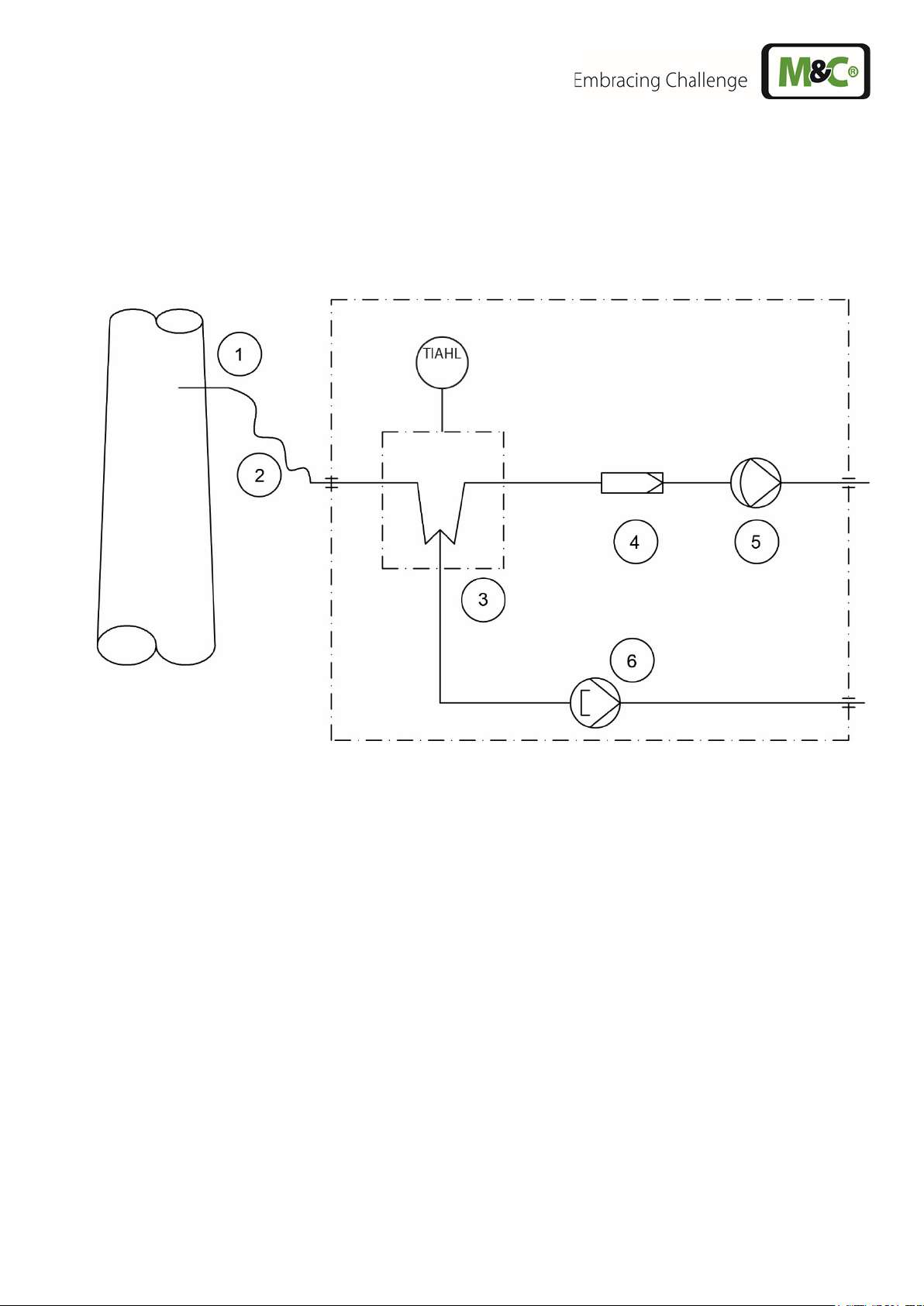
8 Application
The PSS-5C gas conditioning system is suitable for variable discontinuous use as well as for
continuous operation.
The upright, closed PSS-5C case with screwed in connectors complies with protection class IP42 as
required by the EN15267-4:2017 standard. It contains a standard gas temperature monitoring as well
as a temperature display visible from the outside.
Gas sample probe made of SS316Ti, Ø 4/6 mm, length 0.5 m
Gas sample line, PVC tube, Ø 4/6 mm, length 3 m
Peltier gas cooler with temperature alarm high/low (TIAHL)
Fine filter FP-2T, filter element porosity 2 µm
Sample gas pump N3 KPE (options: N5 KPE (Part No. 01G9090), N9 KPE (Part No. 01G9095))
Peristaltic pump SR25.2-W for continuous condensate removal
Figure 5 Gas flow diagram of PSS-5C and PSS-5/3C
www.mc-techgroup.com PSS-5C | 1.02.02 11
Page 12
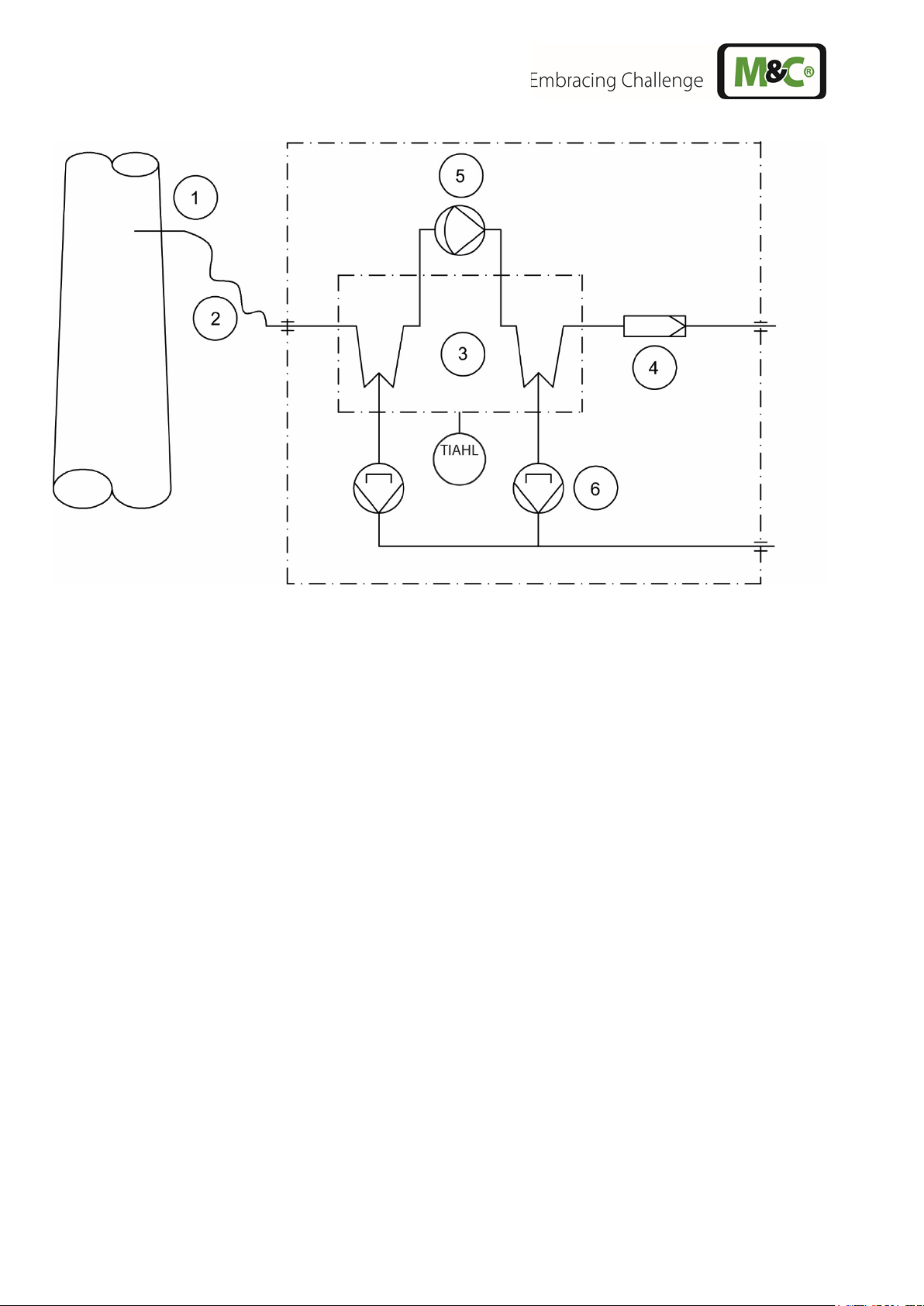
Gas sample probe made of SS316Ti, Ø 4/6 mm, length 0.5 m
Gas sample line, PVC tube, Ø 4/6 mm, length 3 m
Peltier gas cooler with temperature alarm high/low (TIAHL)
Fine filter FP-2T, filter element porosity 2 µm
Sample gas pump N3 KPE (options: N5 KPE (Part No. 01G9090), N9 KPE (Part No. 01G9095))
Peristaltic pump2 2 x SR25.2-W for continuous condensate removal
Figure 6 Gas flow diagram of PSS-5/2C
12 PSS-5C | 1.02.02 www.mc-techgroup.com
Page 13

9 Technical data
Gas Conditioning Type
PSS-5C
PSS-5/2C
PSS-5/3C
Part No.
01G4000
01G4250
01G4500
Sample gas outlet dew point
Range of adjustment: +2 to 15 °C [35.6 to 59 °F], factory setting:
ew point
stability
Sample gas inlet temperature
*Max. 80°C [176 °F], optional: *max. 180°C [356 °F] with stainless
Sample gas inlet water vapor
*Max. +80 °C [176 °F]
Heat exchanger gas flow rate
*Max. 150 Nl/h
*Max. 150 Nl/h per
*Max. 350 Nl/h
Ambient temperature
*5 to 40 °C [41 to 104 °F]
Storage temperature
-25 to +65 °C [-13 to +149 °F]
Pressure
0.7 bar to 1.4 bar abs.
Total cooling power*
Max. 80 kJ/h
Number of gas inlets
1
Medium connections
Tube connections 4/6 mm
Material of parts beeing in
Stainless steel, glass, PVDF, PTFE, Novoprene®
Ready for operation
Approx. 3 min. (with heated line approx. 1 h)
Mains power supply
115 or 230 V AC ±10 % 50/60 Hz
Power consumption
Max. 240 VA; with option temperature controller and heated
Fuse protection
4 A t, 5 mm x 20 mm; with option temperature controller: 10 A t,
Electrical connection
2 m [≈ 6.56 ft] length cable
Electrical equipment standard
EN 61010
IP42 EN 60529, with upright case and door closed. Unused
Housing
Portable impact-resistant case with integrated trolley system and
Housing color
Black
Housing dimensions
451 x 654 x 279 mm [≈ 17.8“ x 25.7“ x 11“] with casters and handle
Weight
Approx. 17 kg [≈ 37.5 lbs]
Sample gas outlet d
saturation
+5 °C [41 °F]
At const. conditions: < ±0.1°C [±0.18 °F]
steel bulkhead union
heat exchanger
Number of gas outlets 1, optional: max. 2
contact with the medium
sample line: 230 V, max. 1620 VA; 115 V, max. 920 VA
5 mm x 20 mm
Case protection
connectors must be closed with appropriate caps.
pull-out handle
(W x H x D)
PTFE=Polytetrafluoroethylene (Teflon®), PVDF=Polyvinylidenfluoride
* Maximum values in technical data must be rated in consideration of total cooling capacity at 25 °C [77 °F] ambient
temperature and an outlet dew point of 5 °C [41 °F].
www.mc-techgroup.com PSS-5C | 1.02.02 13
Page 14
Options
Type
Part No.
Sample tube
Sample tube out of Kanthal® ø 6 mm, length: 1 m, sampling
temperature: max. 1300 °C [2372 °F]
01G9030
Electronic
heated sample line
100 W/m
701 control range: 0 to 200 °C [32 to 392 °F], inlet PT100, power:
01G9055
Electronic tempera-
sample line 100 W/m
701 control range 0 to 200 °C [32 to 392 °F], inlet PT100, power:
01G9055a
Connecting adapter
PSS-5C connecting adapter with anti-kink protection for rigid
sleeve, material: SS316Ti
01G9060
Connecting adapter
DN 6/8 for heated
PSS-5C connecting adapter with anti-kink protection for rigid
sleeve, material: SS316Ti
01G9061
Sample gas pump
N5 KPE, replacement
Extra charge for replacing the standard N3 KPE by the N5 KPE
01G9090
Sample gas pump
N9 KPE, replacement
Extra charge for replacing the standard N3 KPE by the N9 KPE
01G9095
Flow meter including
FM40 7-70 Nl/h air
01G9072
temperature controller
for max. 12 m [39.4 ft]
ture controller for max.
6 m [19.7 ft] heated
DN 4/6 for heated
sample line
sample line
230 V/50 Hz, contact capacity: 250 V AC max. 10 A, completely
mounted incl.
7-pin plug 10 A
115 V/60 Hz, contact capacity: 250 V AC max. 10 A, completely
mounted incl.
7-pin plug 10 A
mounting of heated sample line with replaceable PTFE tube DN
4/6, consisting of special Swagelok fitting with 4 mm support
mounting of heated sample line with replaceable PTFE tube DN
6/8, consisting of special Swagelok fitting with 6 mm support
sample gas outlet,
max. 2 pieces
FM40 15-150 Nl/h air
FM40 25-250 Nl/h air
FM40 50-500 Nl/h air
01G9077
01G9082
01G9087
14 PSS-5C | 1.02.02 www.mc-techgroup.com
Page 15
Options
Type
Part No.
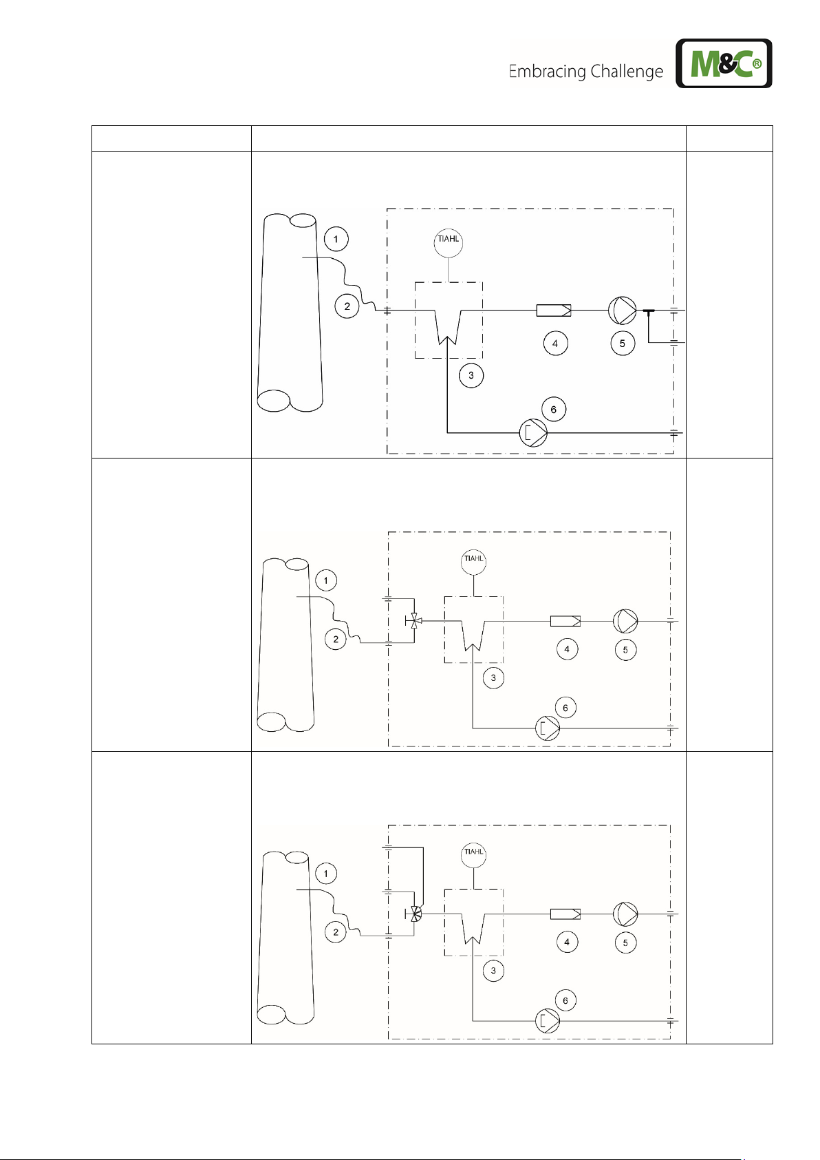
Further sample gas
Parallel sample gas outlet, tubing via T-piece on lateral PVDF
01G9065
3-way ball valve
(Note: only one FM40
flow meter is possible
3L/PV-1 for switching over from test gas to sample gas, in the
01G9046
5-way ball valve
(Note: only one FM40
flow meter is possible
5L/PV-1 for switching over from test gas to sample gas, in the
01G9045
outlet w/o flow meter
with this version)
bulkhead fitting, DN 4/6, max. 1 piece
inlet of the sample gas conditioning unit, mounted with mounting
bracket, fittings in PVDF
inlet of the sample gas conditioning unit, mounted with mounting
bracket, fittings in PVDF
with this version)
www.mc-techgroup.com PSS-5C | 1.02.02 15
Page 16

Options
Type
Part No.
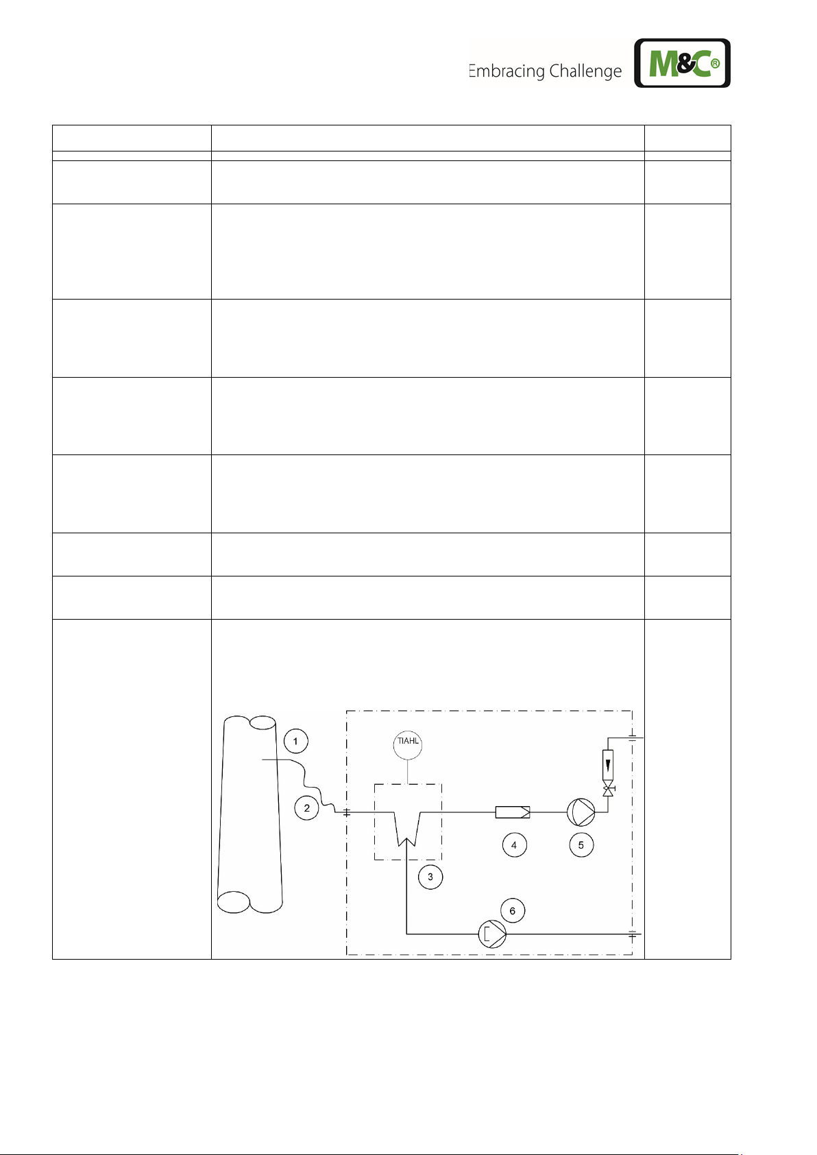
Needle valve
Needle valve in the bypass of the sample gas pump type
N3/N5/N9 for pressureless control, with PVDF screw
connections, mounting bracket and assembly
01G9050
Analog output
Analog output of the sample gas cooler temperature at the PSS-
5C 0/4 to
01G9010
mA output
Thermocouple type K for temperature measurement in heat
load 100 Ohm
01K9250
Liquid alarm sensor
Liquid alarm detection inside the PSS-5C case incl. switch-off
pump, liquid sensor type LA1S, for
01G9015
5C case with connection socket, mA output for PSS20 mA, galvanically isolated, burden: 500 Ohm
exchanger with output 4-20 mA for -10 to 50 °C [14 to 122 °F],
LA1S
function for sample gas
conductive media, completely wired, evaluation via front display
16 PSS-5C | 1.02.02 www.mc-techgroup.com
Page 17

Options
Type
Part No.
SR25.3-W
For acid dosing by an additional peristaltic pump.
01P1320
(Note: only one FM40
flow meter is possible
with this version)
Other versions on request.
www.mc-techgroup.com PSS-5C | 1.02.02 17
Page 18

10 Dimensions
Figure 7 Dimensions
11 Description
The PSS-5C gas conditioning system is equipped with the powerful Peltier gas cooler of the new
series as standard.
The cooler is equipped with a jet-stream heat exchanger, which cools the sample gas constantly to
+5 °C [41 °F], independent of the ambient temperature. As soon as the operating temperature
< +8 °C [46.4 °F] is reached after commissioning, the sample gas pump N...KPE is automatically
switched on by the gas cooler status contact. The peristaltic pump SR 25.2-W ensures continuous
condensate removal. This also allows to easily accomplish long-term measurements with the gas
conditioning system. The corresponding particle filtration is carried out by the FP-2T fine filter.
For easy handling of the PSS-5C, the display and function of the cooler are visible from the outside.
The case only needs to be opened for maintenance.
The portable PSS-5C gas conditioning system is a complete conditioning system for most gas
analysis devices. The components installed in the PSS-5C are intended for “continuous use”.
For special measuring tasks, additional or other components from our extensive product range can
also be used.
18 PSS-5C | 1.02.02 www.mc-techgroup.com
Page 19

1 Case door with display
5 Sample gas pump
2 Case
6 Peristaltic pump
3 Terminal mounting rail
7 Gas coolerr
4 Fine filter FP-2T
8 Heat exchanger
4
5
6
7
8
3
1 2
Figure 8 Case content: PSS-5C and PSS-5/3C
All components of the gas conditioning system are freely accessible and built into a portable case 2.
The case door 1 can be opened to the left by loosening the latches mounted on the side and top of the
case.
The installation of the gas cooler 7 and a corresponding diaphragm sample gas pump 5 depends on the
required maximum gas volume flow.
The minimum flow rate is determined by the sample gas pump 5. If the required minimum total flow rate
is not reached, excessive overpressure can lead to premature destruction of the pump diaphragm. The
maximum pressure is reduced by using an optional needle valve in the bypass of the sample gas pump
(Part No. 01G9050).
The gas cooler is equipped with a Duran glass heat exchanger 8 as standard. Heat exchangers in PVDF
or stainless steel are optionally available.
The FP-2T fine filter (2 µm filter porosity) 4, installed upstream of the sample gas pump 5, ensures the
necessary solids separation.
The overtemperature alarm contact (+8 °C [46.4 °F]) of the cooler automatically regulates the
switching on and off of the sample gas pump 5.
The resulting condensate is continuously discharged by a peristaltic pump type SR25.2-W 6.
www.mc-techgroup.com PSS-5C | 1.02.02 19
Page 20

The 4/6 mm tube connections for the condensate and sample gas lines are located on the side of the
case.
A stainless steel sample probe (length 0.5 m, Ø 6 mm) and a 3 m PVC sample tube (4/6 mm) are
included in the standard scope of delivery.
The ventilation grids in the door and in the left side wall of the case provide sufficient convex forced
ventilation.
Options:
The PSS-5... sample gas conditioning unit can be equipped at the factory with a maximum of two
sample gas outlets. Each sample gas outlet can be controlled by the optional installation of a flow
meter type FM40 with needle valve according to the specified volume flow range (see the option table
in chapter ‘9 Technical data’).
Unused mounting holes for sample gas outlets or flow meters are closed with blind caps.
I To protect the downstream analyzers against liquid ingress and to increase the operational reliability
of the entire system, we recommend the installation of a liquid alarm sensor type LA1S (Part No.
01G9015). For this purpose, the FP-2T fine filter installed as standard is replaced by the FP-2T-D fine
filter with mounted liquid alarm sensor at the factory. The evaluation electronics for the LA1S liquid
sensor are integrated as standard in the ECPX000C cooler.
The PSS-5... can also be equipped with a special sample gas inlet (Part No. 01G9060) for connecting
a heated line. The existing kink protection can only be used for heated lines with connection type "C"
(Part No. 03B1012). Assembly instructions can be found in chapter “18.1.1 Connecting the heated
sample line with special adapter (option)”.
It is also possible to connect the heated line (Part No. 01B4036) in connection with the gas sampling
probe PSP 4000.
The temperature controller 701 (Part No. 01G9055) which is necessary for the regulation of the heated
line is mounted on the terminal rail 3 (Figure 8) at the factory with the required option.
A 3-way ball valve (Part No. 01G9046) or a 5-way ball valve (Part No. 01G9045) can optionally be
installed in the inlet of the gas conditioning unit for test gas feeding or sample gas switching.
20 PSS-5C | 1.02.02 www.mc-techgroup.com
Page 21

12 Operating instructions
NOTE
The complete instruction manual of the ECPX000C can be found at
Use the arrow keys to navigate through the menu and
The display and control panel of the ECPX000C are clearly visible on the front panel of the device.
The functions described here are excerpts from the operating instructions of the ECPX000C series. For
the complete documentation, read the ECPX000C instruction manual.
It can be downloaded free of charge from the M&C homepage.
www.mc-techgroup.com.
In the main menu, the cooler temperature, the ambient temperature, the set absolute or differential set
point and the current set point can be displayed. The set point entry and the menu for parameter
setting can be accessed via a PIN entry. PIN entry prevents unintentional adjustment of the set point
and the device configuration.
enter values. Press the "OK" key to confirm entries
and the "Exit" key to exit the input area or to reject an
entry.
12.1 Main Menu
After approx. 3 minutes the device is ready for operation. The current cooler temperature is displayed
first. Use the arrow keys to navigate through the main menu. The following figure shows an example of
how you can navigate through the main menu.
Figure 9 Navigating through the main menu
www.mc-techgroup.com PSS-5C | 1.02.02 21
Page 22

NOTE
Tap on the -key, to go back to the cooling temperature.
The cooler temperature is shown on the display.
The ambient temperature is indicated by a "°" sign on the left side of
The set point for absolute value control is indicated by an "A" and the
The display of the current signal value is indicated by a capital "P" on
NOTE
The PIN “1234“ looks like this on the display.
The cooling temperature is shown in the display as follows:
the displayed temperature.
set point for differential control by a small "d" before the temperature
value.
The absolute value control temperature can be set between 2 to
15 °C [35.6 to 59 °F]. The differential value control temperature can
be set between dT = 2 to 15 °C [dT = 3.6 to 27 °F].
the right-hand side. The signal value is a measure for the percentage
workload. The signal value can assume values from 0 to 99.
You will find the complete menu structure in the appendix of the
ECPX000C instruction manual.
12.2 PIN Entry
To enter the range of set point input or parameter setting, a PIN must be entered. The PIN "1234" is
factory-set and cannot be changed.
To enter the PIN, proceed as follows:
Press and hold the -key until "0000" appears in the display.
The "0" on the left side is blinking. Use the and - keys to enter
the first digit of the PIN.
Use the and - keys to switch to the other digits. If a digit is
blinking, the PIN digit can be entered.
Confirm the PIN with the -key.
22 PSS-5C | 1.02.02 www.mc-techgroup.com
Page 23

After confirmation, immediately the display for the set point entry is shown. Press and hold the -key
NOTE
2 s
2 s
longer to access the parameter setting area.
The PIN is valid for 15 minutes. If you exceed this time, the display field reappears with "0000" when
you press and hold the
-key. The PIN must be entered there again.
12.3 Set Point Entry
If you tap the -key briefly after entering the PIN (see chapter “12.2 PIN Entry”), the set point for the
cooler temperature appears. This set point can belong to the operating mode "absolute control" ("A")
or "differential control" ("d").
The two digits start blinking. The absolute value control temperature can be set from 2 to 15 °C [35.6
to 59 °F] using the and -keys. The differential value control temperature can be set from dT = 2
to 15 °C [dT = 3.6 to 27 °F] using the and -keys. The factory setting is absolute value control
temperature of 5 °C [41 °C].
Use the and -keys to switch between the operating mode and
set point settings.
If the letter on the left side is blinking, you can use the and
-keys to switch between absolute and differential value control of
the set point temperature.
Tap the -key, then the entries are discarded and you return to the
cooler temperature.
As long as the PIN is active (see chapter “12.2 PIN Entry”), the set point entry can also be accessed
from the main menu. To change a set point, press the -
key for 2 seconds during the current
temperature or set point display. The display then changes to set point input. The two digits start
blinking. Values can be set here.
The following figure shows, using the example of an ECP1000C/ECP3000C, how to access the set
point input from the main menu.
Figure 10 Reaching the set point entry from the ECP1000C/ECP3000C main menu
www.mc-techgroup.com PSS-5C | 1.02.02 23
Page 24

13 Parameter Setting
NOTE
The codes for parameter settings can be found in the appendix of this
To adjust the device parameters, the code belonging to the
-keys to set the individual digits.
If you tap the -key after entering the PIN (see chapter “12.2 PIN Entry”), the set point for the cooler
temperature appears first. If the -key is pressed and held for a short moment, the display changes
to code entry. Here you can enter the codes that belong to the respective parameter settings.
You can also access the parameter setting from the main menu. To do this, keep the -key pressed
until the code entry is displayed. The PIN must be active in this case.
instruction manual.
parameter must be entered and confirmed in this display. The left
digit of the code entry is blinking. The first digit can be entered here.
Use the und -keys to switch between the digits and the and
A code can have up to 3 digits. Single-digit codes are device-specific, two-digit codes are important
basic settings (tens digit corresponds to the channel number), three-digit codes are used for
calibration (hundreds digit: "2" stands for LA, "3" for mA calibration).
The PIN is valid for 15 minutes. If you exceed this time, the display field reappears with "0000" when
you press and hold the -key. The PIN must be entered there again (see chapter “12.2 PIN Entry”).
If you enter an invalid code and press the -key, the display returns to the cooler temperature.
24 PSS-5C | 1.02.02 www.mc-techgroup.com
Page 25

13.1 Setting Temperature Alarm Limits
The code for setting HIGH dT of the channel is "012". Confirm the
After confirming the code, the default value "3" appears. The value is
shows the cooler temperature again.
NOTE
If HIGH dT or LOW dT is reduced to “2”, the hysteresis is
t
T
Cooler
HIGH dT = 3 °C
5 °C
3 °C
8 °C
hysteresis = 1
hysteresis = 1
no alarm
lower temperature alarm limit
set
value
upper temperature alarm limit
alarm
alarm
no alarm
LOW dT = 2 °C
You use the temperature alarm limits to determine when the alarm is triggered. HIGH dT and LOW dT
are independently adjustable from dT = 2 to 8 °C [dT = 3.6 to 14.4 °F]. In the following figure, the
upper temperature alarm limit is set at 8 °C [46.4 °F] and the lower one at 3 °C [37.4 °F].
The hysteresis is set to "1".
Figure 11 Temperature alarm limits and hysteresis
To set the temperature limits:
1. Enter the PIN (see chapter “12.2 PIN Entry”).
2. Tap and hold the -key for a short moment.
3. The display shows the code entry.
code with the -key, then the display of the pre-set value appears.
blinking and you can enter values from dT = 2 to 8 °C [dT = 3.6 to
The code for setting LOW dT is "013". If you enter this code, you can change the lower temperature
alarm limit.
The hysteresis setting can be changed via code "014". The hysteresis ensures that no “fluttering”
occurs in the event of a temperature alarm. The differential value dT = 1 or 2 °C [1.8 or 3.6 °F] can be
entered.
14.4 °F] with the and -keys.
Press to confirm your change or to leave the code range
without making any changes. After changing or aborting the display
www.mc-techgroup.com PSS-5C | 1.02.02 25
automatically reduced to the differential value dT = 1 °C [1.8 °F].
Page 26

13.2 Fan Speed Setting
Now the default brightness value appears. The factory setting is "5".
The ECPX000C is equipped with a large cooling fin block which is forced-ventilated by a fan. The
minimum speed of the fan can be changed without affecting the final performance of the cooler.
To change the fan speed setting:
1. Enter the PIN (see chapter “12.2 PIN Entry”).
2. Tap and hold the -key for a short moment.
3. The display shows the code entry.
4. The code for setting the fan speed is "084". The setting range is between 0 and 5. At level 0
the fan rotates slower and is quieter. At higher values, the fan rotates faster and the air flow
rate is increased.
Level 2 is set by default This fan speed is necessary to reduce the temperature increase inside the
case.
13.3 Brightness Setting of Display
It may be necessary to change the brightness of the display due to different lighting conditions at the
locations where the cooler is used. The brightness of the display can be adjusted on the control panel
of the ECPX000C.
To change the brightness setting:
1. Enter the PIN (see chapter “12.2 PIN Entry”).
2. Tap and hold the -key for a short moment.
3. The display shows the code entry.
You can also enter the code from the main menu. To do this, keep the --key pressed until the code
entry is displayed. The PIN must be active in this case.
Enter the code "005" and confirm the code with the --key.
This value is blinking and can be set between "0" and "9" with the
and - keys. The brightness of the digits changes immediately. The
lower the value, the darker the display.
Select the desired brightness value and confirm the selection with
the -key or cancel the procedure with the key. Use the -key to
leave the range of codes without making any changes.
After changing the brightness or canceling, the display shows the cooler temperature again.
26 PSS-5C | 1.02.02 www.mc-techgroup.com
Page 27

14 mA Output for the Temperature Measurement inside the Cooling Block
key, then the
The default value "4-20", which stands for 4 to 20 mA, appears on the
If the mA output is ordered when ordering the instrument, the mA
customer and retrofitted by the customer, the calibration must be
to the temperature range -10 °C to +50 °C [14 to 122 °F].
The mA outputs built-in by M&C are factory calibrated and set to the range "4-20 mA". Later purchased
mA outputs must be calibrated.
14.1 mA Output Range Selection
The optional mA output can be changed from 4-20 mA to 0-20 mA. To select the mA range, proceed as
follows:
1. Enter the PIN (see chapter “12.2 PIN Entry”).
2. Tap and hold the -key for a short moment.
3. The display shows the code entry.
Enter the code "015". Confirm the code with the display of the preset range appears.
display. The whole display is blinking here. Use the and -keys
to switch between "4-20" and "0-20".
Press to confirm your change or to leave the code range without
making any changes. After changing or aborting the display shows the
cooler temperature again.
14.2 mA Output Calibration for the Temperature Measurement inside the Cooling Block
The mA output built-in by M&C are factory calibrated. If required, the basic accuracy of the mA output
can be optimized by recalibration.
A later installed mA output must be calibrated. The mA output is suitable for a maximum load of 500 Ω
only.
During calibration, first the lower and then the upper value of the mA output will be calibrated.
output is calibrated at the factory. If a mA output is purchased by the
NOTE
carried out by the customer.
Optionally, the device can be sent to M&C for retrofitting.
The mA output is set to 4 - 20 mA as standard, but can be changed to
0 - 20 mA on the instrument. In both cases the mA range corresponds
Current limitation:
The current output limits in the case of 4 - 20 mA in the lower range to 3.8 mA and in the upper range
to 20.5 mA.
In the case of 0 - 20 mA, it limits the upper range to 20.5 mA.
www.mc-techgroup.com PSS-5C | 1.02.02 27
Page 28

If a calibration error occurs and the mA output has been calibrated, the
limiting values also change!
Enter the code "310" for the calibration of the lower value of the mA
1 mA as
Enter the code "C311" for the calibration of the upper value of the mA
possible. Accept the value with the -key.
NOTE
To calibrate an mA output, proceed as follows:
1. Enter the PIN (see chapter “12.2 PIN Entry”).
2. Tap and hold the -key for a short moment.
3. The display shows the code entry.
output.
Now connect a current meter to the connector of the mA output. This
current meter should measure a value close to 1 mA. You can now
adjust this value in 0.0054 mA steps with the up and down arrow keys.
After the adjustment, the current meter should display
accurately as possible. Accept the value with the -key.
output.
Now connect a current meter to the connector of the mA output. This
current meter should be used to measure a value close to 20 mA. You
can now adjust this value in 0.0054 mA steps with the up and down
arrow keys until the current meter displays 20 mA as accurately as
The cooler should then be in a steady state at 5 °C [41 °F] (absolute value control) and provide one of
the following values:
• 8 mA (in case of 4 - 20 mA)
• 5 mA (in case of 0 - 20 mA)
The cable length is not limited and the cable does not need to be shielded.
28 PSS-5C | 1.02.02 www.mc-techgroup.com
Page 29

15 Liquid Alarm Sensor (LA) type LA1S
The code for activation is "010".
You can choose between the values "0", "1" and "2". With "1" you
he sensor is
deactivated accordingly.
The liquid alarm sensors LA1S installed by M&C are factory calibrated to tap water and activated. Later
purchased liquid alarm sensors must be activated and calibrated.
15.1 Activating the LA
A retrofit liquid alarm sensor must be activated.
To activate a liquid alarm sensor:
1. Enter the PIN (see chapter “12.2 PIN Entry”).
2. Tap and hold the -key for a short moment.
3. The display shows the code entry.
Confirm the code with the -key.
activate the sensor without cable break detection, with "2" you activate
the sensor with cable break detection. With "0" t
After activating the LA1S, the sensor needs to be calibrated.
www.mc-techgroup.com PSS-5C | 1.02.02 29
Page 30

15.2 LA Sensitivity adjustment
Enter the code "011" to change the sensitivity of the liquid sensor.
Sensor state
Sensitivity
Electrical conductivity
Dry
0 %
7
30 %
≈50 µS/cm
6
40 %
5 50 %
4 60 %
3 70 %
2
80 % (Standard)
≈300 µS/cm
1
90 %
Wet
100 %
W
et (100 %)
1
2
3
4
5
6
7
Dry (0 %)
Alarm limit for
cable b reak and
can celation
Open
LA cable break
alarm is canceled
LA cable break
alarm is actived
LA alarm at
default setting 2
Canceled: LA alarm at
default setting 2
2. Cancelation
t
LAvalue
The sensitivity can be changed by following these steps:
1. Enter the PIN (see chapter “12.2 PIN Entry”).
2. Tap and hold the -key for a short moment.
3. The display shows the code entry.
The default value is 2 and can be changed from 1 to 7. The sensitivity corresponds to the switching
threshold for the alarm and is to be understood as follows:
The cancellation limit is always 15 % below the sensitivity limit. If the sensitivity value of 2 is not changed,
the alarm is triggered at 80 % and is automatically cancelled as soon as it falls below 65 %.
The following diagram illustrates the correlations:
Figure 12 LA alarm limits
30 PSS-5C | 1.02.02 www.mc-techgroup.com
Page 31

15.3 LA Calibration
First calibrate the "dry state" of the liquid alarm sensor.
To do this, leave the LA in the dry state and enter the code "210".
Then calibrate the "wet state" of the liquid alarm sensor.
The liquid alarm sensors LA1S installed by M&C are factory activated and calibrated. If required, the
basic accuracy of the liquid alarm sensors can be optimized by recalibration. Later-installed liquid
sensors must be activated and calibrated.
Make sure that the LA is activated. If a retrofitted LA is not activated,
the calibration has no effect and will be discarded.
NOTE
To calibrate a liquid alarm sensor, proceed as follows:
1. Enter the PIN (see chapter “12.2 PIN Entry”).
2. Tap and hold the -key for a short moment.
3. The display shows the code entry.
Confirm the displayed value with the -key.
Immerse the LA in the process-dependent condensate to calibrate the
100 % wet condition via code "211". Confirm the displayed value with
the -key.
www.mc-techgroup.com PSS-5C | 1.02.02 31
Page 32

16 Receipt of goods and storage
The gas conditioning and sampling systems PSS-5C, PSS5/2C and PSS5/3C are completely preinstalled units.
The sample tube, gas sample hose, connecting cable and instruction manual are located inside the
case door.
• Immediately after arrival take the gas conditioning system and possible special accessories
carefully out of the packaging material.
• Compare the goods with the items listed on the delivery note.
• Check the goods for any damage caused during delivery and, if necessary, notify your transport
insurance company without delay of any damage discovered.
The gas conditioning unit should be stored in a protected
NOTE
frost-free area!
32 PSS-5C | 1.02.02 www.mc-techgroup.com
Page 33

17 Installation instructions
The case should be placed on a level, horizontal surface so that
Unheated gas sampling lines must be routed with a downward
separation is then not
necessary.
it is secure and stable.
NOTE
The operating position is exclusively upright. This is the only
way to ensure proper separation and removal of the condensate
in the cooler's heat exchanger.
The gas conditioning unit should be installed away from heat
sources and freely ventilated so that no disturbing heat
accumulation occurs
For outdoor installation, adequate protection against direct
sunlight and moisture must be provided. In winter, the
installation site must be frost-free; observe the protection class
of the case.
The device must only be operated upright and with the door
closed. Unused connectors must be closed with the appropriate
covers. IP42 means protection against foreign bodies ≥1 mm and
dripping water up to an angle of ≤ 15°.
In order to ensure the operational safety of the portable gas
conditioning system and the downstream analyzers and to avoid
false alarms, the sample gas conditioning system must not be
used outside the specified temperature range.
Downstream analyzers must always be operated at temperatures
well above the specified gas output dew point of +5°C [41 °F].
The temperature of the sample gas must not exceed the
specified temperature range. This avoids subsequent
condensation of the gas in the connecting lines to the analyzers.
gradient to the cooler. Condensate pre-
www.mc-techgroup.com PSS-5C | 1.02.02 33
Page 34

18 Supply connections
ections are marked
After all lines have been connected, the tightness must be
checked.
1 Sample gas IN
5 Connections description
2 Power supply
6 Type plate
3 Heated sample line connection
7 mA-output (temperature)
4 Condensate outlet
8 Flow meter(s) with sample gas OUT
18.1 Tube connections
Do not switch tube connections; conn
accordingly.
NOTE
Figure 13 shows the possible medium connections. These are located in the right-hand side of the
gas conditioning case at the rear in a specially immersed assembly frame.
Figure 13 PSS-5C and PSS-5/3C medium connections
All tube connections are equipped with 4/6 mm clamping ring tube fittings made of
polyvinylidenfluoride (PVDF) for gas inlet temperatures of up to a maximum of 80 °C [176 °F] (see
chapter ‘9 Technical data’). When heated sample lines are used, the gas inlet temperatures can
increase up to a maximum of 180 °C [356 °F]. In this case, the use of optional stainless steel bulkhead
fittings is recommended.
Connecting tubes of dimension 4/6 mm are used as standard.
34 PSS-5C | 1.02.02 www.mc-techgroup.com
Page 35

Install the sample gas tubes and the condensate tube as follows:
NOTE
The tightness of the connections can only be guaranteed if the
• Remove the union nut from the clamping ring tube fittings by turning it anti-clockwise. The nut
should be removed from the thread with great care so as to ensure that the loose sealing ring in
the nut is not lost.
• Place the union nut over the connecting tube.
• Place the sealing ring over the connecting tube with the thicker bead towards the nut.
• Place the tube over the nipple on the thread.
connecting tube has a straight rim (hose cutter).
• Tighten the union nut hand-tight.
The tube will no longer be able to slip off, and is now compression-proof.
Disassemble the tubes in reverse order.
WARNING
Aggressive condensate possible.
Wear protective glasses and proper protective clothing!
www.mc-techgroup.com PSS-5C | 1.02.02 35
Page 36

18.1.1 Connecting the heated sample line with special adapter (option)
mage the equipment. When
the supply voltage is
For the erection of power installations with rated voltages up to
The main circuit is equipped with a fuse corresponding to the
technical data.
Sample gas IN
Bulkhead union
Back ferrule 6mm Øi
Back ferrule
10mm Øi
Sealing ring
10mm Øi
Sealing ring
6mm Øi
support sleeve
4mm ØOD
Union nut 10mm Øi
Heated sample line
Adapter
PSS...
Figure 14 Connecting the heated sample line with special adapter (option)
The heated line is connected to the gas conditioning with the connection adapter (Part No. 01G9060)
as follows:
• Place the special adapter (Part No. 01G9060) on the PTFE tube according to the drawing seen
above;
• Place the support sleeve into the PTFE tube;
• Insert the PTFE tube as far as it will go into the 'Sample Gas IN' bulkhead fitting and hand-tighten
the adapter;
• Tighten the adapter 1 1/4 turns with a wrench (SW 14), while holding the lock nut of the bulkhead
connection with a wrench (SW 15);
• Insert the 10 mm tube of the heating line into the adapter as far as it will go and hand-tighten it with
the union nut;
• Tighten union nut with wrench (SW 19) 1 1/4 turns; hold adapter with wrench against;
The screw connection is now cut gas-tight and can be loosened as often as required.
18.2 Electrical connections
Wrong supply voltage can da
WARNING
connecting the equipment, make sure that
identical with the information provided on the model type plate!
1000 V, the requirements of VDE 0100 and relevant standards and
NOTE
specifications must be observed!
nominal current (over current protection); for electrical details see
36 PSS-5C | 1.02.02 www.mc-techgroup.com
Page 37

The PSS-5... gas conditioning system is available with either 230 V/50 Hz or with 115 V/60 Hz (for
1 mA-output (temperature)
3 Heated sample line connection
2 Power supply connection
4 Connections description
circuit diagram see Appendix). The device is protected by a 4 A fuse as standard. The fuse is located
on the terminal mounting rail (see Figure 8). In the event that a temperature controller is used in
conjunction with heated sample lines, the overload protection level is increased to 10 A.
The power supply connector is a round 4 pole connector (male). The heated sample line connector
is a round 7 pole connector (female). The mA-output connector is a round 4 pole signal connector
(female). All electrical connectors are located on the left-hand side of the case.
Figure 15 Electrical connection
Option “heated sample line”:
For the electrical supply of a heated line with PT-100 sensor a 7-pin connector 3 is available. For the
electrical supply of other heated components (e.g. heated sample gas probe or heated filter) a 4-pole
round plug connector is available at the heated lines Part No 01B4050 or 01B4040. The maximum
connected load is 6 A, 1380 W for the 230 V sample gas conditioning unit and 6 A, 690 W for the 115 V
version.
The maximum length of a possible heated sample line is calculated as follows:
Max. connection power [W] - Power consumption of heated components (i.e. sample probe) [W]
L(m)=
Power consumption of heated sample line [W/m]
www.mc-techgroup.com PSS-5C | 1.02.02 37
Page 38

Option "mA output; cooling block temperature Part No 01G9010":
The connection of the mA signal output is a 4-pole circular connector (female) 1.
The mA output signal is available at pin 1 + and 3 -.
Measuring range: -10 to 50 °C [14 to 122 °F], mA output 4 to 20 mA or 0 to 20 mA, factory setting 420 mA. To select the mA output range and to calibrate the mA output see chapter 14.1 and 14.2.
The load is 500 Ohm.
Option "mA output; temperature in heat exchanger Part No 01K9250":
The connection of the mA signal output is a 4-pole circular connector (female) 1.
The output signal is available at pin 2 + and 4 -.
Measuring range -10 to 50 °C [14 to 122 °F], mA output 4 to 20 mA, load 100 Ohm.
The range of the mA output is fixed and can only be changed at the factory.
38 PSS-5C | 1.02.02 www.mc-techgroup.com
Page 39

19 Commissioning
temperature controller when
NOTE
The following minimum gas flow rates result from the requirement
side load of the sample gas pumps
Premature damage can be caused to the pump membrane if less
content in the
sample gas, a suitable gas sampling probe must be provided to
protect the sample line from being clogged.
Observe the facility and process-specific safety measures before commissioning.
Carry out the following steps before initial commissioning:
• Connect the round 4 pole connector (male) 2 on the device with the supplied mains connection
cable;
• Connect the heated sample line (option);
Check the temperature at the
operating the sample gas conditioning unit with a heated sample
WARNING
• Connect the mains plug of the supplied mains connection cable to the power supply;
• Set the desired temperature on the temperature controller.
Type 701:
The digital display of the controller shows the actual value of the heated line after switching on
the sample gas conditioning. The controller is factory set to 0 °C [32 °F]. Briefly press the P key to
change the set point. SP appears in the display and then the display changes to the adjusted set
point. Use the arrow keys to set the desired value. After 60 seconds, the display automatically
changes to the actual value.
gas line.
The complete instruction manual of the temperature controller
701 is available at www.mc-techgroup.com.
The gas cooler is ready for operation after approximately 3 minutes. If a heated line is connected, the
time in which the gas conditioning unit is ready for operation increases to approx. 1 hour.
The over temperature alarm contact of the cooler switches the sample gas pump automatically on as
soon as the temperature reaches +8 °C [46.4 °F].
of the maximum pressureN3 KPE, N5 KPE and N9-KPE of 1.4 bar abs:
NOTE
N3 KPE approximately 60 Nl/h air,
N5 KPE approximately 100 Nl/h air,
N9 KPE approximately 200 Nl/h air.
than the minimal total amount of flow is extracted as a result of over
pressure.
For long-term measurements with a high dust
www.mc-techgroup.com PSS-5C | 1.02.02 39
Page 40

20 Closing down
NOTE
The area where the gas conditioning unit is placed must remain
frost-free even when the unit is switched off.
No special measures are to be taken in the event of short-term shutdowns of the gas conditioning
system.
In the case of long-term shutdowns, for example after a completed series of measurements, it is
recommended to purge the gas conditioning system with fresh air or inert gas. A flushing time of 3 to
5 minutes is sufficient under normal conditions. Condensate residues must also be removed from the
system.
WARNING
Aggressive condensate is possible.
Wear protective glasses and proper protective clothing!
40 PSS-5C | 1.02.02 www.mc-techgroup.com
Page 41

21 Maintenance
NOTE
In order to protect downstream analyzers, the wet filter element
NOTE
NOTE
Observe the facility- and process-specific safety measures before carrying out maintenance work!
Dangerous voltage!
WARNING
It is necessary to take the equipment off the mains before any
assembly, maintenance or repair work is carried out.
The frequency of the maintenance work depends on the operational process and can therefore only
be determined in each individual case.
All parts which might require maintenance work are easily accessible housed in the gas conditioning
system. The following parts might require maintenance work (see Figure 8):
• Check the filter element of the fine filter FP-2T and replace if necessary.
must always be replaced in the event of a condensate
breakthrough.
• Check the tube of the SR25.2-W condensate pump every six months and replace if necessary;
The complete instruction manual of the SR25.2-W is available at
www.mc-techgroup.com.
• Check the diaphragm of the gas feed pump N3 KPE (optional N5 KPE or N9 KPE) every six months
and replace if necessary.;
The complete instruction manual of N3 KPE, N5 KPE, N9 KPE is
available at www.mc-techgroup.com..
• Check fan grids for contaminations and clean if necessary.
www.mc-techgroup.com PSS-5C | 1.02.02 41
Page 42

22 Trouble shooting
Problem
Display
Possible Causes
Check/Solution
No display
No voltage
Check supply voltage with model type plate;
Error code: E5
Cooler does not work;
Ambient temperature too high.
case
Diaphragm pump
Check voltage on terminals X2/17 and X2/8;
Contaminated
Remove the tubes at the pump head and check;
Sample probe/line
Remove sample line at gas inlet (see 1 in Figure 13);
Sample line to
Disconnect the outlet tube on the analyzer side and
Liquid alarm on
Optional liquid alarm
Momentary overloading of the cooler due to
of the peristaltic pump (see manual
(see manual
Current cooler
Optional flowmeter(s):
Adjust needle valve(s) to the desired flow
The following table aims to point out possible operational problems and offer solutions to such
problems (not applicable during the starting procedure).
OK?
Check if the supply voltage plug is insert correctly;
OK?
Check the fine fuse on connector block 3 (Figure 8);
OK?
Gas flow
interruption
Cooler alarm detects
‘over temperature’.
Cooler turns sample
gas pump off
automatically.
OK?
Free convection in case impaired
temperature too high;
OK?
Cooler error (see instruction manual ECPX000C);
ok?
does not work
diaphragm pump
Current cooler
tmperature(s)
Cooler works,
but gas flow is
interrupted
display: LA1
clogged up or sample
line squashed
analyzer clogged up
or squashed
sensor:
Sensor turns
measuring pump off
automatically;
ok?
OK?
Clean pump if necessary;
OK?
Gas flow?
Clean contaminated sample line or replace;
No gas flow?
check whether sample gas flows at the tube fitting;
No gas flow?
Clean contaminated lines or replace;
Gas flows?
excessive amount of condensate;
OK?
Check tubes for condensate removal;
OK?
Check tubes
peristaltic pump SR25.2-W);
OK?
Check peristaltic pump SR25.2-W
peristaltic pump SR25.2-W);
OK?
Check ECPX000C cooler instruction manual;
42 PSS-5C | 1.02.02 www.mc-techgroup.com
tmperature(s)
Needle valve closed.
Page 43

Problem
Display
Possible causes
Check/Solution
Cooler and
pump tube defect
Replace pump tube (see manual peristaltic pump
ok?
Peristaltic pump
Check peristaltic pump (see manual peristaltic pump
Unsufficient drying of
sample gas
Check ECPX000C (se ECPX000C cooler
instruction manual);
Sensor has not turned
off pump.
Check the LA sensor function
sample gas
pump
running;
Condensate
in the sample
gas line
Current cooler
tmperature(s)
SR25.2-W does not
work
SR25.2-W);
SR25.2-W);
ok?
www.mc-techgroup.com PSS-5C | 1.02.02 43
Page 44

23 Spare parts list
Portable Conditioning System PSS-5C, PSS-5/2C, PSS-5/3
recommended quantity
being in operation
[years]
Part No.
Description
C/R/S 1 2
3
Fine filter FP-2T:
90F0002
Filter element F-2T, PTFE, 2 µm
C 6 12
20
90F0040
Viton O-ring, 26 for FP-
R 1 1
1
90F0056
PVDF filter element clamp F-P
S - -
1
90F0012
Filter body F-120G of glass
R 1 1
1
Fine filter FP-2T with Option LA1S: 4 (see Figure 8)
90F0015
Filter body F-120G-D of glass
with GL 25 condensate connection thread
R 1 1
1
90F0020
Union nut GL 25
R 1 1
1
90F0025
PTFE sealing ring GL 25-12 mm Ø
R 1 1
1
Peristaltic pump SR25.2-W:
90P1007
SR25 pump hose with PVDF tube connectors
DN 4/6 mm
C 1 2
4
Diaphragm pump type N3 KPE/KP18; N5 KPE/KP18
90P2100
Square cap type D3, 1/8“i for N3/N5 KPE/KP18
Material: PVDF
S - -
1
90P2120
Diaphragm type S3, for N3/N5 KPE/KP18,
Material: Viton, PTFE coated
C 1 2
3
90P2115
Sealing ring type O3, for N3/N5 KPE/KP18,
1 piece, Material: Viton (2 pc. required)
C 2 4
6
90P2110
Valve plate type V3, for N3/N5 KPE/KP18,
1 piece, Material: Viton (2 pc. required)
C 2 4
6
90P2105
Intermediate plate type Z3, for N3/N5 PE/KP18
Material: PVDF
S - -
1
Diaphragm pump type N9 KPE/KP18
90P2200
Square cap type D9, 1/8“i for N9 KPE/KP18,
Material: PVDF
S - -
1
90P2220
Diaphragm type S9, for N9 KPE/KP18,
Material: Viton, PTFE coated
C 1 2
3
90P2211
Valve plate with seal for N9 KPE, 1 pc.,
material: Viton. (2 pcs./pump)
C 2 4
6
Wear, tear and replacement part requirements depend on specific operating conditions.
The recommended quantities are based on experience and are not binding.
For spare parts of components which are not presented in the following list please see the specific
instruction manuals or leaflets added in the appendix.
(C) consumable parts, (R) recommended spare parts, (S) spare parts
PSS-5...
44 PSS-5C | 1.02.02 www.mc-techgroup.com
Page 45

Portable Conditioning System PSS-5C, PSS-5/2C, PSS-5/3
(C) consumable parts, (R) recommended spare parts, (S) spare parts
recommended quantity
being in operation
[years]
Part No.
Description
C/R/S 1 2
3
90P2205
Intermediate plate type Z9, for N9 KPE/KP18,
S - -
1
Option flowmeter FM40:
90A0015
Flowmeter glass for FM40
range 7-70 l/h air
S - 1
1
94F0010
Flowmeter glass for FM40
range 15-150 l/h air
S - 1
1
94F0015
Flowmeter glass for FM40
range 25-250 l/h air
S - 1
1
94F0020
Flowmeter glass for FM40
range 50-500 l/h air
S - 1
1
90A0018
Viton O-ring 9 for flowmeter glass FM40
R 2 4
6
Diverse:
90K6030
Fine fuse 4 A T, 5 mm x 20 mm for PSS...
R 5 5
5
90G0020
Fine fuse 10 A T, 5 mm x 20 mm for PSS...
with option temp. controller and heated sample line
R 5 5
5
Hose and hose fittings:
05V3215
Bulkhead union SV-PVDF DN 4/6
PSS-5 optional PVDF = Polyvinylidenfluoride
R 2 2
2
05V6600
Sealing ring 4/6 PVDF
R 5 10
10
05V6605
Union nut M10-4/6 PVDF see above
R 5 10
10
01T4000
Tube PVC DN 4/6 (meters)
S 3 6
9
01T1000
Tube Viton DN 4/6 (meters)
S 1 2
3
01T2000
Tube Novoprene DN 3,2/6,4 (meters)
S 1 2
3
02B1000
Tube PTFE DN 4/6 (meters)
S 1 2
3
10T1000
Hose cutter
S 1 1
1
PSS-5...
Material: PVDF
see above
www.mc-techgroup.com PSS-5C | 1.02.02 45
Page 46

24 Appendix
• Circuit diagram PSS-5C
• Table of parameter codes
More product documentation is available in our Internet catalogue:
www.mc-techgroup.com
• Instruction manual: Electric gas cooler ECPX000C
• Data sheet: Universal-Filters FP, FT, FPK, FS, FSS
• Instruction manual: Diaphragm pump Series N
• Instruction manual: Peristaltic pump SR25.2-W
• Instruction manuals: Liquid alarm sensor LA1S and electronic controllers type LA1.4
• Data sheet: Flow meter FM40
• Data sheet : Ball valves L/PV-1
• Instruction manual: Temperature controller 701
46 PSS-5C | 1.02.02 www.mc-techgroup.com
Page 47

Figure 16 Circuit diagram PSS-5C
www.mc-techgroup.com PSS-5C | 1.02.02 47
Page 48

Table of Parameter Codes
No.
Description:
Default:
Range:
Note:
1
Software version
5
Brightness setting
of display
5
0 - 9
Brightest display setting is 9
10
LA on/off switching
0
0,1,2
0=off; 1= without cable break detection; 2= with
cable break detection
11
Sensitivity LA
2
1-7
The higher the value is, the sooner the alarm is
triggered.
12
HIGH dT
3
2 - 8
[°C]
Differential temperature between set point and
upper temperature alarm limit
13
LOW dT
3
2 - 8
[°C]
Differential temperature between setpoint and
lower temperature alarm limit
14
Hysteresis
alarm)
2
1,2 [°C]
As soon as a temperature alarm limit of "2" is
1
15
mA range
selection
4-20
0-20 / 420 [mA]
Corresponds to the temperature range: -10 °C to
+50 °C (4 – 20 mA: at 5 °C = 8 mA)
70
Operating time in
days
This value will not be deleted even after restarting
84
Fan speed
1
0-5
Value has no influence on the output power
210
Calibration LA dry
Connect the sensor and confirm with the -key.
211
Calibration LA wet
key.
212
Calibration LA
between this value and that of dry.
213
Display LA dry
Check here the current value
214
Display LA wet
Check here the current value
215
Display LA open
Check here the current value
310
mA output LOW
1 mA
-keys until the display matches 1mA.
311
mA output HIGH
20 mA
-keys until the display matches 20 mA.
(temperature
open / cable break
Calibration
Calibration
selected, the hysteresis is automatically reduced to
Hold the sensor in water and confirm with the -
Disconnect the sensor and confirm with the -key.
The cable break detection triggers in the middle
Connect the multimeter and press or hold or
Connect the multimeter and press and hold or
48 PSS-5C | 1.02.02 www.mc-techgroup.com
 Loading...