

Page 1
EC®
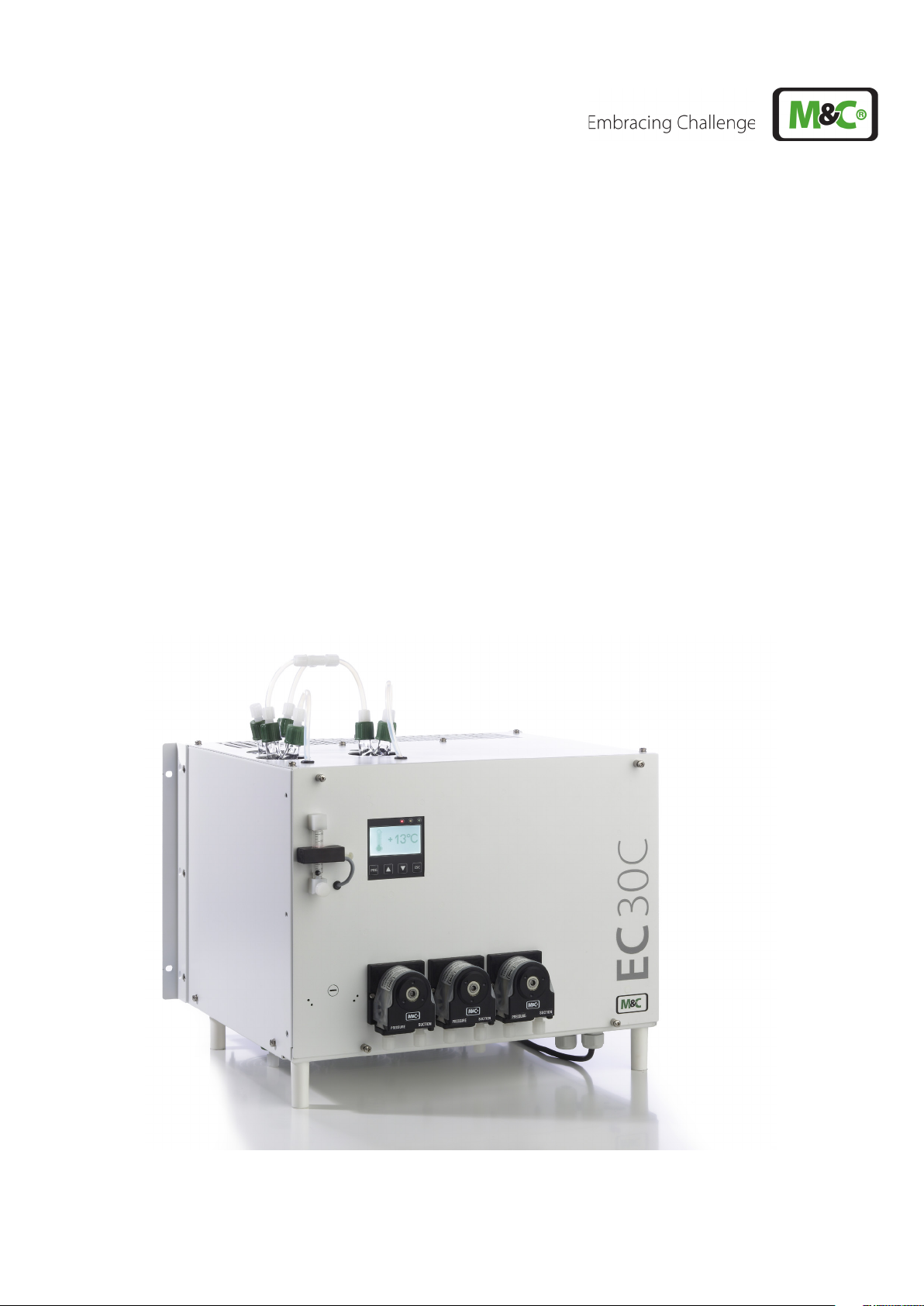
Ultra Low Gas Cooler
EC-30C
Instruction Manual
Version 1.00.02
Software Version 1.00
Page 2
Get help
For more information about using your M&C product, please contact
M&C TechGroup. We will answer your questions about commissioning,
handling and technical service. With our experience and know-how, we
will get your M&C product running in no time - and with no charge.
Please contact our service center in Ratingen, Germany,
for US Service Ventura, California
For faster service, please have this information ready when you contact
us:
Product model
Product serial number
M&C order or invoice number
Germany service center:
+49 2102 935 - 888
service-DE@mc-techgroup.com
US service:
+1 805-654-6970
info-usa@mc-techgroup.com
For online service and support information go to:
www.mc-techgroup.com
EC-30C | 1.00.02 +49 2102 935 888 www.mc-techgroup.com 1
Page 3
Table of Contents
1 About this instruction manual 6
2 Important safety information 7
2.1 Intended use 7
2.2 Personal safety 7
2.3 Warning signs and definitions 7
2.4 Safety instructions 8
2.5 Working on electrical and electronic devices 9
2.6 Not certified in hazardous areas 9
3 Introduction 10
4 Product overview 11
4.1 Application 11
4.2 Principle 12
5 Technical Data 14
5.1 Max. possible water vapor dew point input [°C] / [°F] 15
5.2 Dimensions 16
6 Receiving the EC-30C 17
6.1 Product label and serial number 17
7 Using the EC-30C 18
7.1 Graphical user interface (GUI) 18
7.2 LED color coding and possible color combinations 18
7.3 Self-monitoring after powering-on the unit 19
7.4 Self-monitoring during operation 20
7.4.1 Power consumption readjustment 20
7.4.2 Pre-warning messages 20
7.5 Display during start-up of the EC-30C 21
7.6 Overview screen 23
7.7 Alarm and warning history 24
7.7.1 Error codes 27
7.7.2 Warning symbols 27
7.7.3 Alarm symbols 29
7.8 Temperature diagrams 32
7.8.1 Diagram of the pre-cooler unit (PCU) 32
7.8.2 Diagram of the deep cooling units (DCU 1 and DCU 2) 33
7.9 Parameter menu 34
7.9.1 Parameter settings 36
7.10 Device information 37
7.11 Service-Reset (qualified personnel only) 39
2 EC-30C | 1.00.02 +49 2102 935 888 www.mc-techgroup.com
Page 4

8 Installation instructions and mounting of the EC-30C 40
8.1 Installation instructions 40
8.2 Wall and rack mount 41
8.3 Mounting instructions for SR25.2 peristaltic pump (optional) 43
8.4 Tubing without heat exchanger purging (standard tubing) 44
8.4.1 Heat exchanger connections for tubing without purging 44
8.5 Tubing with heat exchanger purging for special requirements (optional) 46
8.5.1 Heat exchanger connections for tubing with purging 47
8.6 Duran-glass heat exchanger with GL-connections 48
8.7 PVDF- heat exchanger with PVDF-tube connectors 48
8.8 Electrical connections 49
8.8.1 mA-output 51
8.8.2 Liquid alarm sensor LA (optional) 51
8.8.3 Gas flow sensor FA 20 and gas flow meter FM 40 (optional) 52
9 Start-up 53
9.1 Preparation for start-up 53
9.2 Temperature chart of the start-up stages 54
10 Maintenance 58
10.1 Maintenance of the peristaltic pump type SR25.2 (optional) 58
10.1.1 Changing the pump tubing 59
10.1.2 Changing the contact pulley and springs 60
10.1.3 Cleaning the pump head 60
10.2 Changing the heat exchanger 61
10.3 Changing the 0-20 V-Module 62
10.4 Changing the buffer battery 63
10.5 Checking the temperature sensors 64
10.6 Changing the compressor unit 65
11 Decommissioning 66
12 Appendix 67
12.1 Overview of the EC-30C screens 67
12.2 How to configure the mA-output 68
12.2.1 How to calculate temperature based on measured mA-value 68
12.2.2 How to calculate mA-value based on measured temperature 69
12.3 Spare parts and consumables 70
12.4 Additional Information 71
12.5 Declaration of conformity 71
12.6 Certificates 72
12.7 Warranty 72
12.8 Liability and disclaimer 72
12.9 Storage 73
12.10 Shipping and handling 73
12.11 Proper disposal of the device 73
EC-30C | 1.00.02 +49 2102 935 888 www.mc-techgroup.com 3
Page 5

13 About us 74
13.1 M&C‘s group of companies 74
13.2 The quality-oriented M&C catalog 75
13.3 Technical consulting services 76
13.3.1 Ideas, suggestions and feedback 76
4 EC-30C | 1.00.02 +49 2102 935 888 www.mc-techgroup.com
Page 6

Table of Illustrations
Fig. 1: Application example of the EC-30C 11
Fig. 2: Jet-Stream heat exchanger 12
Fig. 3: Front view: dimensions including optional peristaltic pumps 16
Fig. 4: Side view: dimensions including optional peristaltic pumps 16
Fig. 5: Graphic user interface 18
Fig. 6: Smiley symbols during self-test 19
Fig. 7: The smileys on the display after self-testing 19
Fig. 8: ‘Service‘-monitor: Self-test failed 20
Fig. 9: Start-up phase: first cooling phase 21
Fig. 10: Start-up phase: TKS reaches and/or exceeds ‘0 °C / 32 °F’-limit 22
Fig. 11: Start-up phase: Target temperature reached 22
Fig. 12: That’s how you reach the overview screen 23
Fig. 13: Overview screen 23
Fig. 14: How to reach the alarm and warning history 24
Fig. 15: Alarm and warning history 25
Fig. 16: How to chose an alarm or warning message 25
Fig. 17: How to scroll through stored messages 26
Fig. 18: Detailed information for a selected message 26
Fig. 19: How to reach the graphical temperature diagrams 32
Fig. 20: Temperature diagram of the pre-cooling unit 32
Fig. 21: Temperature diagram of the deep-cooling units 33
Fig. 22: How to reach the parameter menu (screen 1) 34
Fig. 23: Parameter menu, screen 1 34
Fig. 24: Parameter menu, screen 2 35
Fig. 25: How to reach the parameter settings 36
Fig. 26: How to reach the device information 37
Fig. 27: Device information 38
Fig. 28: Activating Service Reset (Qualified personnel only) 39
Fig. 29: Reset screen (Qualified personnel only) 39
Fig. 30: Min. assembly dimensions (unit with optional peristaltic pumps) 41
Fig. 31: Mounting rail for wall or rack mounting 42
Fig. 32: SR25.2: Mounting distance between pump motor and front panel 43
Fig. 33: Standard tubing: DCU 1 active, solenoid valve triggered, no FA 44
Fig. 34: Heat exchanger connectors (device with four optional peristaltic pumps) 45
Fig. 35: Tubing with purging: DCU 1 activ, solenoid valves triggered, no FA 46
Fig. 36: Heat exchanger connections, tubing with purging 47
Fig. 37: Electrical connections 50
Fig. 38: Temperature chart of the start-up stages 55
Fig. 39: Changing the pump tubing 59
Fig. 40: Resistor - temperature characteristic of the PT100 64
Fig. 41: Compressor: electrical connections 65
Fig. 42: Overview: screens 67
EC-30C | 1.00.02 +49 2102 935 888 www.mc-techgroup.com 5
Page 7

1 About this instruction manual
Welcome to the M&C product manual. The goal of this document is to give a broad overview of the main functions of the EC-30C. It will help you to get started with using the
EC-3 0 C .
If you have any questions about this instruction manual, please contact M&C or one of our
official distributors.
Document: Instruction Manual EN for EC-30C
Version: 1.00.02
Software Version: 1.00
Release date: 10.2019
Copyright: © 2019 M&C TechGroup
Published by: M&C TechGroup Germany GmbH, Rehhecke 79
40885 Ratingen, Deutschland
This instruction manual does not claim to be complete and it may be subject to technical
modifications. We appreciate any feedback you may have to this document .
Any copy of this document or of its content is not allowed without explicit approval of
M&C.
With the release of this version all older manual versions will no longer be valid.
Registered trademarks
EC® is a registered trademark of M&C Techgroup Germany GmbH.
6 EC-30C | 1.00.02 +49 2102 935 888 www.mc-techgroup.com
Page 8
2 Important safety information
Please read this important safety information carefully before installing the EC-30C. Follow
these safety precautions during commissioning, start-up and regular operation.
2.1 Intended use
This product is designed to be used as an ultra-low cooler to reduce the dew-point of
humid sample gas to provide a stable and very low dew point.
Do not use this product for any other purpose. Improper use and handling can create
hazards and cause damage. For more information, please refer to the safety information in
this instruction manual.
2.2 Personal safety
Please read this instruction manual carefully before commissioning and operating the device. If you have any questions regarding the product or the application, please don’t hesitate to contact M&C or an M&C authorized distributor.
Please follow all instructions and warnings closely.
The product described in this instruction manual has been built and tested in our production facility. All ultra-low cooler are packed to be shipped safely. To ensure the safe operation and to maintain the safe condition, all instructions and regulations stated in this manual need to be followed.
This instruction manual includes all information regarding proper transportation, storage,
installation, operation and maintenance of this product by qualified personnel.
2.3 Warning signs and definitions
DANGER
WARNING
CAUTION
ATTENTION
DANGER indicates a hazardous situation which, if not avoided, will
result in death or serious injury.
WARNING indicates a hazardous situation which, if not avoided, could
result in death or serious injury.
CAUTION indicates a hazardous situation which, if not avoided, could
result in minor or moderate injury.
ATTENTION is used to address practices not related to physical injury.
EC-30C | 1.00.02 +49 2102 935 888 www.mc-techgroup.com 7
Page 9
High
Voltage!
Caution, risk of electric shock!
High
Pressure!
Hot Surface! Caution, hot surface! Do not touch!
Hazardous
Gas!
Qualified
personnel
Safety
Gloves!
Pull Main
Plug!
Note
Caution, system might be under pressure.
Caution, hazardous and toxic gas! Do not inhale!
‘Qualified personnel’ are experts who are familiar with the installation,
mounting, commissioning and operation of these types of products.
Put on safety gloves for your protection.
Unplug power supply before opening!
‘Note’ indicates important information relating to the product or
highlights parts of the documentation for special attention.
Do you need
help?
Please contact M&C!
2.4 Safety instructions
Please follow these safety directions and instructions regarding installation, commissioning and operation of the EC-30C.
Qualified
personnel
Install the device only in protected areas, sheltered from sun, rain and moisture.
Operate the device only in the permitted temperature and pressure ranges. See details on
page 14 chapter ‘5 Technical Data’ .
Don‘t repair or maintain this product without M&C‘s specific maintenance- and service
instructions.
Installation, commissioning, maintenance, inspections and any repairs
of all M&C products and components must be carried out by qualified personnel in compliance with the current regulations.
8 EC-30C | 1.00.02 +49 2102 935 888 www.mc-techgroup.com
Page 10
When replacing parts, use only original M&C spare parts.
Pull Main
Plug!
If there is any indication that safe operation of the EC-30C is no
longer possible, turn off the power and disconnect the device from
the power supply immediately.
Then protect the defective device against accidental switch-on and mark it clearly as
defective.
2.5 Working on electrical and electronic devices
Only qualified and authorized personnel are permitted to work on equipment which operates on 115 or 230 VAC supply voltage. Please be sure to observe the generally accepted
engineering standards and all of your national and local regulations.
Note
High
Voltage!
Before connecting the device, please make sure that the supply
voltage matches the specified voltage on the product label.
Protect yourself and others against damages which might be caused
by high voltages. Disconnect the power supply before opening the
device for access. Make sure that all external power supplies are
disconnected.
Please make sure to take appropriate precautions even by working on unplugged or
low-voltage devices. Unplugged devices need to be properly grounded to prevent damage to internal electronics from electrostatic discharges (ESD).
2.6 Not certified in hazardous areas
This device is NOT certified to be installed or operated in hazardous areas.
Explosion hazard!
WARNING
For general purpose areas ONLY. Don’t use the EC-30C in hazardous
areas.
EC-30C | 1.00.02 +49 2102 935 888 www.mc-techgroup.com 9
Page 11

3 Introduction
Congratulations on your purchase of the EC-30C ultra-low cooler. We know from experience that you surely will enjoy this reliable and durable M&C product.
M&C is one of the premium and performance-driven companies in the business. With this
in mind, our customers benefit from a number of significant advantages. We offer proven,
durable and advanced products and solutions. We have listened to our customers needs,
when designing our products, allowing M&C to provide premium products at a comparatively lower cost over the entire life cycle.
Our products and special systems are designed and tested in our own facilities by our
highly skilled staff that are always quality-oriented. We carefully package our goods and
send them to our customers worldwide.
With our 30-years of experience in customer specific solutions for almost 30 different industries and applications, it is our goal to supply you with an excellent product. Our products offer fast commissioning, safe and reliable day-to-day operation and low
maintenance.
We expect that our products fully meet your expectations. If you have any question regarding the product or the application, please don’t hesitate to contact M&C or your M&C
authorized distributor. Our service does not end with delivery of the products.
Thanks again for your purchase.
We appreciate your business.
10 EC-30C | 1.00.02 +49 2102 935 888 www.mc-techgroup.com
Page 12
4 Product overview
4.1 Application
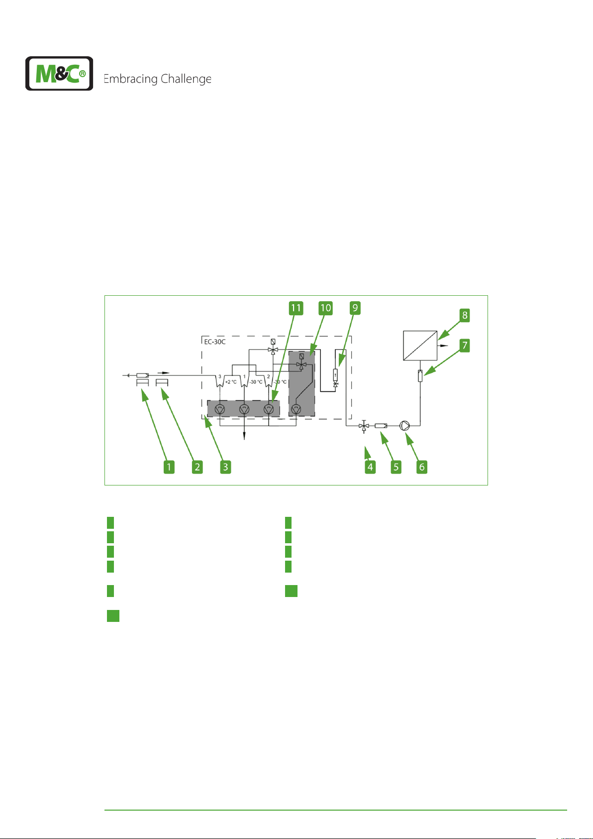
The M&C ultra-low cooler EC-30C is used in the gas analysis technique to reduce the dew
point of humid sample gases and to provide a stable and very low dew point. This eliminates condensate built-up and aerosol formation in the analyzer.
Due to the extremely stable and low gas dew point, there are no water vapor cross-sensitivity and volumetric errors.
Sample gas IN
Condensate OUT
Test gas IN
Fig. 1: Application example of the EC-30C
1 Gas sample probe SP2000-H 2 Electrically heated sample line 4M4/6
3 Ultra-low cooler EC-30C 4 3-way ball valve 3L/PV-1
5 Filter 6 Bellows pump MP-F
7 Aerosol filter CLF -5/W optional depend-
ing on application
8 Analyzer, e.g. PMA1000
9 Flow meter FM40, 25-250 Nl/h 10 Option: 4.peristaltic pump with solenoid valve
(heat exchanger purging)
11 O ption: three SR25.2 peristaltic pumps
(condensate removal)
EC-30C | 1.00.02 +49 2102 935 888 www.mc-techgroup.com 11
Page 13
4.2 Principle
The M&C gas cooler EC-30C is a two stage combination of compressor and Peltier cooler.
The automatic defrost function of the dual deep freezer unit ensures 100 % availability
during operation.
The micro processor-controlled electronics of the EC-30C in combination with the graphical display, offers a high degree of functionality, convenience in use, and safe operation.
The EC-30C is built for 24/7 hours of operating time. The cooling capacity of 130 kJ/h is
constant, even under maximum allowed ambient temperature.
A capacity reserve compensates parts of the natural aging process and maximizes the
service life of the EC-30C.
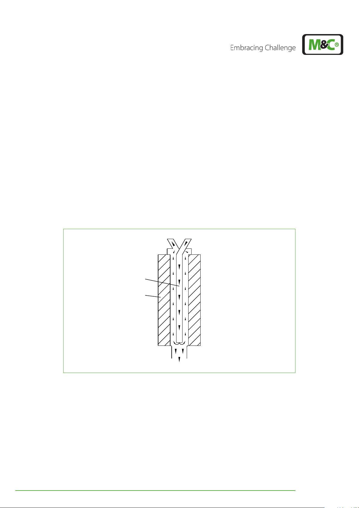
The pre-cooler unit is equipped with a Jet-Stream heat exchanger. The heat exchanger is
cooled down to the constant temperature of +2 °C (35.6 °F) by a separate, microprocessor
controlled, compressor cooling unit.
Sample gas - OUT
M&C Jet-Stream
heat exchanger
Cooling block
Condensate - OUT
Sample gas - IN
Fig. 2: Jet-Stream heat exchanger
The Jet-Stream heat exchanger in the pre-cooler unit removes a large amount of condensate, this ensures a safe and reliable pre-drying of the sample gas. An additional external
vessel to separate the condensate is under normal conditions not necessary. The cooling
unit of the pre-cooler dissipates the heat of the Peltier elements.
The dual deep freezer unit is equipped with two modified Jet-Stream heat exchangers.
Two separate pairs of Peltier elements are cooling the heat exchangers down to a constant
temperature between -20 °C (~-4 °F) and -30 °C (~-22 °F). The factory setting is -30°C (~-22
°F).
12 EC-30C | 1.00.02 +49 2102 935 888 www.mc-techgroup.com
Page 14

The EC-30C switches automatically every 3 hours between the two deep freezer units. The
deep freezer which is currently not in use, will be defrosted to prevent freezing of the heat
exchanger and clogging of the gas lines. Upon special request, this cycle of 3 hours can be
reduced directly at your facility by M&C personnel.
The new graphical user interface is icon-based for easy and intuitive navigation. The messages are displayed in form of easy-to-understand icons. Features like time stamps for the
alarm message history, periodically self-monitoring and pre-warning messages to inform
about upcoming maintenance work ensure a maximum degree of comfort, ease-of-use
and safety of operation of the EC-30C.
The smart periodically self-monitoring of the EC-30C, helps to plan upcoming maintenance and service work to prevent unnecessary down time.
A configurable mA-output is part of the EC-30C standard version.
Three optional peristaltic pumps SR-25.2 for automatic condensate removal can be installed into the unit.
An internal flow meter including an optical flow sensor can be installed into the unit as an
option. Another option would be an external flow meter including an optical flow sensor
or an external humidity sensor.
A fourth optional peristaltic pump can be installed in combination with a second solenoid
valve to provide permanently fresh test gas to the inactive cooling unit. This makes sure
that even in systems, where water vapor cross sensitivity exists, there are no visible peaks
at switching of the dual deep freezer unit. This also prevents short peaks in the sample gas
concentration due to stagnant gas.
EC-30C | 1.00.02 +49 2102 935 888 www.mc-techgroup.com 13
Page 15
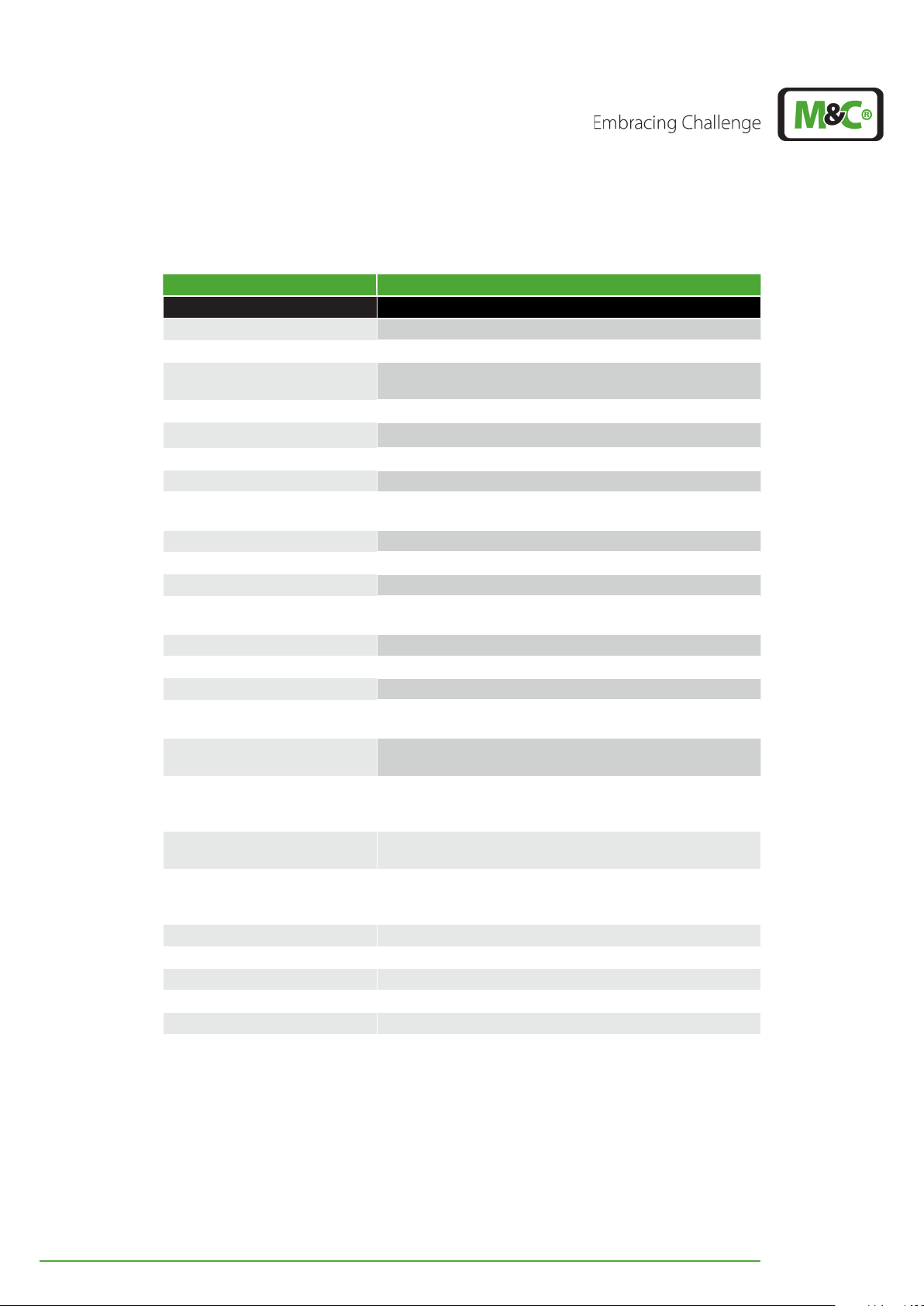
5 Technical Data
Series EC
Part No.: 02 K 6100 (a)*
Gas connection DN 4/6 tube connector
Condensate connections 3x tube connector GL25-12 mm
Material of sample contacting
parts
Single stream, gas flow rate 90 Nl/h – 250 Nl/h
Gas pressure max. 3 bar abs.
Ambient temperature +5 °C to +45 °C (+41 °F to +113 °F)
Storage temperature -20 °C to +60 °C (~-4 °F to +140 °F)
Sample outlet dew point -20 °C to -30 °C (default -30 °C) (~-4 °F to ~-22 °F, default
Sample inlet temperature max. 180 °C (+356 °F)
Water vapor dew point input max. 70 °C (+158 °F)
Cooling capacity max. 130 kJ/h** (at given input conditions)
Main power connection /
Power consumption
Start up time < 60 min
Dead space approx. 160 ml (5.41 fl. oz)
∆P at 250 Nl/h flow rate 5 mbar
Electrical connection 2.5 mm2 (0.0039 in2) terminals, cable glands PG (1 x 12
mA-output 0 - 20 mA / 4 - 20 mA, max. 500 Ohm load (including
Relay output alarm 1 changeover contact: 230 V AC 3 A, 24 V DC 3 A
Relay output warning 1 NO contact, 24 V (AC/DC), 0.5 A
Relay output freezer units I and II1 NO contact, 24 V (AC/DC), 0.5 A
Case protection IP20, EN 60529
Electrical equipment standard EN 61010
Method of mounting 19" rack or wall mount
Case color RAL 9003
Dimension (w x h x d) 84 HP x 8U (with connections) x 360 mm (14.17“)
Weight 39.34 kg (86.73 lbs)
©
Version EC-30C
Duran Glass, PTFE, PVDF
~-22 °F)
230 V, 50 Hz, 380 VA
or* Part-No. …-a=115 V, 60 Hz, 380 VA
mm, 2 x 16 mm, 2 x 20 mm)
cable resistance),
alarm: COM & NC closed
No alarm: COM & NO closed
warning: open
unit I on: closed
unit II on: open
* (a)Addition to the part number for EC-30C with 115 V
** For the given input conditions, please have a look at the table on page 15 chapter ‘5.1 Max.
possible water vapor dew point input [°C] / [°F]’ .
14 EC-30C | 1.00.02 +49 2102 935 888 www.mc-techgroup.com
Page 16
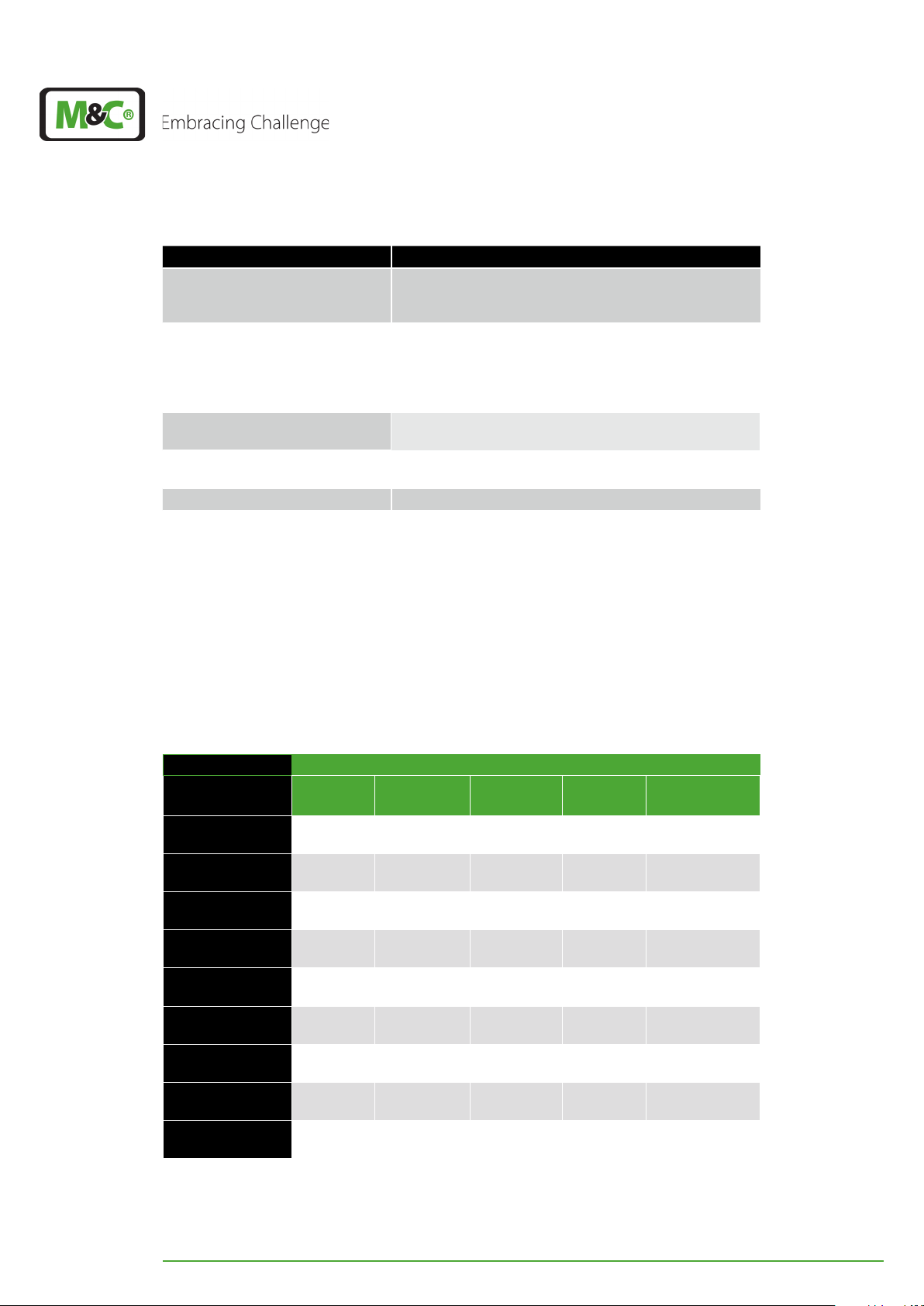
Options
Part-No.: 01 P 9145 Peristaltic pump SR25.2, to mount into the EC-30C (See
spare parts for SR25.2 on page 70 chapter ‘12.3
Spare parts and consumables’ )
Part-No.: 03 F 3000 Aerosol-Filter CLF-5: External mounting in the outlet of
an ultra low gas cooler EC-30C when sample tends to
form aerosols.
Technical data see data sheet 7.7 Fluid particle filter
CLF-5
Part-No.: 02 K 9700 (a)* Heat-exchanger purging: 4. peristaltic pump with
solenoid valve
Part-No.: 03 E 1001 LA 1S humidity sensor, 4 m (13.12 ft) cable with cable
breakage detection
Part-No.: 03 E 3500 FA 20 (Flow sensor with 0.45 m [1.48 ft] cable)
Part-No.: 02 K 9710 FM 40 (Flow meter, 25-250 Nl/h)
* (a)Addition to the part number for EC-30C with 115 V
5.1 Max. possible water vapor dew point input [°C] / [°F]
This table shows the max. possible water vapor dew point input (°C) / (°F) depending on
the incoming gas temperature and the flow rate.
These values correspond to the maximum cooling capacity of 130 kJ/h. The maximum
possible water vapor dew point input (°C) / (°F) indicated must not be exceeded.
Incoming gas temperature in °C (°F)
Gas flow [l/h] 70
(158 °F)
90 70
(158 °F)
110 68
(154.4 ° F )
130 65
(149 °F)
150 62
(143.6 °F)
170 59
(138.2 °F)
190 57
(134.6 °F)
210 55
(131 ° F)
230 53
(127. 4 ° F)
250 52
(125.6 ° F)
90
(194 °F)
70
(158 °F)
67
(152. 6 °F)
64
(147.2 ° F )
61
(141. 8 °F)
58
(136.4 ° F )
56
(132. 8 ° F )
54
(129. 2 ° F )
52
(125.6 ° F)
50
(122 °F)
120
(248 °F)
69
(156.2 °F)
66
(150.8 ° F )
63
(145.4 °F)
59
(138.2 °F)
56
(132. 8 ° F )
54
(129. 2 ° F )
52
(125.6 ° F)
49
(120.2 °F)
47
(116.6 °F)
150
(302 °F)
68
(154.4 ° F )
65
(149 °F)
61
(141. 8 °F)
58
(136.4 ° F )
55
(131 ° F)
52
(125.6 ° F)
49
(120.2 °F)
47
(116.6 °F)
44
(111. 2 ° F)
180
(356 °F)
67
(152. 6 °F)
63
(145.4 °F)
59
(138.2 °F)
56
(132. 8 ° F )
53
(127. 4 ° F)
50
(122 °F)
46
(114 . 8 ° F)
43
(109.4 °F)
41
(105.8 °F)
EC-30C | 1.00.02 +49 2102 935 888 www.mc-techgroup.com 15
Page 17
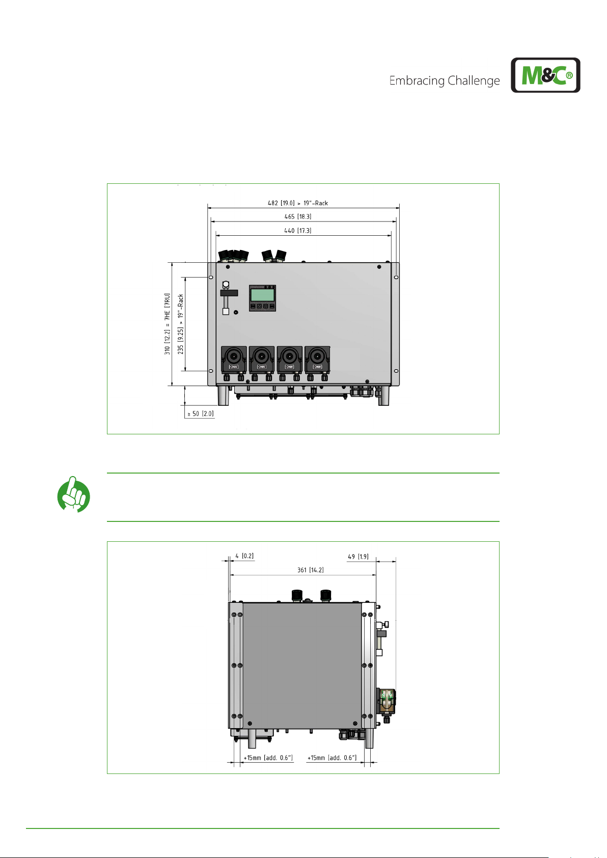
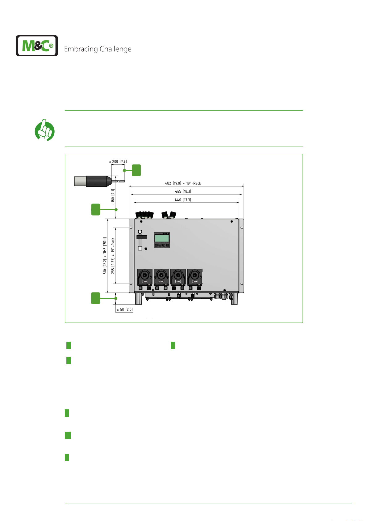
5.2 Dimensions
Dimensions in mm [Inch]
Fig. 3: Front view: dimensions including optional peristaltic pumps
Dimensions in mm [Inch]
Note
You will find mounting directions on page 40 chapter ‘8 Installation instructions and mounting of the EC-30C’ .
Fig. 4: Side view: dimensions including optional peristaltic pumps
16 EC-30C | 1.00.02 +49 2102 935 888 www.mc-techgroup.com
Page 18

6 Receiving the EC-30C
Heavy device!
CAUTION
Note
The ultra-low cooler EC-30C is a complete pre-installed unit.
Please remove the cooler carefully from the packaging. Check the scope of the delivery
specified on the delivery note. Please make sure that you have received all items stated on
the delivery note.
Please check the unit for any transport damages after receipt and report any complaints to
the transport company immediately.
For transport reasons, the heat exchangers are not mounted inside of the cooler. They are
included in the packaging, but wrapped separately. Connect the heat exchangers properly before commissioning.
Risk of injury when handling heavy equipment.
Do not lift, move or carry the device without help. A second person is
required to lift, move or carry the device.
The cooler should always be transported and stored in an upright
position, with the equipment feet facing downwards to ensure that
the oil in the closed compressor circuit cannot run out of the compressor case.
If the device is transported on its back, it needs to be standing in an
upright position for at least 2 hours before turning on.
Follow the instructions to connect the tubing to the heat exchangers
Note
on page 40 chapter ‘8 Installation instructions and mounting of the
EC-3 0 C’
6.1 Product label and serial number
There are two product labels on the EC-30C. One of them is located on the right side of the
cooler and the second one is inside the cooler housing on the bottom plate. Please refer
to this serial number if you have any questions about the device or if you need to order
spare parts or consumables.
Note
The EC-30C features two serial numbers. One serial number is for the
device and the other one for the display controller.
EC-30C | 1.00.02 +49 2102 935 888 www.mc-techgroup.com 17
Page 19
7 Using the EC-30C
PRG
ESC
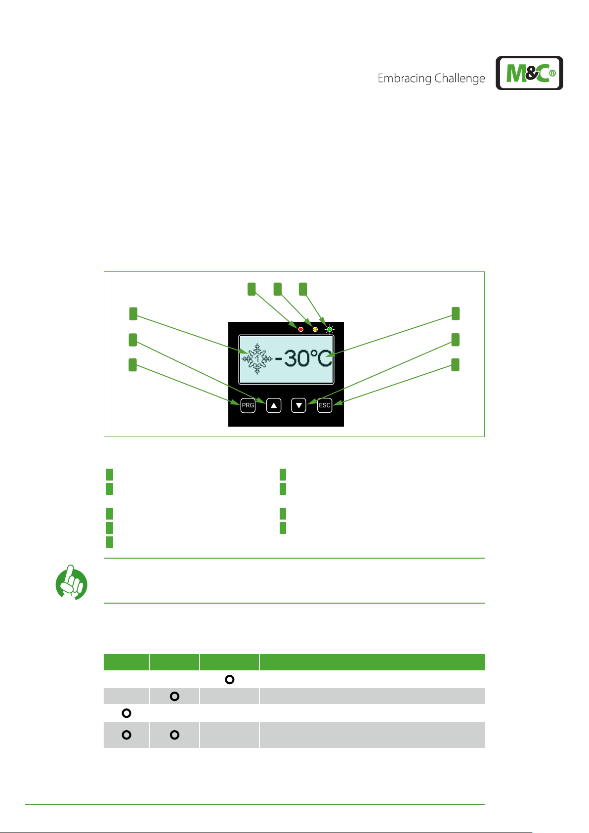
7.1 Graphical user interface (GUI)
The EC-30C has a graphical, icon-based intuitive menu navigation. The graphic user interface includes three LED indicators, the display and the operating buttons. The figure below shows the screen, where the deep cooling unit has reached its target temperature of
-30 °C (~-22 °F), and describes the components of the user interface.
1 2 3
4
5
6
7
8
9
Fig. 5: Graphic user interface
1 Red LED (alarm message) 2 Yellow LED (warning message)
3 Green LED is on (OK) 4 Snow-flake-symbol with ‘1’ in its center (Tempera-
ture ≤ 0 °C and DCU 1 is active)
5 UP button (upwards pointing arrow) 6 PROGRAM button (PRG)
7 Temperature indication 8 DOWN button (downwards pointing arrow)
9 ESCAPE button (ESC)
Note
With the ESC button you will return to the start screen from any other
screen.
7.2 LED color coding and possible color combinations
Red Yellow Green Description
Everything is OK
One or more warning messages
One or more alarm messages
A combination of one or more alarm messages and
warning messages
18 EC-30C | 1.00.02 +49 2102 935 888 www.mc-techgroup.com
Page 20
7.3 Self-monitoring after powering-on the unit
1
2
PRG
ESC
1 2 3
4 5 6
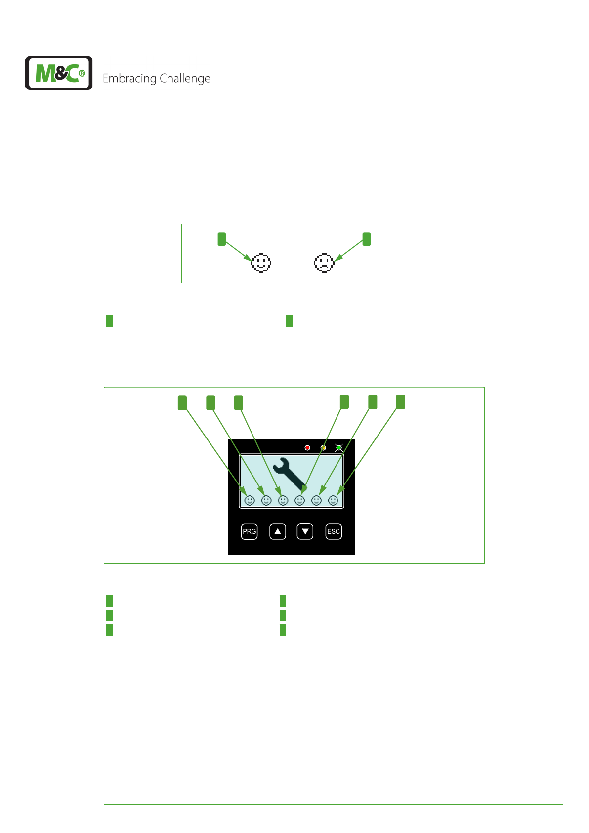
The EC-30C automatically monitors and controls its correct functioning and the wear out
of its components. The self-test includes six different tests, each of them being symbolized
by a smiley icon.
Fig. 6: Smiley symbols during self-test
1 ‘Test passed’-symbol 2 ‘Test failed’-symbol
Please switch on the EC-30C. After powering-on the unit starts the self-testing. After successful self-testing the display shows the following picture.
Fig. 7: The smileys on the display after self-testing
1 Internal low voltages 2 Power supply voltage
3 D/A converter 4 0-20 V-Module
5 Peltier elements 6 decoupling capacitor/ rectifier
If the self-test has succeeded, the unit enters the start-up phase and starts cooling.
If the display shows a ‘Test failed’-symbol, this means that an error has been detected
which prevents the correct operation of the unit.
In case of a failed self-test the display alternates between the monitor with smiley symbols
and the service monitor. These monitors will be shown on the display until the fault is
cleared.
EC-30C | 1.00.02 +49 2102 935 888 www.mc-techgroup.com 19
Page 21
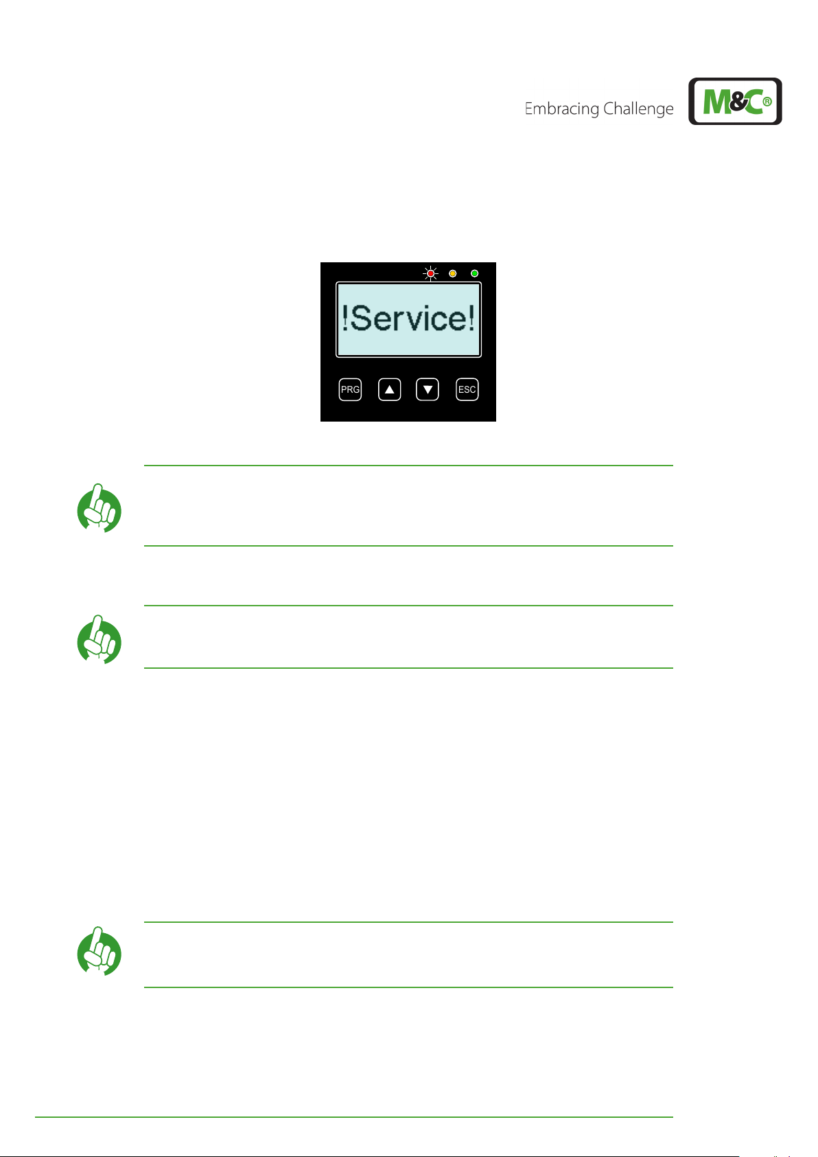
Please contact the M&C Service in case of self-test failures. The M&C Service will recom-
PRG
ESC
mend suitable measures to repair the unit.
Fig. 8: ‘Service‘-monitor: Self-test failed
In some cases it is helpful to switch off the unit and to switch it on
Note
again after approx. one hour.
If a ‘Test failed’-symbol is shown again after that, please contact the
M&C Service!
7.4 Self-monitoring during operation
Note During its regular operation the unit runs automatic self-tests.
7.4.1 Power consumption readjustment
Over time the signs of aging of the Peltier elements increase gradually the value of the
internal resistance. As a consequence the power necessary to keep the target temperature
constant can not be supplied anymore. The projected capacity reserve compensates this
unavoidable aging effect and maximizes the service life of the EC-30C.
7.4.2 Pre-warning messages
If the capacity reserve has been exhausted up to a critical value, the unit will show a warning message about the upcoming failure. An exact definition of the remaining time, until
the breakdown of the unit, is not possible.
Please plan servicing the unit ahead of time. The remaining service
Note
life of the unit after the failure warning can not be determined
exactly.
If the reserve capacity is exhausted, an alarm message will occur. The unit still keeps on
cooling, but the target temperature will not be reached any more. The longer the unit will
be kept in this modus, the less it will be able to cool. The possible cooling temperature will
constantly rise.
20 EC-30C | 1.00.02 +49 2102 935 888 www.mc-techgroup.com
Page 22
If the operation process allows it, it is possible to set the target temperature a little bit
PRG
ESC
2 3
higher, e.g. to -25 °C or -20 °C (~-13°F or ~-4°F). This will delay the alarm message until the
capacity reserve will be exhausted even for this higher target temperature.
7.5 Display during start-up of the EC-30C
The start screen will always show the temperature of the active
deep-cooling unit (DCU).
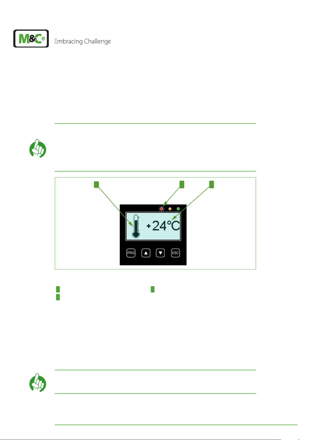
At the beginning of the start-up phase the temperature will decrease
Note
very slowly, given that the active DCU is cooled only via the passive
pre-cooler unit (PCU). After the PCU reaches +2°C (35.6 °F), the active
cooling phase of the DCU starts. From this point on, the temperature
will decrease considerably faster.
1
Fig. 9: Start-up phase: first cooling phase
1 ’Falling’ thermometer 2 Red LED is on (alarm)
3 Temperature of the active DCU
Directly after the successful self-test, the EC-30C will start cooling the pre-cooling unit
(PCU) to +2°C (35.6 °F) (target temperature of the pre-cooling unit). Depending on the
load, the compressor of the pre-cooling unit will switch between 12 to 120 times per hour,
in order to reach this target temperature.
The ‘falling’ thermometer is the symbol for this first cooling phase. At this point the initial
dew point of the sample gas is still higher than 0 °C (32 °F), which means that the target
temperature has not been reached yet, and the EC-30C is still in alarm modus.
Note
The red LED shows the status of the alarm relay. Operation mode of
the relay (safety first): alarm active = red LED
EC-30C | 1.00.02 +49 2102 935 888 www.mc-techgroup.com 21
Page 23
PRG
ESC
1
2 3
PRG
ESC
2 3
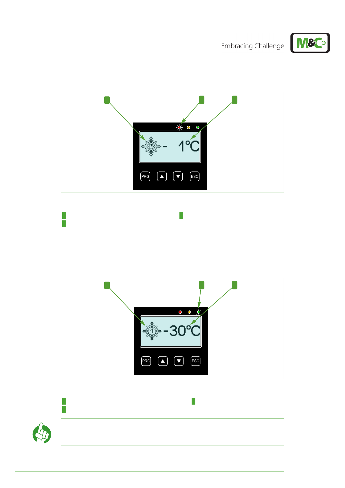
Fig. 10: Start-up phase: TKS reaches and/or exceeds ‘0 °C / 32 °F’-limit
1 Snowflake-symbol with a clock in its center 2 Red LED is on (alarm)
3 Temperature of the active DCU
As soon as the first DCU reaches the 0 °C (32 °F) temperature limit, the thermometer-symbol changes to a snowflake-symbol. The clock in its center stands for the start-up phase of
the active DCU. The EC-30C is still in alarm modus (red LED is on), because the DCU has not
reached its target temperature yet.
1
Fig. 11: Start-up phase: Target temperature reached
1 Snowflake-symbol with ‘1’ for DCU 1 2 Green LED is on (ready for operation)
3 Temperature of the active DCU (here DCU 1)
Note
The ‘1’ in the center of the snowflake stands for the active deep-cooling unit DCU 1.
22 EC-30C | 1.00.02 +49 2102 935 888 www.mc-techgroup.com
Page 24
As soon as the EC-30C reaches the target temperature of DCU 1, including the alarm hys-
PRG
ESC
PRG
ESC
3 7
teresis of 5 °C (41 °F), it changes from alarm modus to OK modus. The red LED goes out and
the green LED turns on.
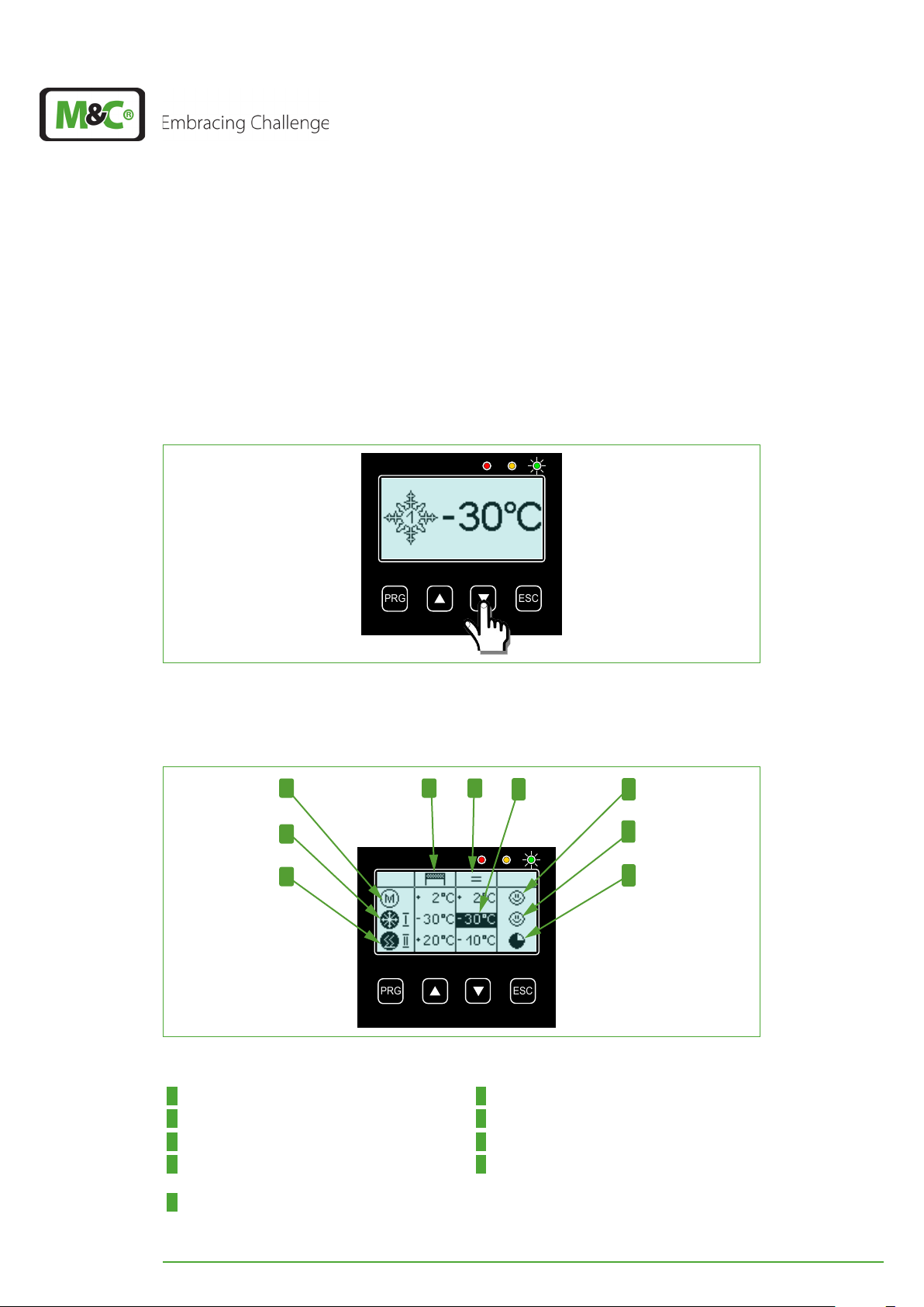
7.6 Overview screen
The overview screen shows detailed information about the pre-cooling unit PCU and the
two deep-cooling units DCU 1 and DCU 2. You can change from the start display to the
overview display by pressing the DOWN button.
Fig. 12: That’s how you reach the overview screen
The icons on the overview screen inform you about the current conditions of the three
cooling units.
4
5
6
Fig. 13: Overview screen
1 2
8
9
1 Column: target-temperatures 2 Column: current temperatures
3 DCU 1 temperature displayed on start screen 4 ‘M‘-symbol: PCU (not active)
5 DCU 1-symbol: cooling (active) 6 DCU 2-symbol: heating (active)
7 Smiley icon: PCU target temperature reached 8 Smiley icon: DCU 1 target temperature
reached
9 Clock icon: DCU 2 target temperature not
reached
EC-30C | 1.00.02 +49 2102 935 888 www.mc-techgroup.com 23
Page 25

The following table shows the icons occurring on the display and their descriptions:
PRG
ESC
Symbol Description
Pre-cooling unit is cooling
Pre-cooling unit is not cooling
Deep-cooling unit I and/or II is cooling
Deep-cooling unit I and/or II is not
cooling
Deep-cooling I or II is heating
Status display:
The unit has reached its target
temperature.
Status display:
A warning or an alarm has occurred
Status display:
The unit has not reached its target
temperature yet
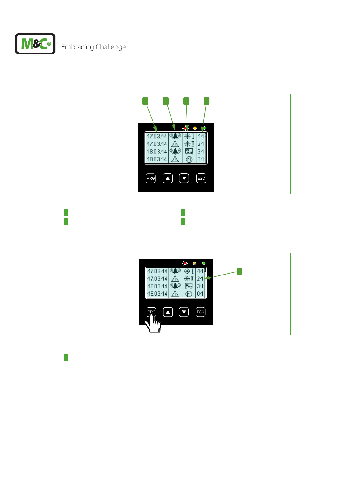
7.7 Alarm and warning history
The alarm and warning history shows in detail all warnings and alarms occurred.
The EC-30C is able to record 768 messages. In case of more than 768 messages the oldest
messages will be deleted and replaced automatically.
You can reach the alarm and warning history from the overview screen by pressing the
DOWN button.
Fig. 14: How to reach the alarm and warning history
24 EC-30C | 1.00.02 +49 2102 935 888 www.mc-techgroup.com
Page 26
PRG
ESC
41 2 3
PRG
ESC
Fig. 15: Alarm and warning history
1 Column: date or time 2 Column: alarm or warning icon
3 Column: component Icons 4 Column: error code
Please press the PRG button to see the messages in detail.
1
Fig. 16: How to chose an alarm or warning message
1 Line, which is highlighted in Fig. 17 and Fig. 18
After pressing the PRG button the last line of the alarm and warning history screen will be
displayed inverted (highlighted).
With the UP and DOWN buttons you can scroll through the stored messages. You will
reach the highlighted message in Fig. 17 by pressing the UP button two-times.
EC-30C | 1.00.02 +49 2102 935 888 www.mc-techgroup.com 25
Page 27
PRG
ESC
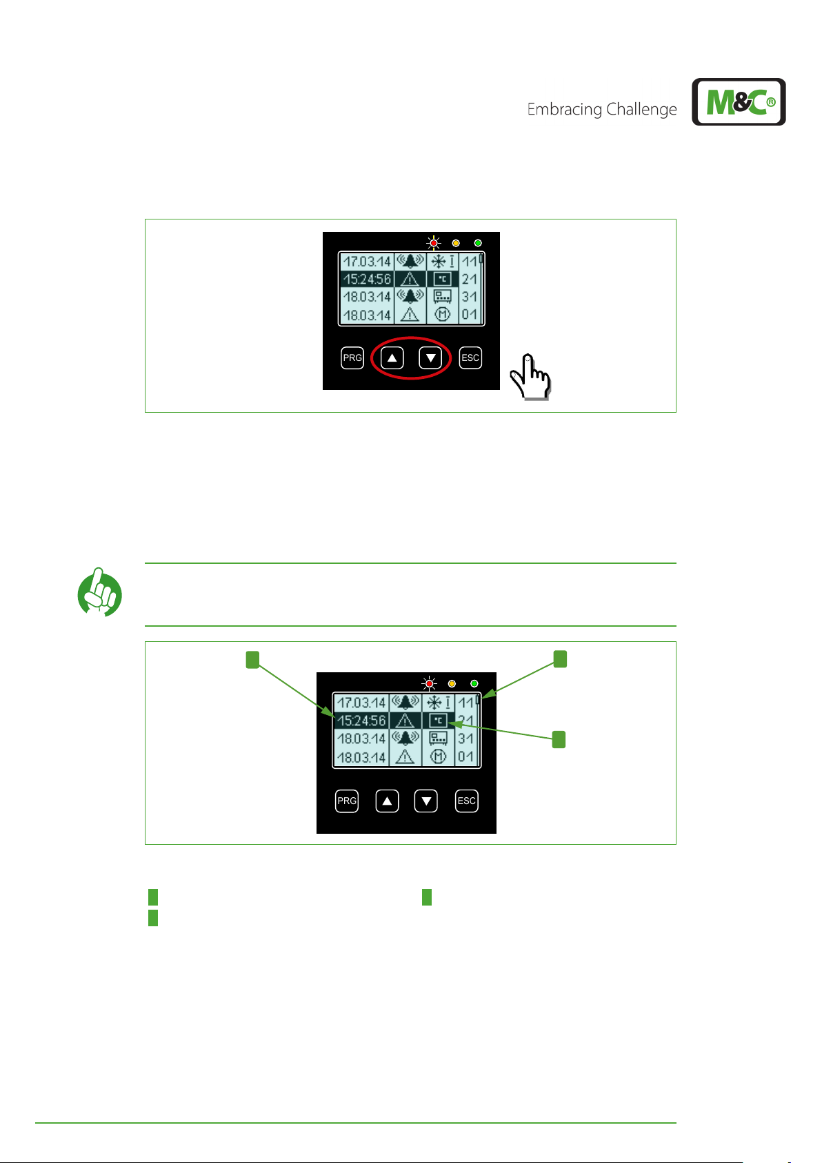
Fig. 17: How to scroll through stored messages
PRG
ESC
2
1
3
The highlighted line will show the time instead of the date of the selected alarm or warning message. The column for component icons will display the component of the device,
the warning or alarm refers to.
In the selected line shown above the DCU 2-icon has changed into the temperature icon,
which means that the warning refers to the temperature of the second deep-cooling unit.
Note
A slider on the right side of the display indicates the current position
in the alarm and warning history.
Fig. 18: Detailed information for a selected message
1 Time of the selected message 2 Slider
3 Temperature icon
26 EC-30C | 1.00.02 +49 2102 935 888 www.mc-techgroup.com
Page 28
7.7.1 Error codes
The error code in an alarm and warning history consists of two digits. The first digit in the
error code refers to the component:
First digit Description
0 Pre-cooling unit
1 Deep-cooling unit I
2 Deep-cooling II
3 General device error
The second digit of the error code offers detailed information about alarm or warning
messages.
The following chapters describe the error codes for warning and alarm messages in
detail.
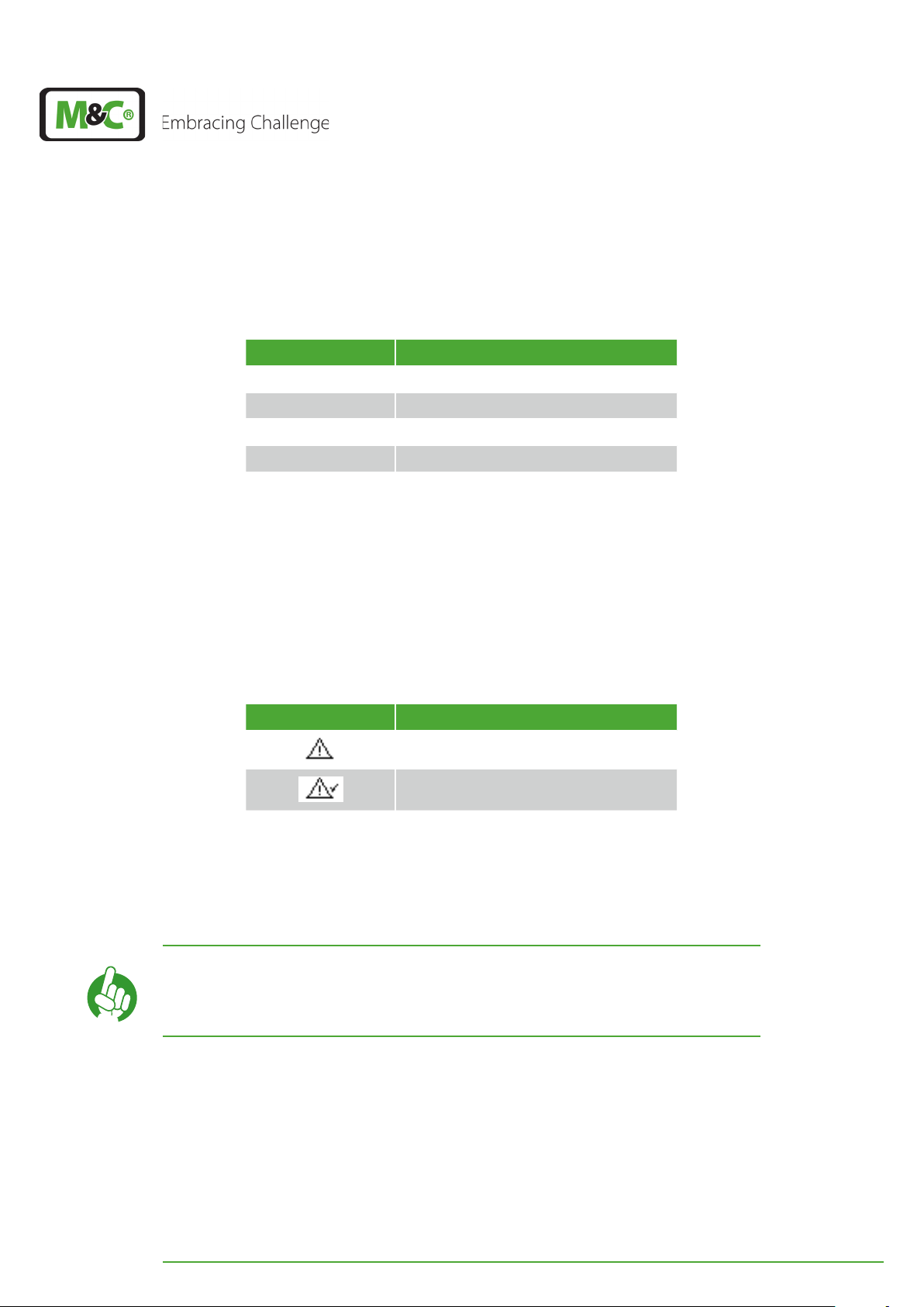
7.7.2 Warning symbols
In the alarm and warning history there are two different warning symbols:
Warning symbol Description
Warning
Canceled warning (warning triangle with
check mark)
The warning triangle stands for a warning. A canceled warning is symbolized by a warning
triangle with check mark.
When a warning has been canceled, the alarm and warning history will show a line displaying a warning triangle with check mark including date and hour of cancellation.
If you want to contact our service department to report a warning or
Note
alarm message, please keep ready the following information:
• Is the message an ‚alarm‘ or a ‚warning‘ message?
• Which error code is being displayed on the screen?
The following table shows the symbols that can occur in case of a warning and explains
their meaning.
EC-30C | 1.00.02 +49 2102 935 888 www.mc-techgroup.com 27
Page 29
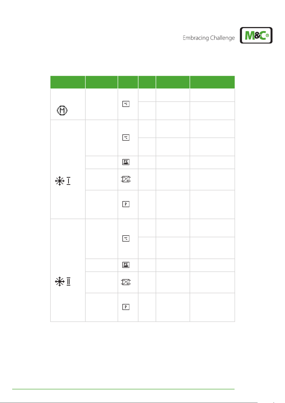
Components
Pre-cooling
unit
Deep-cooling
unit I
Deep-cooling
unit II
Warning
type
Symbol Code Description Comments
01
Temperature
02
10
Temperature
11
Peltierelement(s)
0 - 20 V
Module 1
12 Loss of power U
13
Temperature 14
20
Temperature
21
PeltierElement(s)
0 - 20 V
Module 2
22 Loss of power U
23
Temperature 24
Temperature
too low
PCU takes too
long to cool
down
Cooling
temperature
too low
Heating
temperature
too low
0 - 20 V
Module
deteriorated
Heating/
cooling takes
too long
Cooling
temperature
too low
Heating
temperaturetoo low
0 - 20 V
Module
deteriorated
Heating/
cooling takes
too long
T1 ≤ 0 °C (32 °F)
> 45 min.
T2 < T2
°F)
T2 < T2
°F) after heating
-3 °C (26.6
set
-5 °C (23
set
cycle
≥ 19 V
PE1
U
OUT
≤ U
OUT, set
-0.5 V
or
U
OUT
≥ U
OUT, set
+0.5 V
> 45 min.
Thermal load maybe
too high or ambient
temperature too
high
T3 < T3
°F)
T3 < T3
-3 °C (26.6
set
-5 °C
set
(23 °F) after heating
cycle
≥ 19 V
PE2
U
OUT
≤ U
OUT, set
-0.5 V
or
U
OUT
≥ U
OUT, set
+0.5 V
> 45 min.
Thermal load maybe
too high or ambient
temperature too
high
28 EC-30C | 1.00.02 +49 2102 935 888 www.mc-techgroup.com
Page 30
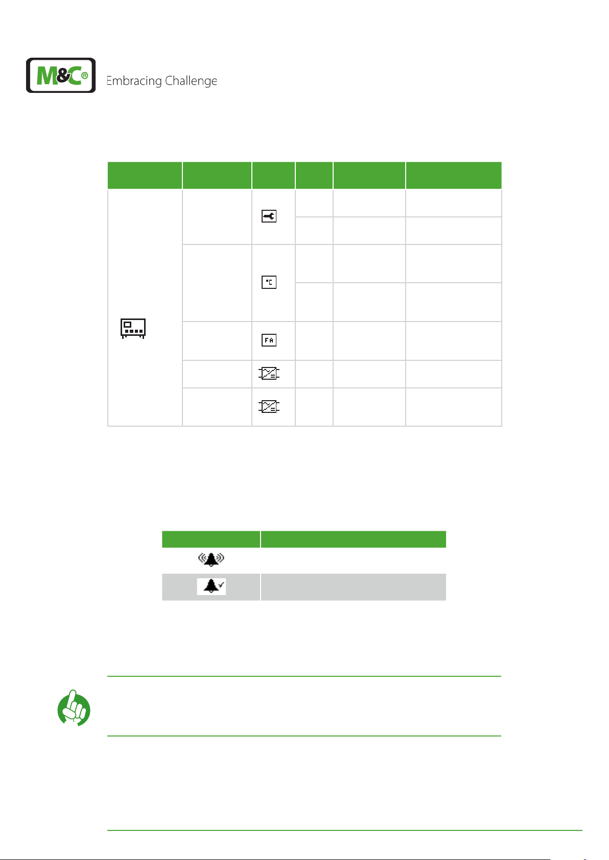
Components
General device
Warning
type
Service
Device
temperature
Gas flow
alarm
Back-up
battery
Decoupling
capacitor or
rectifier
Symbol Code Description Comments
30
31
Service due in
20 days
Service
expired
Service-remaining
time ≤ 20 days
Service-remaining
time ≤ 0 days
Device
32
temperature
too high
T
≥ +70°C (158°F)
device
Device
33
temperature to
low
T
≤ +5 °C (41 °F)
device
Heat exchanger
34 No gas flow
maybe frozen or gas
line defect
35
36
Back-up
battery empty
Power supply
needs to be
checked
≤ 2.3 V
Decoupling capacitor deteriorated or
rectifier defect
7.7.3 Alarm symbols
In the alarm and warning history there are two different alarm symbols:
Alarm symbol Description
Alarm
Canceled alarm (alarm symbol with check
mark)
The bell stands for an alarm. A canceled alarm is symbolized by a bell with check mark.
When an alarm has been canceled, the alarm and warning history will show a line displaying a bell with a check mark including the date and hour of cancellation.
If you want to contact our service department to report a warning or
Note
alarm message, please keep ready the following information:
• Is the message an ‚Alarm‘ or a ‚Warning‘ message?
• Which error code is being displayed on the screen?
The following table shows the symbols that can occur in case of an alarm, and explains
their meaning.
EC-30C | 1.00.02 +49 2102 935 888 www.mc-techgroup.com 29
Page 31
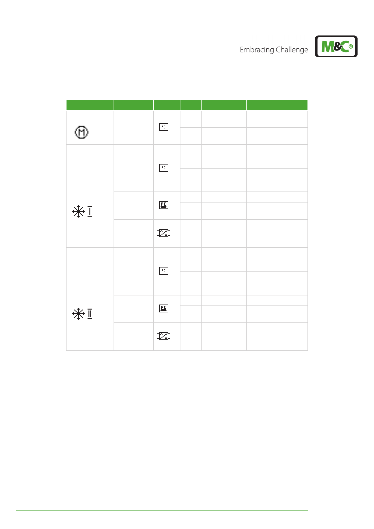
Components Alarm type Symbol Code Description Comments
Pre-cooling unit
Deep-cooling
unit I
Deep-cooling
unit II
Temperature
Temperature
Peltierelement(s)
0 - 20 V
Module 1
Temperature
Peltierelement(s)
0 - 20 V
Module 2
01
02
10
11
12 Loss of power U
13 defect
14 defect
20
21
22 Loss of power U
23 defect
24 defect
Temperature
too high
Temperature
too low
Cooling
temperature
too high
Heating
temperature
too high
Cooling
temperature
too high
Heating
temperature
too high
T1 ≥ +5 °C (41 °F)
T1 ≤ -1 °C (30.2 °F)
T2 ≥ T2
°F)
+3 °C (37.4
set
T2 ≥ +30 °C (86 °F)
≥ 19.7 V
PE1
No cooling despite
the FET, relay etc. OK
U
≤ U
OUT
OUT, set
or
U
≥ U
OUT
OUT, set
T3 ≥ T3
°F)
+3 °C (37.4
set
T3 ≥ +30 °C (86 °F)
≥ 19.7 V
PE2
No cooling despite
the FET, relay etc. OK
U
≤ U
OUT
OUT, set
or
U
≥ U
OUT
OUT, set
-1 V
+1 V
-1 V
+1 V
30 EC-30C | 1.00.02 +49 2102 935 888 www.mc-techgroup.com
Page 32

Components Alarm type Symbol Code Description Comments
30
Liquid
alarm 1
Liquid
Liquid alarm
31
alarm 2
(only for M&C
service
personnel)
Device
32
Device
temperature
33
temperature
too high
Device
temperature
too low
T
≥ +80 °C (176 °F)
Gerät
T
≤ +2 °C (35.6 °F)
Gerät
Couplings
Voltage error 34
capacitor or
bridge rectifier
defect
General device
35
36
I2C communication doesn‘t
work
I2C communication doesn‘t
work
One IC doesn‘t
answer; probably IC
defect
All IC‘s don‘t answer
(probably power
cord defect or
removed)
One internal
Only for
M&C Service
Personnel
37
voltage supply
(5 V or 12 V) is
incorrect
5 V voltage < 4.5 V
12 V Voltage < 9 V
Cools down, but
38
H/K Relay unit
1 defect
does not heat up, or
heats up, but does
not cool down
Cools down, but
39
H/K Relay unit
2 defect
does not heat up, or
heats up, but does
not cool down
EC-30C | 1.00.02 +49 2102 935 888 www.mc-techgroup.com 31
Page 33

7.8 Temperature diagrams
PRG
ESC
PRG
ESC
The EC-30C shows the temperature diagrams of the pre-cooling unit and the two
deep-cooling units. The temperature diagrams display a time period of 6 hours.
You can reach the temperature diagrams from the alarm and warning history screen by
pressing the DOWN button.
Fig. 19: How to reach the graphical temperature diagrams
With the UP and DOWN buttons you can switch between the
Note
graphical temperature diagrams of the pre-cooling unit and the two
deep-cooling units.
7.8 .1 Diagram of the pre-cooler unit (PCU)
You can reach the temperature diagram of the pre-cooler unit (PCU) from the alarm and
warning history screen by pressing the DOWN button.
Fig. 20: Temperature diagram of the pre-cooling unit
After the commissioning of the EC-30C, the temperature diagram starts adding measurement readings from right to left. Every three minutes the characteristic line is updated with
a new temperature value. The diagram always shows the measured temperature of the
last 6 hours. Temperature values older than 6 hours will be deleted.
The y-axis of the PCU temperature diagram shows a temperature range from -35 °C to +25
°C (~-31 °F to +77 °F). Measured values exceeding or going below this temperature range
will not be displayed.
32 EC-30C | 1.00.02 +49 2102 935 888 www.mc-techgroup.com
Page 34

7.8 . 2 Diagram of the deep cooling units (DCU 1 and DCU 2)
PRG
ESC
Starting from the pre-cooling unit (PCU) temperature diagram screen, please press the
DOWN button to reach the temperature diagram of the two deep-cooling units. Here
both deep-cooling units are displayed in one diagram.
The fine line shows the temperature characteristic of DCU 1 and the thicker line shows the
characteristic of DCU 2.
1 2
Fig. 21: Temperature diagram of the deep-cooling units
1 Diagram of DCU 1 2 Diagram of DCU 2
The temperature range of the y-axis is limited from -35 °C to +25 °C (~-31 °F to +77 °F).
Measured values exceeding or going below this temperature range will not be displayed.
Broken temperature lines are caused by switching the unit off and on
again.
Note
When the EC-30C is turned off, and for excample after 2 hours turned
on again, the temperature of the deep-cooling units will have
changed. This leads to a broken line in the diagram.
EC-30C | 1.00.02 +49 2102 935 888 www.mc-techgroup.com 33
Page 35

7.9 Parameter menu
PRG
ESC
PRG
ESC
1
2
3
The parameter menu is used for setting the individual parameters e.g. service interval or
deep-cooling temperature. The parameter menu has two screens. You can switch between these screens by using the UP and DOWN buttons.
You can reach the parameter menu from the temperature diagram of the deep-cooling
units by pressing the DOWN button.
Fig. 22: How to reach the parameter menu (screen 1)
The first parameter screen shows the following information:
Operating time of the EC-30C
Requested service interval
Settings for the mA-output
Fig. 23: Parameter menu, screen 1
1 Line 1: operating time 2 Line 2: Service interval in days
3 Line 3: mA-output
34 EC-30C | 1.00.02 +49 2102 935 888 www.mc-techgroup.com
Page 36

In the second part of the parameter menu, there are the following parameters:
PRG
ESC
1
2
3
Required deep-cooling temperature
Current date
Current time
Fig. 24: Parameter menu, screen 2
1 Line 1: Deep-cooling temperature 2 Line 2: Current date
3 Line 3: Current time
Note
You will find the permitted parameter ranges on page 36 chapter
‘7.9.1 Parameter settings’ .
Here are the definitions of the symbols used in the parameter menu:
Symbol Definition
Information about the time period the
unit has already been running
Setting of the required service interval
Setting of the mA-output and of the
correlated temperature interval
Setting the required deep-cooling
temperature
Information: current date
Information: current time
EC-30C | 1.00.02 +49 2102 935 888 www.mc-techgroup.com 35
Page 37

7.9.1 Parameter settings
PRG
ESC
The parameters displayed on the screens can be adjusted within a defined parameter
range.
You can set the following parameters:
Parameter Parameter range Default value
Service interval
mA-output
(power range)
Off (0 days),
1-1095 Tage
0-20 mA,
4-20 mA
365 days
4-20 mA
Min.: -40 °C to -10 °C
mA-output
(correlated temperature range)
(Min: ~-40 °F to 14 °F)
Max.: +10 °C to +60 °C
-30 °C to +30 °C
(~-22 °F to +86 °F)
(Max: +50 °F to 140 °F)
Required deep-cooling temperature
Date
[Day, Month, Year]
Time
[Hour, Minute, Second]
-20 °C to -30 °C
(~-4 to °F to ~-22 °F)
Day: 01 to 31
Month: 01 to 12
Year: 15 to 99
Hour: 00 to 23
Minute: 00 to 59
Second: 00 to 59
-30 °C (~-22 °F)
01.01.16
12:00:00
To reach the program level for setting the parameters please start from the corresponding
parameter screen and press the PRG button.
Fig. 25: How to reach the parameter settings
36 EC-30C | 1.00.02 +49 2102 935 888 www.mc-techgroup.com
Page 38

The screens of the parameter menu are independent screen pages.
PRG
ESC
You can change only the parameters of the screen that is currently
Note
displayed. If you want to change parameters from a different parameter screen, you have to leave the current setting level first by pressing
the ESC button.
The first parameter of the parameter menu will be highlighted. You can switch between
the parameters of this screen page with the PRG button.
First you have to invert the parameter you want to change. Then you use the UP and
DOWN button to switch between the different parameter ranges.
You can exit this screen without changing any parameter by pressing the ESC button.
To accept the value shown on the display, please press the PRG button for about 3 seconds. The parameter will change from highlighted to not highlighted. This means that the
value has been set to the new parameter. You can also change more than one parameter
on the screen, and accept all of them by pressing the PRG button for 3 seconds.
You can exit this program level by pressing the ESC button.
Note
Please find more details about the program levels on page 67
chapter ‘12.1 Overview of the EC-30C screens’ .
7.10 Device information
Please start from the parameter menu (screen 2) and press the DOWN button to change
to the device information screen.
Fig. 26: How to reach the device information
EC-30C | 1.00.02 +49 2102 935 888 www.mc-techgroup.com 37
Page 39
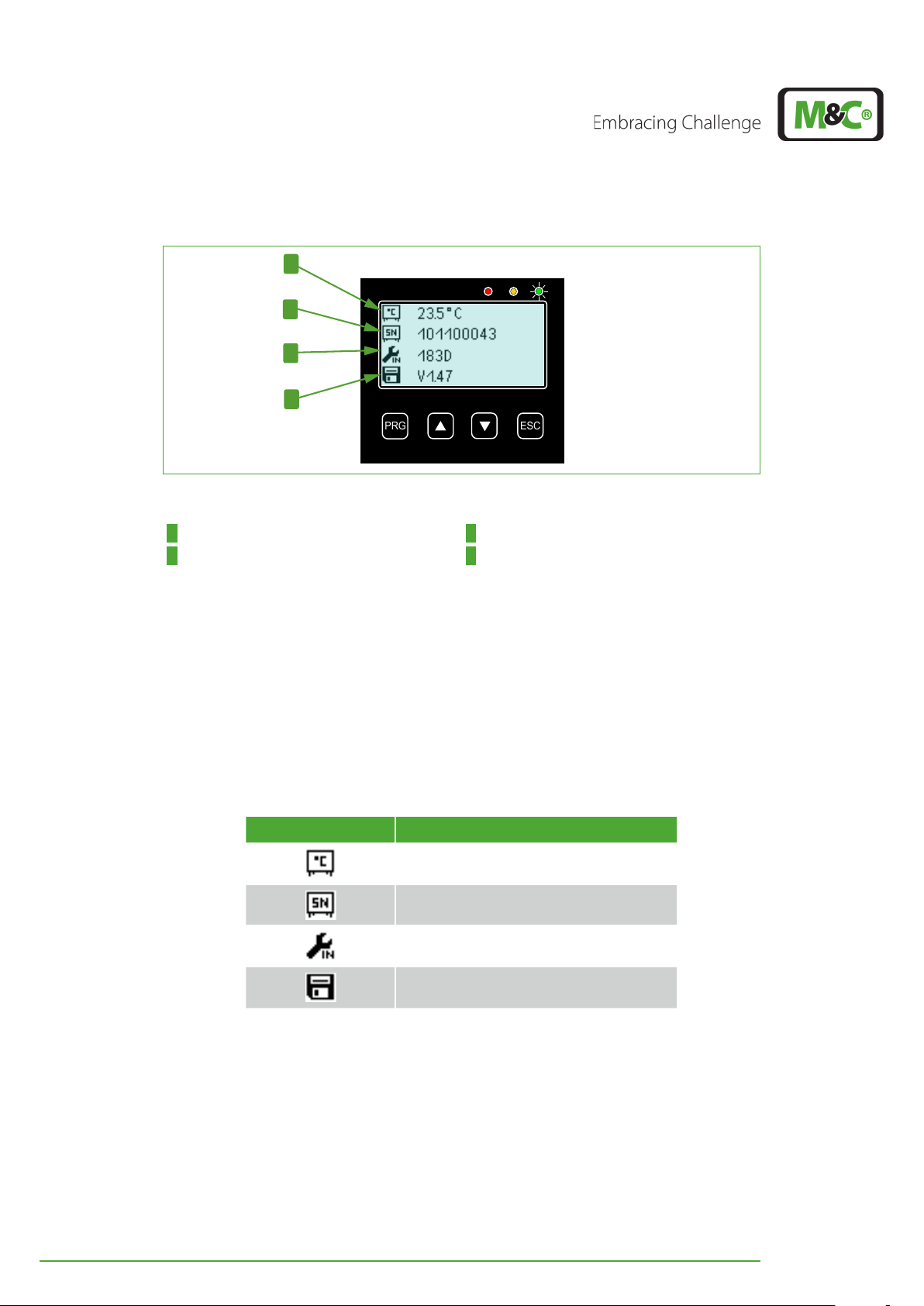
PRG
ESC
1
2
3
4
Fig. 27: Device information
1 Line 1: Device temperature 2 Line 2: Serial number of the display controller
3 Line 3: Days left until servicing 4 Line 4: Software version number
This screen displays the following device information:
Device temperature
Serial number of the device controller
Days left until servicing
Software version number
The symbols used on the device information screen are as follows:
Symbol Description
Device temperature
Serial number of the display controller
Days left until service
Software version number
38 EC-30C | 1.00.02 +49 2102 935 888 www.mc-techgroup.com
Page 40

7.11 Service-Reset (qualified personnel only)
PRG
ESC
Press for 3 seconds
simultaneously
PRG
ESC
Loss of data caused by service reset!
Note
The service reset can be activated from the start screen by pressing simultaneously the UP,
DOWN and ESC button for three seconds.
Fig. 28: Activating Service Reset (Qualified personnel only)
There is no security query, whether you really want to carry out the
service reset or not.
Service reset has to be carried out only by qualified personnel!
After activating service reset all messages from the error memory will be deleted. The
service time will also be reseted.
Fig. 29: Reset screen (Qualified personnel only)
EC-30C | 1.00.02 +49 2102 935 888 www.mc-techgroup.com 39
Page 41

8 Installation instructions and mounting of the EC-30C
Heavy device!
CAUTION
The cooler EC-30C is suitable for both: wall and 19“ rack mounting.
8.1 Installation instructions
Follow these installation instructions:
The operating position of the cooler is exclusively upright. The operation in
vertical position ensures the faultless separation and removal of the condensate in the heat exchanger.
Mount the cooler in a ventilated place away from heat sources. This way you
avoid disturbing heat accumulations.
When mounted outdoors, the cooler has to be installed into a protective case.
Make sure that the place of operation is frost-free in winter and sufficiently
ventilated in summer. Avoid direct sunlight.
Risk of injury when handling heavy equipment.
Do not lift, move or carry the device without help. A second person is
required to lift, move or carry the device.
Take into consideration the required minimum assembly dimensions.
For optimum measurement results we recommend to use an electrically
heated gas sample line.
Heated sample gas lines need to end at least 20 cm (7.874“) before the gas line
reaches the cooler to make sure that the heated sample line and the cooler is
thermally decoupled. That means, the last 20 cm (7.874“) of the gas lines are not
isolated.
Un-heated sample gas lines need to be installed with a declining angle towards
the cooler. In this case, any built-up condensate in the gas lines can flow
towards the cooler and will be removed by the heat exchanger in the pre-cooler unit.
40 EC-30C | 1.00.02 +49 2102 935 888 www.mc-techgroup.com
Page 42
8.2 Wall and rack mount
The tubes for condensate removal will be directly connected to the
Note
DN10/12 mm connectors at the bottom of the heat exchangers.
These condensate removal connectors stick out of the bottom plate
of the cooler housing.
1
2
3
Abmessungen in mm [Inch]
Fig. 30: Min. assembly dimensions (unit with optional peristaltic pumps)
1 Min. distance between isolation and
attachment point of the unit
3 Min. installation space below the
EC-30C
Please follow these instructions for mounting of the EC-30C (numbers correspond to Fig.
30 on page 41):
1 For heated gas sample lines, the insulated part of the line must end at least 200 mm
(7.87“) before the line reaches the device.
2 Please provide a minimum of 180 mm (7.09“) installation space above the unit for the
tubing. Make sure that outgoing air can exit from the upper side of the device.
3 Provide a min. of 50 mm (1.97“) installation space below the unit for tubing, air intake
and maintenance access. Our recommendation: min. 100 mm (3.94“).
2 Min. installation space above the EC-30C
EC-30C | 1.00.02 +49 2102 935 888 www.mc-techgroup.com 41
Page 43
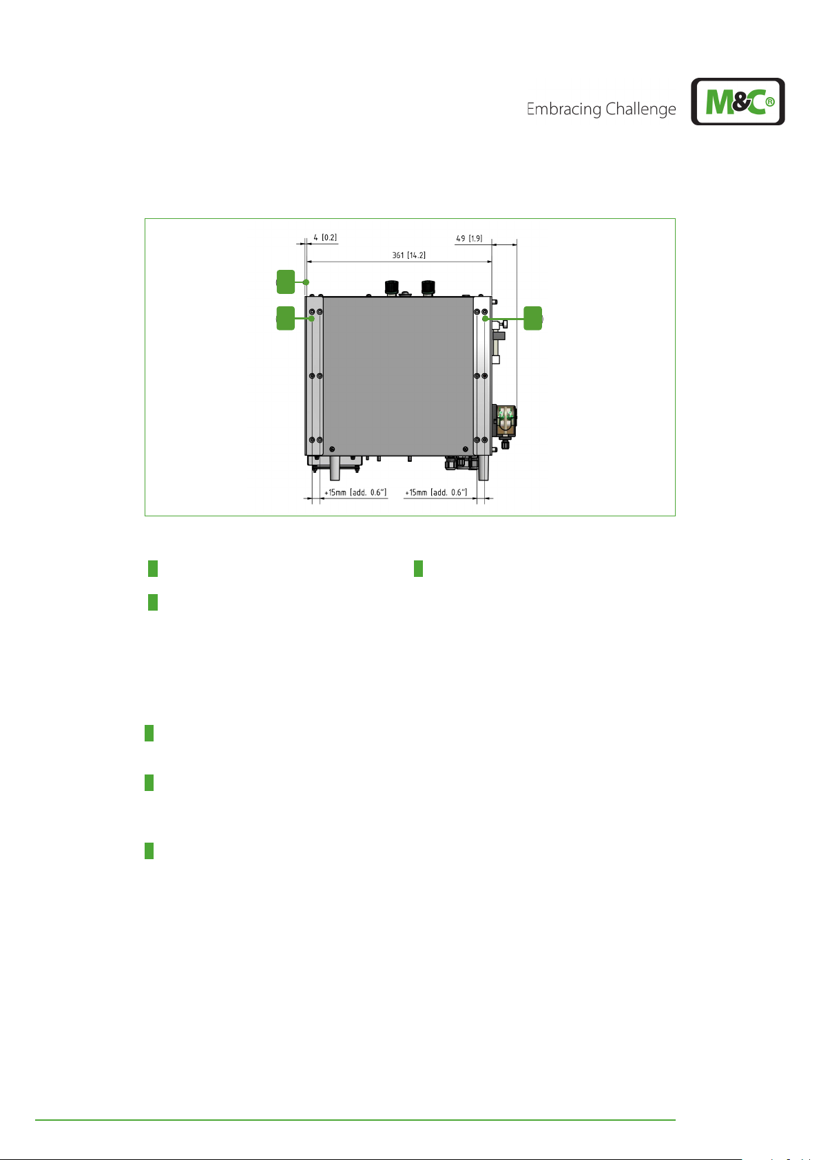
1
2 3
Fig. 31: Mounting rail for wall or rack mounting
Abmessungen in mm [Inch]
1 Back-mounting rail for wall mounting: min.
4 mm (0.16“) wall distance
2 Back-mounting rail for wall mounting: max.
19 mm (0.75”) wall distance
3 Front-mounting rail for 19” rack: housing
front aligned to or 15 mm (0.6“) behind the
front of the mounting bracket
To mount the EC-30C with the provided mounting rails, please follow these instructions
(numbers correspond to Fig. 31 on page 42):
1 The mounting rails can be attached to the side panels close to the rear of the housing.
The minimum distance between the wall and the housing will be in this case 4 mm (0,16“).
2 The mounting rails can be attached to the side panels close to the rear of the housing.
The maximum distance between the wall and the housing will be in this case 19 mm
(0.75“).
3 The mounting rails can be attached to the side panels close to the front of the housing
(19“ rack mount). In this case the front of the housing can either be aligned with or 15 mm
(0.6“) behind the front of the mounting bracket.
42 EC-30C | 1.00.02 +49 2102 935 888 www.mc-techgroup.com
Page 44

8.3 Mounting instructions for SR25.2 peristaltic pump (optional)
Make sure to mount the pump to the front of the cooler with a minimum distance of 3.5
mm (0.138”) and a maximum distance of 5.5 mm (0.216”) between the pump motor and
the front panel.
The minimum distance avoids damages to the pump motor and the maximum distance
prevents the motor shaft from getting loose.
Fig. 32: SR25.2: Mounting distance between pump motor and front panel
1 Pump head (outside the EC-30C housing) 2 Front panel of the EC-30C
3 Recommended mounting distance 4 Pump motor (inside the EC-30C housing)
Note
For more mounting instructions, see the SR25.2 instruction manual.
The manual is available on our website www.mc-techgroup.com.
EC-30C | 1.00.02 +49 2102 935 888 www.mc-techgroup.com 43
Page 45

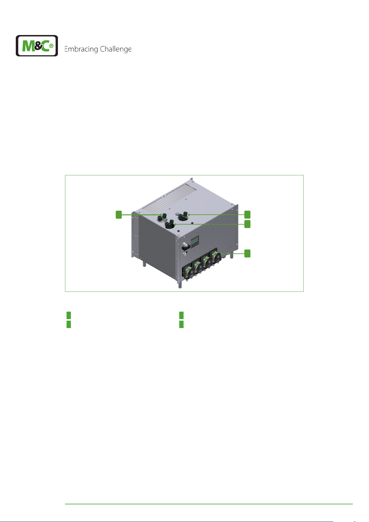
8.4 Tubing without heat exchanger purging (standard tubing)
Do not mix up the tube connectors for sample gas inlet and outlet.
The inlet and outlet connectors of the heat exchanger are marked
with arrows.
Note
Make sure that all the connections are sealed adequately.
To ensure free removal of the condensate, the stated diameters for
the condensate removal lines can not be decreased!
The standard version of the EC-30C is equipped with tubing without heat exchanger purging. This standard tubing includes one solenoid valve (valve 1), to switch between the two
deep-cooling units.
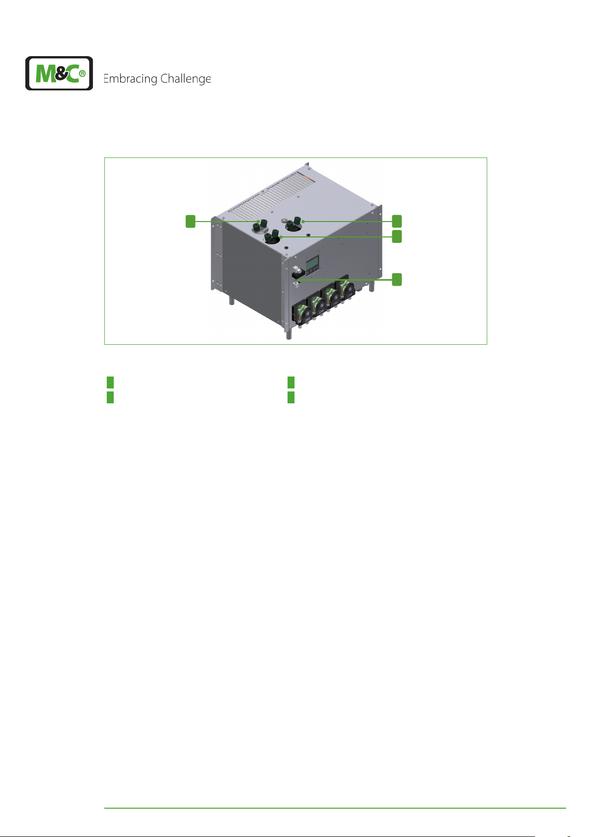
The standard tubing of the EC-30C is shown in the following figure.
2
1
3
4
Fig. 33: Standard tubing: DCU 1 active, solenoid valve triggered, no FA
1 Heat exchanger pre-cooling unit (PCU) 2 Heat exchanger DCU 1 (on the right, here:
active)
3 Heat exchanger DCU 2 (on the left, here:
not active)
Gas IN is the connector of the PCU heat exchanger. The sample gas enters the cooler at
this connection. Gas OUT is the connector at the solenoid valve 1, which sticks out of the
bottom plate of the cooler on the left-hand side. The sample gas leaves the cooler at this
connection.
8.4.1 Heat exchanger connections for tubing without purging
4 Solenoid valve 1
The EC-30C provides six connectors for three heat exchangers, which protrude through
the top panel of the device on the left hand-side. The sample gas enters the cooler at the
sample gas inlet of the PCU heat exchanger.
The sample gas outlet DN 4/6 protrudes through the bottom plate of the cooler close to
the front plate on the left-hand side.
44 EC-30C | 1.00.02 +49 2102 935 888 www.mc-techgroup.com
Page 46
1
2
3
4
Fig. 34: Heat exchanger connectors (device with four optional peristaltic pumps)
1 Heat exchanger pre-cooling unit 2 Heat exchanger DCU 1 (on the right)
3 Heat exchanger DCU 2 (on the left) 4 Flow alarm sensor FA (optional)
The PCU heat exchanger has two connectors which are marked with arrows as gas inlet
and gas outlet. The connectors of the DCU heat exchangers are also marked with arrows.
Connect the gas inlet connectors of the DCU heat exchangers with a tee connector to the
outlet of the pre-cooling heat exchanger.
Route the gas outlets of the DCU heat exchangers through the top panel of the EC-30C to
the inside of the housing. Inside of the device connect the gas outlets of the DCU to the
inlet connectors of the solenoid valve 1. Connect DCU 1OUT to the front and DCU 2OUT
to the back connector of solenoid valve 1.
If you are using an internal flow alarm sensor FA: Connect the outlet of the solenoid valve
1 on the right hand-side to the gas inlet of the flow meter FM 40. Connect the outlet of the
flow meter FM 40 to the gas outlet which protrudes through the bottom plate of the cooler close to the front panel on the left-hand side.
If you are using three optional peristaltic pumps: Connect the heat exchanger outlets to
the peristaltic pumps. Each heat exchanger outlet will be connected to one peristaltic
pump at the front panel of the cooler.
Keep the tubing of the heat exchanger condensate outlets as short and structured as
possible. The tubing does not need to be connected in order.
EC-30C | 1.00.02 +49 2102 935 888 www.mc-techgroup.com 45
Page 47
8.5 Tubing with heat exchanger purging for special requirements
(optional)
Do not mix up the tube connectors for sample gas inlet and outlet.
The inlet and outlet connectors of the heat exchanger are marked
with arrows.
Note
Make sure that all the connections are sealed adequately.
To ensure free removal of the condensate, the stated diameters for
the condensate removal lines can not be decreased!
A fourth optional peristaltic pump can be installed in combination with a second solenoid
valve 2 to provide permanently and slowly (0.3 l/h) fresh sample gas to the inactive cooling
unit. This prevents short peaks of the sample gas concentration due to stagnant gas during
switching between the two deep cooling units.
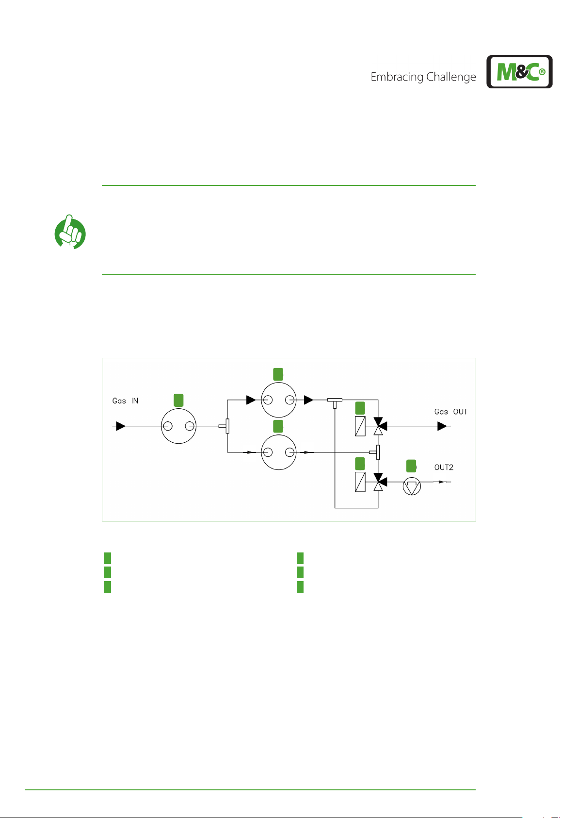
The tubing with heat exchanger purging for special requirements is shown in Fig. 35:
2
90 - 250 l/h
1
3
4
0.3 l/h
5
6
Fig. 35: Tubing with purging: DCU 1 activ, solenoid valves triggered, no FA
1 PCU heat exchanger 2 DCU 1 heat exchanger (right, here: active)
3 Heat exchanger DCU 2 (left) 4 Solenoid valve 1 (right)
5 Solenoid valve 2 (left, optional for heat
exchanger purging)
Gas IN is the connector of the PCU heat exchanger. The sample gas enters the cooler at
this connection. Gas OUT is the connector at the solenoid valve 1, which sticks out of the
bottom plate of the cooler on the left-hand side. OUT2 is the optional connection to the
fourth peristaltic pump, the gas outlet for the heat exchanger purging.
6 Fourth peristaltic pump, optional for heat
exchanger purging
46 EC-30C | 1.00.02 +49 2102 935 888 www.mc-techgroup.com
Page 48
8.5.1 Heat exchanger connections for tubing with purging
The EC-30C provides six connectors for three heat exchangers, which protrude through
the top panel of the device. The sample gas enters the cooler at the sample gas inlet of the
PCU heat exchanger.
The sample gas outlet DN 4/6 protrudes through the bottom plate of the cooler close to
the front plate on the left-hand side.
1
2
3
4
Fig. 36: Heat exchanger connections, tubing with purging
1 Heat exchanger pre-cooling unit 2 Heat exchanger DCU 2 (on the left)
3 Heat exchanger DCU 1 (on the right) 4 Heat exchanger purging: 4. peristaltic pump
(here: on the right)
The PCU heat exchanger has two connectors which are marked with arrows as gas inlet
and gas outlet. The connectors of the DCU heat exchangers are also marked with arrows.
Connect the gas inlet connectors of the DCU heat exchangers with a tee connector to the
outlet of the PCU heat exchanger.
The outlet connector of solenoid valve 2 sticks out of the bottom plate of the cooler located in the middle, close to the front plate. Connect the gas outlet of solenoid valve 2 to the
fourth peristaltic pump.
Route the gas outlet of DCU 1 (on the right) through the top panel of the EC-30C to the
inside of the housing. Inside of the device connect the gas outlet of DCU 1 to the forward-facing connectors of solenoid valve 1 and 2 with a tee.
Route the gas outlet of DCU 2 (on the left) through the top panel of the EC-30C to the inside of the housing. Inside of the device connect the gas outlet of DCU 2 to the backward-facing connectors of solenoid valve 1 and 2 with a tee.
EC-30C | 1.00.02 +49 2102 935 888 www.mc-techgroup.com 47
Page 49

Connect the gas outlet of solenoid valve 1 on the right hand-side to the gas inlet of the
flow meter FM 40. Connect the outlet of the flow meter FM 40 to the gas outlet which
protrudes through the bottom plate of the cooler close to the front panel on the left-hand
side.
Connect the outlet of solenoid valve 2 (left) which protrudes through the bottom plate of
the cooler, in the middle, close to the front plate, to the fourth peristaltic pump.
If you are using three optional peristaltic pumps: Connect the heat exchanger outlets to
the peristaltic pumps. Each heat exchanger outlet will be connected to one peristaltic
pump at the front panel of the cooler.
Keep the tubing of the condensate outlets as short and structured as possible. The tubing
does not need to be connected in order.
8.6 Duran-glass heat exchanger with GL-connections
On mounting the glass heat exchangers, please follow these instructions:
Before mounting the GL connections, please check the PTFE/Silicone locking
rings for damages.
Mount the locking rings with the PTFE side facing the medium.
After assembly please check the leak tightness of the GL connections at the Duran glass
heat exchangers.
8.7 PVDF- heat exchanger with PVDF-tube connectors
Compared to Duran glass heat exchangers, the PVDF heat exchang-
Note
On mounting the PVDF heat exchangers with PVDF compression fittings, please follow
these instructions:
Carefully remove the nut from the screw-connection. Pay attention to the loose
ferrule inside the nut.
Push the union nut onto the 4/6 mm tubing.
Push the ferrule with the thick bulb facing the nut onto the tubing.
Push the tubing onto the support nipple in the screw-connection.
Tighten the union nut hand-tight.
ers have a lower heat conductivity. If you are using PVDF heat
exchangers, please keep in mind, that the cooling capacity of these
heat exchangers are lower.
48 EC-30C | 1.00.02 +49 2102 935 888 www.mc-techgroup.com
Page 50

Note
To tighten the connectors onto the PVDF heat exchanger, hold a
wrench against the spanner flats of the bushing!
After assembling all lines check the leak tightness of the PVDF tube connectors.
8.8 Electrical connections
Wrong supply voltage can destroy your cooler!
ATTENTION
There are two EC-30C versions available: 115 V and 230 V. Make sure to operate each version with the appropriate supply voltage stated on the model type plate.
Note
There are five cable fittings at the bottom of the EC-30C, where all electrical connections
can be lead through.
When connecting the equipment, make sure that the supply voltage
is identical with the information provided on the model type plate!
The installation and commissioning of the device must conform to
the requirements of VDE 0100 (IEC 364) ‘Regulations on the Installation of Power Circuits with Nominal Voltages below 1000 V’ and must
be in compliance with all relevant regulations and standards.
You can open the front of the EC-30C by loosening the four front screws. The front of the
cooler is hooked into the bottom plate with a guide rail and can be tilted to up to 90°
forwards. The power supply electronics are inside the housing on the right. All necessary
connections can be plugged in here without removing the shielding plate.
Fig. 37 shows all available electrical connections.
EC-30C | 1.00.02 +49 2102 935 888 www.mc-techgroup.com 49
Page 51

Transformer out
Fan out
Solenoid valve 1
Solenoid valve 2
Aggregate out
Relay
Relay
Relay
Relay Warning
Relay Warning
Relay
Relay
Fig. 37: Electrical connections
1 X37 2 X38
3 X39 4 X40
5 X41
The pins from Fig. 37 are marked as follows:
Pin No. Definition PIN 1 PIN 2 PIN 3 PIN 4 PIN 5 PIN 6 PIN 7
X37 Power IN PE L N --- --- --- ---
X38 Alarm Relais NO COM NC --- --- --- ---
X39 Warn+Ak.St. W:COM W:NO A.St:COM A.St:NO --- --- ---
X40 mA+LA+FA mA:+ mA:- LA:In LA:GND FA:+5V FA:IN FA:GND
X41 M&C BUS x x x x x x x
x: M&C BUS configuration, only for M&C service personnel.
50 EC-30C | 1.00.02 +49 2102 935 888 www.mc-techgroup.com
Page 52

Note
It is important that the load of the relay contact meets the requirements stated on page 14 chapter ‘5 Technical Data’ .
8.8.1 mA-output
By default, the EC-30C has a configurable mA-output. The mA-output value always corresponds to the temperature of the active deep-cooling unit and represents the current
outlet dew point.
You can assign the mA-output value range (0-20mA or 4-20 mA) to a temperature range
∆T. In this case the lower temperature limit T
mA or 4 mA, and the upper temperature limit T
corresponds to the mA-output signal of 0
min
corresponds to the mA-output signal of
max
20 mA.
This correlation makes it possible to influence the resolution of the mA signal and e.g. to
achieve an improved measuring accuracy for a smaller temperature range.
The measuring error based on the display of the controller is ±2 % of the measuring range
limit.
The maximum load of the mA output including the supply line is 500 Ohm.
You will find information on how to calculate the correlation between
Note
the mA output signal range and the temperature range in the annex
of this manual on page 68 chapter ‘12.2 How to configure the
mA-output’ .
8.8.2 Liquid alarm sensor LA (optional)
It is possible to connect an external liquid alarm sensor LA to monitor the EX30-C, in order
to protect any downstream analyzing equipment. The LA will detect a condensate leakage caused by a possible cooler defect or overload.
The EC-30C connected to the LA gives an alarm signal which will be registered in the alarm
and warning history. The cooler switches the alarm relay to stop the gas supply by either
turning off the sample gas pump or triggering a solenoid shut off valve.
The M&C liquid sensors are based on the principle of electric conduc-
Note
tivity starting from a conductive value of 50 μS/cm.
Learn more about the M&C liquid sensors on our website www.
mc-techgroup.com.
The connecting cable between cooler and external liquid sensor can not exceed a length
of 3 m (19.84 ft.).
EC-30C | 1.00.02 +49 2102 935 888 www.mc-techgroup.com 51
Page 53

The EC-30C can be connected to a liquid sensor with or without cable breakage detection.
The default configuration of the EC-30C is for a sensor with cable breakage detection.
Sensors without cable breakage detection can be connected only to
devices with a specific configuration.
Note
When ordering the EC-30C, please let us know whether you are going
to use a sensor with or without cable breakage detection. We will
configure your EC-30C individually for the required sensor.
Do you need
help?
Do you need further information about liquid sensors? Please
contact the M&C Service!
8.8.3 Gas flow sensor FA 20 and gas flow meter FM 40 (optional)
The M&C gas flow alarm sensor FA 20 is used for monitoring of sample gas or test gas
failures in analyzing devices or analyzing systems. The EC-30C offers the option to process
data coming from the mono-stable gas flow alarm sensor. The gas flow sensor allows both
internal and external mounting.
In case of internal mounting of the FA20, it is necessary to mount into the EC-30C an additional flow meter FM40 with a scale of 0 to 250 l/h.
The flow meter FM40 will be added at the end of the internal tubing. When the flow meter
is triggered, the EC-30C gives a warning message which will be recorded in the alarm and
warning history. This allows to recognize a possible freezing up or leakage in the system at
an early stage.
The connecting cable of an external flow meter must not exceed a length of 3m (19.84 ft.).
Do you need
help?
Do you need further information about gas flow sensors or flow
meters? Please contact the M&C Service!
52 EC-30C | 1.00.02 +49 2102 935 888 www.mc-techgroup.com
Page 54

9 Start-up
Wrong supply voltage can destroy your cooler!
ATTENTION
ATTENTION
When the EC-30C is started, one of the gas lines through the deep-cooler is always open.
The outlet status contact must be connected to an external sample gas pump or a valve
in the sample gas line to protect the entire analysis system by immediately cutting off the
gas supply in the event of error messages of the cooler.
Note
When connecting the equipment, make sure that the supply voltage
is identical with the information provided on the model type plate!
Damages of the downstream analyzers can occur! Observe the alarm
contacts!
Do not extract gas when the EC-30C is turned off or when the LED
light is red!
Disruption in operation possible!
Before starting up the gas cooler make sure that it has been placed in
its operating position for at least two hours! Transport or mounting
can lead to the redistribution of the cooling liquid within the system
and this can cause operating trouble when the cooler is turned on to
early.
Note
The start-up ambient temperature has to be +5 °C to +45 °C (+41 °F
to +113 °F).
9.1 Preparation for start-up
Please take into consideration all equipment and process specific security measures before
initial start-up.
Before initial start-up, follow these steps:
Open the front panel of the EC-30C and connect all cable connections required
(power, relay, mA etc.).
Connect all outputs required and - where necessary - connect them to the
measuring station.
Close and secure the device again.
Apply the correct supply voltage 115 V / 60 Hz o 230 V / 50 Hz according to the
specification plate.
Connect the cooler to the power supply.
The control electronics of the EC-30C permits automatic start up of the cooler, which ensures safe operation regardless of external influences such as a power failure. The error
diagnostic will report possible error sources.
EC-30C | 1.00.02 +49 2102 935 888 www.mc-techgroup.com 53
Page 55

9.2 Temperature chart of the start-up stages
When started up, the EC-30C carries out a self-test to check the main components of the
unit.
The self-test consists of six testing steps. Each of the test steps is symbolized by a smiley
icon. After successful self-testing the unit enters the starting phase and starts cooling.
When the display shows a ‘Test failed’-icon, the unit has detected an error. The cooler will
not enter the start-up phase.
If the self-test has failed, the display alternates between the screen with the smileys and
the service screen. These screens will remain on the display until the problem has been
solved.
Generally in a cases like this the unit has to be sent to M&C for check-up and/or repair.
Please contact our service department by phone before sending the unit.
Note
Please find more details about the self-test on page 19 chapter ‘7.3
Self-monitoring after powering-on the unit’ .
After successful testing, the unit starts the cooling process. It is carried out in several different stages, shown in the following phase diagram.
54 EC-30C | 1.00.02 +49 2102 935 888 www.mc-techgroup.com
Page 56

t [h]
Fig. 38: Temperature chart of the start-up stages
EC-30C | 1.00.02 +49 2102 935 888 www.mc-techgroup.com 55
Page 57

Description of the start-up stages:
1 EC-30C is turned off.
2 EC-30C is turned on. The pre-cooling unit PCU is cooling down to the target
temperature +2 °C (+35.6 °F). Deep-cooling unit DCU 1 (green line) and
deep-cooling unit DCU2 (purple line) are cooled passively by the pre-cooling
unit. The temperatures of DCU 1 and DCU 2 are decreasing.
3 Pre-cooling unit PCU reaches the target temperature of +2 °C (+35.6 °F). The
DCU with the lower temperature (here DCU 1) is cooling down until it reaches
its target temperature of -30 °C (~-22 °F). Second deep-cooling unit (here: DCU
2) is still passively cooled.
4 DCU 1 reaches the target temperature of -30 °C (~-22 °F). DCU 2 heats and
starts defrosting to reach the target temperature of +20 °C (68 °F).
5 DCU 2 reaches target temperature of +20 °C (68 °F). DCU 2 keeps the target
temperature of +20 °C (68 °F) constant for 20 minutes in order to assure a
successful defrost process. DCU 1 keeps a constant target temperature of -30 °C
(~-22 °F).
6 DCU 2 will be turned off. DCU 1 still at target temperature -30 °C (~-22 °F).
Only after a restart of the unit this stage takes a shorter periode of time. This
way the unit can switch very quickly to the dewed DCU and avoid a freeze up.
During operations the length of this stage follows the requirements of the 6
hours‘ cycle time. Because in any case the cooling DCU has to keep the re-
quired target temperature constant for three hours. (see stage 11).
7 DCU 2 cools down to target temperature -30 °C (~-22 °F). DCU 1 keeps
constant the target temperature of -30 °C (~-22 °F).
8 DCU 2 reaches the target temperature of -30 °C (~-22 °F). EC-30C switches the
gas flow to DCU 2. DCU 1 switches off for 20 minutes.
9 DCU 1 heats to the target temperature of +20 °C (68 °F). DCU 2 stays at target
temperature of -30 °C (~-22 °F).
10 DCU 1 reaches target temperature of +20 °C (68 °F). DCU 1 keeps the target
temperature of +20 °C (68 °F) constant for 20 minutes in order to assure a
succesful defrost process. DCU 2 stays at target temperature of -30 °C (~-22 °F).
56 EC-30C | 1.00.02 +49 2102 935 888 www.mc-techgroup.com
Page 58

11 DCU 1 is turned off. DCU 2 stays at target temperature of -30 °C (~-22 °F).
Now the unit „knows“ how long it takes to cool DCU 1 down to the target
temperature of -30 °C (~-22 °F) with the current load. DCU 1 remains off until
the cooling process starts.
It depends on the required cooling process how long DCU 1 remains off. The
goal is to alternate the deep-cooling units every 3 hours, in order to avoid
freeze up of the unit.
12 DCU 1 cools down until the target temperature of -30 °C (~-22 °F) is
reached. DCU 2 stays at target temperature of -30 °C (~-22 °F).
From this moment on DCU 1 starts cooling, to reach the target temperature of
-30 °C (~-22 °F) in due time and to keep the required 6 hours`s cycle time.
13 DCU 1 reaches the target temperature of -30 °C (~-22 °F). EC-30C switches
the gas flow to DCU 1. DCU 2 turns off for 20 minutes.
From this point on the cooling stages of the EC-30C keep on repeating themselves starting
with stage 4. Unlike the restart phase, stage 6 will take a longer time period during the
operation process.
EC-30C | 1.00.02 +49 2102 935 888 www.mc-techgroup.com 57
Page 59
10 Maintenance
Dangerous voltage!
Risk of death by electric shock!
DANGER
Before starting any maintenance work, please make sure that any work done on the device
is in compliance with all relevant regulations and standards.
Depending on the degree of pollution of the ambient air, the cooling fins of the condenser need to be cleaned with pressure air periodically.
The intervals between servicing are dependent on the process and system conditions in
your facility. The facility QA/QC plan should address the frequency for maintenance and
should be updated based on your operations.
10.1 Maintenance of the peristaltic pump type SR25.2 (optional)
DANGER
Do not open the deep-cooler!
Disconnect power supply before opening the device for access.
Make sure that all external power supplies are disconnected.
Dangerous voltage!
Risk of death by electric shock!
Do not open the device!
Disconnect power supply before opening the device for access.
Make sure that all external power supplies, including all alarm and
control circuits, are disconnected.
Flexible tube, conveying belt, contact pulleys and contact springs are the only consumables of the pump. Depending on the operating conditions, the flexible tubing needs to
be checked and, if necessary, changed every three to six months.
The service interval of the EC-30C can be set according to the re-
Note
quired maintenance interval of the peristaltic pump. You can find the
details about setting the service interval on page 36 chapter ‘7.9.1
Parameter settings’ .
Before starting any maintenance work, please make sure that any work done on the device
is in compliance with all relevant regulations and standards.
Note
Please find details to spare parts for the SR25.2 peristaltic pump on
page 70 chapter ‘12.3 Spare parts and consumables’ .
58 EC-30C | 1.00.02 +49 2102 935 888 www.mc-techgroup.com
Page 60

10.1.1 Changing the pump tubing
Aggressive condensate possible!
WARNING
Note
Media residues in tubing!
Chemical burns caused by aggressive media possible!
Wear protective clothing and glasses!
When sending the peristaltic pump to M&C customer service for
repair, please indicate the type of medium pumped. Before shipping
the pump, please remove hazardous or aggressive contaminations
from all parts of the pump!
1
2
3
4
Fig. 39: Changing the pump tubing
1 conveying belt 2 S-bolt
3 tubing 4 contact pulley
For changing the pump tubing please proceed as follows:
Unplug the cooler from the mains voltage. The device needs to be voltage
free.
Open tube connections at the pump; press conveying belt 1 at the recessed
grips and turn S-bolt 2 clockwise up to limit stop;
Remove conveying belt 1 and pull the old tubing 3 at the tube bushings out
of the guides;
Press the two contact pulleys 4 and check whether the spring pressure is still
sufficient, if not, the contact springs have to be changed (see chapter 7.4.1 on
page 20).
Put the new tubing 3 with the tube bushing into the guides of the conveying
belt 1 ;
EC-30C | 1.00.02 +49 2102 935 888 www.mc-techgroup.com 59
Page 61
Use only the original M&C spare parts!
Only the use of the original tubing set guarantees a perfect
operation!
Note
Never lubricate tubing!
Before mounting the pump, check all parts for contaminations and
clean if necessary.
Put the conveying belt 1 with the new tubing 3 into the dovetail guide of the
pump body;
Press conveying belt at the recessed grips and simultaneously turn the S-bolt 2
anticlockwise until it snaps;
Switch on the EC-30C.
10.1.2 Changing the contact pulley and springs
While mounting, make sure that the center of rotation and the driver
Note
are aligned.
Use genuine spare parts only!
Follow these instructions to change the contact pulley and springs:
Disconnect the cooler from the power supply.
Unscrew the nut of the pump head (wrench size 5.5).
Remove the pump head from the motor shaft. Now the driver can be removed
from the pump head and is ready for maintenance.
The removal of the springs (4 pcs.) away from the driver is possible without any
tools. Therefore press together the spring and pull it out of the groove in the
driver, respectively out of the boring of the roll shaft. Now the roll shaft can be
dismounted and the contact pulleys can be replaced.
Assemble the pump in reversed order.
10.1.3 Cleaning the pump head
Aggressive condensate possible!
WARNING
Media residues in tubing!
Chemical burns caused by aggressive media possible!
Wear protective clothing and glasses!
We recommend to clean the parts with a dry cloth. Solvent should not be used, because
it can damage the plastics and synthetic rubber parts. Use oil-free compressed air to clean
the parts if available.
60 EC-30C | 1.00.02 +49 2102 935 888 www.mc-techgroup.com
Page 62
10.2 Changing the heat exchanger
Removal of the heat exchangers may be necessary to carry out any maintenance or repair
work. The PCU heat exchanger can be disassembled without switching off the cooler.
The DCU 1 and DCU 2 heat exchangers need to be defrosted before disassembly. At operation temperatures of -30 °C (~-22 °F) the deep-freezer heat exchangers can not be disassembled because of freezing. Only after a defrost period of about one hour, the DCU heat
exchangers can be removed.
We recommend the following procedure to replace the heat exchangers:
Purge the heat exchanger to remove any possible residue of aggressive media.
Release the upper gas connections and lower condensate connections by
turning the green GL-connectors to the left.
Pull the heat exchanger upwards and slightly rotate it out of the cooling block.
Dry and clean the opening of the aluminum cooling block with a cloth.
Apply a thin and equal layer of thermal conductivity paste over the whole
surface of the heat exchanger to ensure good conduction of heat.
Lightly push and slightly rotate the heat exchanger back into the opening of
the cooling block and press it to the upper block.
Remove any surplus thermal conductivity paste.
Reconnect the tubing following the instruction in chapter 8.4 on page 44 or
chapter 8.5 on page 46.
Note
Do not use force to remove frozen DCU heat exchangers! Glass heat
exchangers might break!
Note Do not mix up DCU and PCU heat exchangers!
Note
Do not mix up tubing!
The outlet tube of the DCU 1 has a red mark.
Special instruction for Duran glass heat exchanger assembly:
Check the PTFE/Silicon locking rings for damage. In assembly, the locking rings
must have the PTFE side facing the medium, otherwise the required degree of
sealing cannot be guaranteed!
Fasten the green GL-connection hand-tight by turning them to the right.
EC-30C | 1.00.02 +49 2102 935 888 www.mc-techgroup.com 61
Page 63

10.3 Changing the 0-20 V-Module
Dangerous voltage!
Risk of death by electric shock!
DANGER
If the self-test during start-up of the EC-30C fails and the fourth icon shown on the screen
is a ‘Test failed’-icon, or if an alarm signal with the codes 14 or 24 is issued during operation,
the 0-20 V-Module has to be changed. If a warning message with the codes 13 or 23 is
shown, changing the module is not yet necessary, but recommended, to avoid breakdown of the unit.
Follow these steps to change the 0-20 V-Module:
Disconnect the cooler from the power supply.
Unscrew and open the front panel, but keep it hinged to the rail at the bottom
plate.
Disconnect the electrical connectors X12, X13, X16, X17 and X18.
Unscrew the electronics cover from the front panel and remove it.
Do not open the device!
Disconnect power supply before opening the device for access.
Make sure that all external power supplies, including all alarm and
control circuits, are disconnected.
Carefully unplug the connector between main board and 0-20 V-Module
electronics.
Open the two screws which are holding the 0-20 V-Module. Replace the
module.
Carefully plug in the connector between main board and the 0-20 V-Module
electronics.
Fasten the electronics cover back to the front panel again.
Connect the plugs X12, X13, X16, X17 and X18 again.
Close and secure the front panel.
Turn on the device and check the result.
62 EC-30C | 1.00.02 +49 2102 935 888 www.mc-techgroup.com
Page 64

10.4 Changing the buffer battery
The EC-30C uses a type CR2032 buffer battery. To change the buffer battery please carry
out the steps indicated below:
Disconnect the EC-30C from the power supply.
Unscrew and open the front panel, but keep it hinged to the rail at the bottom
plate.
Unplug the connectors X12, X13.
Unscrew the electronics cover from the front panel and remove it.
Now you can change the battery.
Fasten the electronics cover back to the front panel.
Plug in the connectors X12, X13.
Close and secure the front panel.
Turn on the unit.
Set date and time.
EC-30C | 1.00.02 +49 2102 935 888 www.mc-techgroup.com 63
Page 65

10.5 Checking the temperature sensors
All temperature sensors of the PCU, DCU 1 and DCU 2 are PT100 sensors.
The diagram below shows the resistance - temperature characteristics of the temperature
sensor PT100.
Fig. 40: Resistor - temperature characteristic of the PT100
If there are any problems during temperature measurements, please follow these steps to
check the PT100:
Disconnect the unit from the power supply.
Unscrew and open the front panel, but keep it hinged to the rail at the bottom
plate.
Unscrew the faulty temperature sensor.
When the EC-30C has been in operating mode before, please wait until the
temperature of the PT100 has adapted to the ambient temperature.
Check the resistance of the PT100 with an ohmmeter.
Compare the measured value with the value of the resistance at ambient temperature
shown in the resistance- temperature diagram. If the measured value corresponds to the
diagram value with good approximation the PT100 is in working conditions. A large deviation means either that the temperature of the sensor is not yet adapted to the ambient
temperature or that it is defective.
64 EC-30C | 1.00.02 +49 2102 935 888 www.mc-techgroup.com
Page 66

10.6 Changing the compressor unit
The compressor unit is connected to the electrical connections shown in Fig. 37 on page
50. The following figure shows the electrical connections of the compressor.
1
3
2
4
5
6
Fig. 41: Compressor: electrical connections
1 Compressor 2 Terminal area inside the compressor terminal box
3 Starting capacitor of the compressor 4 Controller cable from the main electronics
5 Connection wires 6 Flat connector
The four wires of the compressor unit are marked with the numbers ‘1’‚ ‘2’, ‘3’ and the letter
combination PE. These characters are printed on the power supply board belonging to
terminal X35. Connect the wires to the corresponding numbers and letters.
Connect wires in the correct order!
ATTENTION
Make sure to pay attention to the order of the printed numbers and
letters!
EC-30C | 1.00.02 +49 2102 935 888 www.mc-techgroup.com 65
Page 67

11 Decommissioning
Aggressive condensate possible!
WARNING
ATTENTION
When the EC-30C is out of operation, one of the gas lines through the deep-cooler will
always remain open. If a sample gas pump is in-line before or after the EC-30C, downstream analyzing units can be damaged.
Turn off the sample gas pump before decommissioning the EC-30C.
It is recommended to connect the status contact output with an external sample gas
pump or a solenoid valve in the gas line. In case of an alarm message this can protect the
whole analyzing system by immediate interruption of the gas supply.
The alarm relay of the EC-30C can be used to interrupt the gas supply either by turning off
the sample gas pump or by triggering the shut-off solenoid valve.
Media residues in tubing!
Chemical burns caused by aggressive media possible!
Wear protective clothing and glasses!
Damages of the downstream analyzing units possible!
Turn off up- or downstream sample gas pumps before
decommissioning!
Note
Please find further details about the alarm relay on page 51 chapter
‘8.8.2 Liquid alarm sensor LA (optional)’ .
In case of a short-term decommissioning of the cooler no special measures are required.
In case of a long-term decommissioning of the coolers we recommend to purge the cooler with inert gas or air.
Remove residual condensate entirely from the cooler.
66 EC-30C | 1.00.02 +49 2102 935 888 www.mc-techgroup.com
Page 68

12 Appendix
12.1 Overview of the EC-30C screens
Level 1
(Main menus)
Level 2
(Parameter)
Level 3
(Values)
Using the UP and DOWN button
to scroll through the alarm
and warning messages
Fig. 42: Overview: screens
EC-30C | 1.00.02 +49 2102 935 888 www.mc-techgroup.com 67
Choose: ‚service interval‘ or
‚mA-output‘
(the choice will be
highlighted)
Choose:
‘, ‚Date‘ and ‚Time‘
‚T
SET
(the choice will be
highlighted)
Set service interval
Set mA-output (0-20 mA
or 4-20 mA)
Assign a temperature
range to the mA-output
Set T
SET
Set date
Set time
Page 69

12.2 How to configure the mA-output
T
(
I
mess
− I
offset
)
∗ ∆T
∆I
+ ∆T
min
0
0
0
m , wenn
− 20
− 20m
m
20 − 20
16
4
4
4
− 20
The mA-output value always corresponds to the temperature of the active deep-cooling
unit. That means, that it always represents the current ouptut dew point. T
temperature limit set in the parameter menu. T
is either assigned to 0 mA or 4 mA. T
min
is the upper temperature limit and is assigned to 20 mA.
By changing the temperature limits, the user can adapt the mA signal to the required temperature range ∆T. This way the resolution of the signal can be influenced.
is the lower
min
max
Depending on the temperature limits set by the user, either ∆T
min
or ∆T
needs to be de-
max
terment first.
12.2.1 How to calculate temperature based on measured mA-value
The temperature of the deep-cooling unit can be determent by using the measured
mA-output values. To calculate the temperature, please use the following formulas:
For T
≤ 0 °C (32 °F):
min
display
For T
min
With the following values for I
> 0 °C (32 °F):
offset
=
= (
and ∆I:
display
offset
∆I =
m
m
m
when
, wenn
when
, wenn
when
, wenn
when
)
m
m
68 EC-30C | 1.00.02 +49 2102 935 888 www.mc-techgroup.com
Page 70

12.2.2 How to calculate mA-value based on measured temperature
I
mess
=
T
+∆T
m
∗ ∆I
∆T
+ I
offset
I
mess
=
T
-∆T
m
∗ ∆I
∆T
+ I
offset
0
0
0
m , wenn
− 20
− 20m
m
20 − 20
16
4
4
4
− 20
when
Based on the displayed deep-cooling temperature, the value of the mA-output can be
determent. For this calculation you can use the following formulas:
For T
For T
With the following values for I
≤ 0 °C (32 °F):
min
(
display
(
> 0 °C (32 °F):
min
(
display
(
and ∆I:
offset
offset
∆I =
Increments and resolution of the mA-output
=
m
m
m
, wenn
when
, wenn
when
, wenn
when
)
)
)
m
m
The mA-output with the 0-20 mA setting has 400 increments per range. For the range of
4-20 mA the increments are proportionally reduced to 320.
Depending on the temperature range (see how to set the temperature range on page
34 chapter ‘7.9 Parameter menu’ ), the resolution or accuracy of the mA-output can be
calculated as follows:
(T
- T
max
) / 400 for 0-20 mA
min
or:
(T
- T
max
) / 320 for 4-20 mA
min
Example:
Set: 4-20 mA for -30 °C to +30 °C (~-22 °F to 86 °F)
The resolution of the mA-output is:
[30 °C - (-30 °C)] / 320 = 0.1875 °C (0.34 °F)
EC-30C | 1.00.02 +49 2102 935 888 www.mc-techgroup.com 69
Page 71

12.3 Spare parts and consumables
The replacement interval for spare parts and consumables depends on the specific operating condition of the analyzer. The quantities recommended in the following table are
based on experience. Your replacement intervals will be based on your operating
conditions.
The product label with the serial number is located on the back of the EC-30C.
Type and name of the product
(C) Consumables
(R) recommended spare parts
(S) spare parts
Part-No. Name C/R/S 1 2 3
90 K 6215 0-20 V Module R - - -
90 K 6210 Main electronics (Var 1) R - - -
90 K 6200 Power supply electronics (Var 1) R - - -
90 K 6205 Rectifier electronics (Var 1) R - - -
90 K 6220 Main adapter R - - -
EE 02710005 Rectifier capacitor R - - -
90 K 6265 Converter R - - -
90 K 6225 Fuse set* EC-30C 230 V R - - -
90 K 6225a Fuse set* EC-30C 115 V R - - -
90 K 1002 Temperature sensor pre-cooling unit PCU R - - -
90 K 0040x Temperature sensor deep-cooling unit DCU R - - -
93 K 0047 Peltier element R - - -
90 K 6245 O-ring set** Silicone EC-30C R - - -
90 K 1014 Cooling aggregate 230 V R - - -
90 K 1014a Cooling aggregate 115 V R - - -
90 K 1055 Starting capacitor: compressor 230 V: 80 µF R - 1 1
90 K 1060 Starting capacitor: compressor 115 V: 160 µF R - 1 1
90 K 6001 Heat exchanger glass DCU R 1 1 1
02 K 9105 Heat exchanger glass PCU R 1 1 1
90 K 6003 Heat exchanger PVDF DCU R 1 1 1
02 K 9300 Heat exchanger PVDF PCU R 1 1 1
90 K 0115 Heat conductivity paste (50 g)***
90 K 6040 Solenoid valve 230 V R - - -
90 K 6041 Solenoid valve 115 V R - - -
90 K 0042 Fan 230 V R - - -
90 K 0042a Fan 115 V R - - -
EZ 0024 Display controller TCU R - - -
91 B 8600 Key-pad R - - -
recommended amount
based on number of
years of operation [years]
70 EC-30C | 1.00.02 +49 2102 935 888 www.mc-techgroup.com
Page 72

Type and name of the product
(C) Consumables
(R) recommended spare parts
(S) spare parts
recommended amount
based on number of
years of operation [years]
Part-No. Name C/R/S 1 2 3
90 P 1007 SR25.2: Tubing set
C 1 2 4
with PVDF-tube connectors 4/6mm, standard
90 P 1020 SR25.2: Driver, complete S - 1 1
90 P 1050 SR25.2: Conveying belt S - 1 2
90 P 1045 SR25.2: Contact pulley SR25 PVDF for driver S 2 4 4
90 P 1010 SR25.2: 1 set (4 pcs) contact springs SR25 for
R 1 2 2
driver
* Fuse set EC-30C includes fuses for main, power supply and rectifier electronics.
** The O-ring set Silicone EC-30C for the deep-cooling units DCU 1 and DCU 2 includes 2 x Ø 60 mm and 3 x Ø 16 mm
O-rings. If you disassemble a deep-cooling unit, you always have to replace all five O-rings.
*** Each heat exchanger delivery includes 5 g (0.011 lb) heat conductivity paste. You will need additional heat conducting paste, if you insert the heat exchanger after cleaning.
12.4 Additional Information
More information about the EC-30C can be found on our website:
www.mc-techgroup.com
12.5 Declaration of conformity
CE - Certification
The EC-30C complies with the following EU directives:
EMC directives
The EC-30C complies with the EC directive 2014/30/EU ‘Electromagnetic compatibility’.
Low Voltage Directive
The EC-30C meets the requirements of the Low Voltage Directive 2014/35/EU.
To ensure the compliance with this EC directive, the EC-30C conforms to the DIN EN 61010
standard.
Declaration of conformity
The EU Declaration of conformity can be downloaded from the M&C website or directly
requested from M&C.
EC-30C | 1.00.02 +49 2102 935 888 www.mc-techgroup.com 71
Page 73

12.6 Certificates
Certificates are available on our website:
www.mc-techgroup.com
12.7 Warranty
In case of a device failure, please contact M&C immediately or your authorized M&C
distributor.
We have a warranty period of 12 months from the delivery date. The warranty covers only
appropriately used products and does not cover the consumable parts. Please find the
complete warranty conditions in our terms and conditions.
The warranty includes a free-of-charge repair at a M&C facility or the free replacement of
the device. If you return a device to M&C, please be sure that it is properly packaged and
shipped with protective packaging. The repaired or replaced device will be shipped free
of delivery charges to the point of use.
For more information about shipping and handling of returned devices, please see on
page 73 chapter ‘12.10 Shipping and handling’ .
12.8 Liability and disclaimer
This instruction manual is an original M&C document. It does not claim to be complete
and it may be subject to technical modifications. We are not responsible for any printing
errors or errors in the content of the manual. Please be assured that precautions have been
taken to prevent errors in our product documentation to provide you with the best possible and accurate information.
Liabilities for indirect and direct damages that are related to the delivery or the usage of
this instruction manual are excluded.
We are not liable for the content of translations from sources which are not authorized by
M&C.
Copy of this document or of its content is not allowed without explicit approval of M&C.
With the release of this version all older instruction manual versions will no longer be
valid.
M&C© is a registered trademark of M&C TechGroup Germany GmbH.
72 EC-30C | 1.00.02 +49 2102 935 888 www.mc-techgroup.com
Page 74

12.9 Storage
If you plan to store your M&C product before installing and operating, please follow these
storage recommendations. Make sure that the device is stored in a protected, dry and well
ventilated area. Please cover the device with an appropriate cover to protect it from dirt
and liquids.
If you have any questions about proper storage of your M&C products, please feel free to
contact us.
12.10 Shipping and handling
If you need to ship your M&C product to another department inside your company or
back to M&C, please follow these shipping and handling recommendations.
Please ship the device in its original packaging. This is the best way to protect the device.
If the original packaging is not available any more, please use a sturdy cardboard box with
enough packaging material to protect the device from damages during shipping.
If you send your M&C product in for maintenance work at our M&C facility, please send the
properly packaged device to the M&C TechGroup address in the USA or Germany as
needed.
12 .11 Proper disposal of the device
At the end of the life cycle of our products, it is important to take care of the appropriate
disposal of obsolete electrical and non-electrical devices. To help protect our environment, please follow the rules and regulations of your country regarding recycling and
waste management.
EC-30C | 1.00.02 +49 2102 935 888 www.mc-techgroup.com 73
Page 75

13 About us
13.1 M&C‘s group of companies
The M&C group of companies with its German headquarter and world wide market activities, has earned the reputation as one of the well-known and strongest partners in the
market.
Our company, our products, special systems and overall performances are well established
in the market. We continuously belong to the best of the best of our industry. This makes
us very proud. Our core competences are to find qualified solutions for even the most
complex and demanding measuring tasks. We are developing answers to solve the technical demands of the future. With our focus on premium services, we are reliable, innovative and an overall cost effective market partner worldwide.
To learn more about M&C, please visit our website:
www.mc-techgroup.com
For even quicker access, please use our QR-code:
74 EC-30C | 1.00.02 +49 2102 935 888 www.mc-techgroup.com
Page 76

13.2 The quality-oriented M&C catalog
M&C offers national and international services, project planning and construction of special systems with a wide range of products. Our catalog covers a large variety of high
quality products with in-depth knowledge of various customer applications. Our product
excellence and innovative solutions continues to make M&C a world class company.
You can find the following product groups in our catalog. The combination of products
from these groups offers a complete solution for most industrial needs. We develop, manufacture and test our products in accordance with a wide range of national and international standards.
Probes Cooler Filter
Comprehensive range of probes with
a large spectrum of available options
for an almost unlimited range of
applications.
Different materials available
(Hastelloy, Titan, PTFE etc.)
Optimised gas and condensate separation, low maintenance and self
monitoring.
Compact design for wall mounting
or 19” rack.
Suitable for all processes, due to the
modular and user-specific configuration
possibilities of the filter components.
Filter enclosures available in glass,
stainless steel, PVDF, PTFE or in different
metal combinations.
Portable components Compact systems Oxygen analyzer
Developed for high quality gas analysis at different locations.
Compact standard systems designed
for a 19” enclosure or a plate structure.
A broad variety of products with high
measuring accuracy.
Direct measuring is based on paramagnetic measuring principle (dumbbell-type).
EC-30C | 1.00.02 +49 2102 935 888 www.mc-techgroup.com 75
Page 77

13.3 Technical consulting services
M&C has earned a reputation as one of the most capable and experienced companies in
the world, especially when it comes to difficult or complex measurement projects. We are
proud that our customers have confidence in our products and continue to experience
repeat business.
We also offer technical consulting for our components, devices and complete systems. We
support our customers in finding individual solutions for their specific measuring tasks.
These individual solutions lead to new concepts of designing and building custom-made
devices or complete systems. The dedication and commitment to finding solutions to the
most complex and challenging tasks for our customers sets us apart from our
competitors.
We have custom-made application experiences in many different fields worldwide. With
this experience we are able to support our customers by seeking and finding errors, trouble shooting during day-to-day operation or identifying hard to find interferences.
13.3.1 Ideas, suggestions and feedback
All our activities are designed to meet and exceed the demands of the market and the
specific interests of our customers. That‘s why M&C is very interested in developing products, processes and services which are in demand and up to date.
This means that your feedback, ideas and suggestions are very important to us.
Please let us know what kind of new improvements and innovations you would like to see
at M&C. Tell us, what you like about M&C and what needs improvement.
Please send us an email or feel free to just call us ...
We appreciate your comment.
76 EC-30C | 1.00.02 +49 2102 935 888 www.mc-techgroup.com
Page 78

Your contact to M&C in Germany and the USA
M&C TechGroup Germany GmbH
Rehhecke 79, 40885 Ratingen
Service phone:
Service e-mail:
M&C TechGroup North America
6019 Olivas Park Drive, Suite G
+49 2102 935 - 888
service-DE@mc-techgroup.com
Ventura CA 93003
Phone:
E-mail:
+1 805 654 6970
info-usa@mc-techgroup.com
Your M&C contacts world-wide
http://www.mc-techgroup.com/en/Locations-and-regions/
EC-30C | 1.00.02 +49 2102 935 888 www.mc-techgroup.com 77
 Loading...