

Page 1
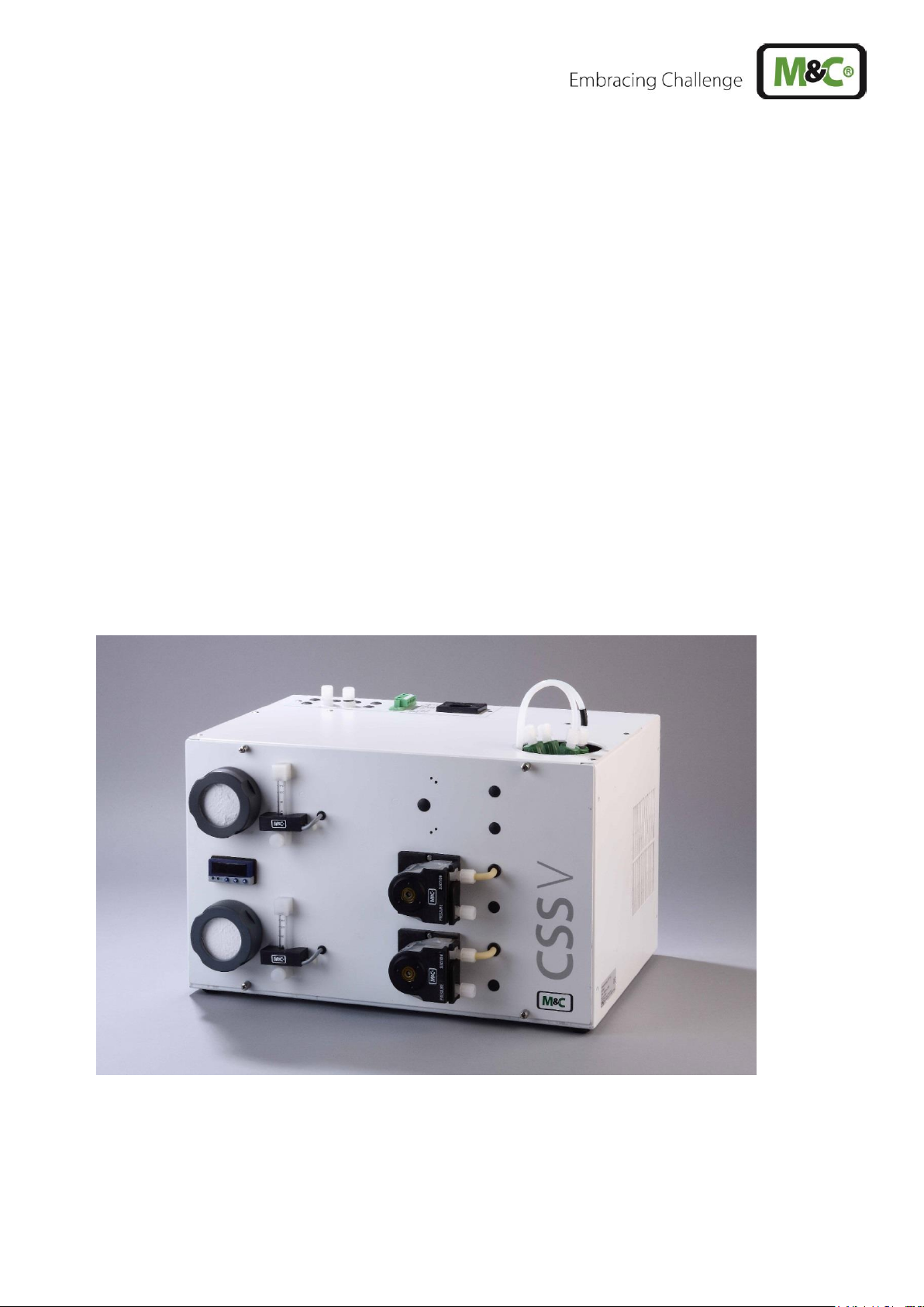
Gas Conditioning Unit Series CSS®
CSS-V1 and CSS-V2
19“ housing or wall mounting
Instruction Manual
Version 1.01.02
Page 2

2 CSS-V | 1.01.02 www.mc-techgroup.com
Dear customer,
Thank you for buying our product. In this manual you will find all necessary information about this M&C
product. The information in the manual is fast and easy to find, so you can start using your M&C product
right after you have read the manual.
If you have any question regarding the product or the application, please don’t hesitate to contact M&C
or your M&C authorized distributor. You will find the addresses in the appendix of this manual.
For additional information about our products and our company, please go to M&C’s website
www.mc-techgroup.com. There you will find the data sheets and manuals of our products in German
and English.
This Operating Manual does not claim to be complete and may be
subject to technical modifications.
© 03/2019 M&C TechGroup Germany GmbH. Reproduction of this
document or its content is not allowed without permission from M&C.
CSS® is a registered trade mark.
Version: 1.01.02
Page 3

www.mc-techgroup.com CSS-V | 1.01.02 3
List of Contents
1 General information .................................................................................................................... 5
2 Declaration of conformity ........................................................................................................... 5
3 Safety instructions ...................................................................................................................... 6
4 Warranty ...................................................................................................................................... 6
5 Used terms and signal indications ............................................................................................ 7
6 Introduction ................................................................................................................................. 9
7 Application .................................................................................................................................10
8 Technical Data ............................................................................................................................12
8.1 Options .................................................................................................................................13
9 Description .................................................................................................................................14
10 Receiving and storing ............................................................................................................16
11 Installation instructions .........................................................................................................16
11.1 Retrofitting of the wall mount housing to a 19“-housing .........................................................17
12 Supply connections ...............................................................................................................17
12.1 Hose connections .................................................................................................................17
12.2 Relocate the connections to the back of the housing ............................................................18
12.3 Electrical connections ...........................................................................................................19
12.3.1 Connecting signal lines ..................................................................................................20
13 Commissioning ......................................................................................................................21
13.1 Cooler control .......................................................................................................................21
14 Closing down ..........................................................................................................................22
15 Maintenance ............................................................................................................................22
15.1 Replacement of the filter element and the O-Ring .................................................................23
15.2 Dismounting the sample gas pump for examination or maintenance .....................................24
15.3 Maintenance of the integrated peristaltic pump type SR 25.2 ................................................25
15.3.1 Changing the pump tubing .............................................................................................26
15.3.2 Changing contact pulleys and springs ............................................................................27
15.3.3 Reassembly of the driver ...............................................................................................28
15.3.4 Cleaning the pump head ................................................................................................29
15.3.5 Repair information ..........................................................................................................29
15.4 Cleaning the cooling fins of the compressor cooler ...............................................................29
16 Operating of the integrated electronic temperature regulator ............................................30
16.1 Changing the set value .........................................................................................................30
17 Trouble shooting ....................................................................................................................31
18 Spare part list .........................................................................................................................33
19 Appendix .................................................................................................................................35
Page 4

4 CSS-V | 1.01.02 www.mc-techgroup.com
List of Figures
Figure 1 Gas flow diagram CSS-V1............................................................................................. 10
Figure 2 Gas flow diagram CSS-V2............................................................................................. 11
Figure 3 Design CSS-V2 ............................................................................................................. 14
Figure 4 Dimensions CSS-V1 and CSS-V2 ................................................................................. 15
Figure 5 Hose connections CSS-V1 ............................................................................................ 17
Figure 6 Connecting the collective alarm ..................................................................................... 20
Figure 7 Replacing the filter element and the O-ring ................................................................... 23
Figure 8 Dismounting the sample gas pump ............................................................................... 24
Figure 9 Changing the pump tubing ............................................................................................ 26
Figure 10 Different pump tube sizes .............................................................................................. 27
Figure 11 Disassembly of pump head and driver .......................................................................... 27
Figure 12 Check of axes and rolls ................................................................................................. 28
Figure 13 Front view of the temperature regulator ......................................................................... 30
Figure 14 Connecting conductors board CSS-V ............................................................................ 36
Page 5

www.mc-techgroup.com CSS-V | 1.01.02 5
Headquarters
M&C TechGroup Germany GmbH Rehhecke 79 40885 Ratingen Germany
Telephone: 02102 / 935 - 0
Fax: 02102 / 935 - 111
E - mail: info@mc-techgroup.com
www.mc-techgroup.com
1 GENERAL INFORMATION
The product described in this manual has been built and tested in our production facility.
All M&C products are packed to be shipped safely. To ensure the safe operation and to maintain the
safe condition, all instructions and regulations stated in this manual need to be followed. This manual
includes all information regarding proper transportation, storage, installation, operation and
maintenance of this product by qualified personnel.
Follow all instructions and warnings closely.
Read this manual carefully before commissioning and operating the device. If you have any questions
regarding the product or the application, please don’t hesitate to contact M&C or your M&C authorized
distributor.
2 DECLARATION OF CONFORMITY
CE - Certification
The product described in this operating manual complies with the following EU directives:
EMC-Instruction
The requirements of the EU directive 2014/30/EU “Electromagnetic compatibility“ are met.
RoHS Directive
The requirements of the RoHS2 (‘Restriction of Hazardous Substances 2’) directive 2011/65/EU and its
annexes are met.
Low Voltage Directive
The requirement of the EU directive 2014/35/EU “Low Voltage Directive“ are met.
The compliance with this EU directive has been examined according to DIN EN 61010.
Declaration of conformity
The EU Declaration of conformity can be downloaded from the M&C homepage or directly requested
from M&C.
Page 6

6 CSS-V | 1.01.02 www.mc-techgroup.com
3 SAFETY INSTRUCTIONS
Follow these safety directions and instructions regarding installation, commissioning and
operation of the device:
• Read this manual before commissioning and operating the product. Make sure to follow all safety
instructions.
• Installation and commissioning of electrical devices must be carried out only by qualified skilled
personnel in compliance with the current regulations.
• The installation and commissioning of the device must conform to the requirements of VDE 0100
‘Regulations on the Installation of Power Circuits with Nominal Voltages below 1000 V’ and must
be in compliance with all relevant regulations and standards.
• Make sure to compare the supply voltage with the specified voltage on the product label before
connecting the device.
• Protection against damages caused by high voltages:
Disconnect the power supply before opening the device for access. Make sure that all extern
power supplies are disconnected.
• Operate the device only in the permitted temperature and pressure ranges. For details please
refer to the technical data sheet or manual.
• Install the device only in protected areas, sheltered from rain and moisture. The product should
not be exposure to the elements.
• This device is NOT certified to be installed or operate in explosive hazardous areas.
• Installation, maintenance, inspections and any repairs of the devices must be carried out only by
qualified skilled personnel in compliance with the current regulations.
4 WARRANTY
In case of a device failure, please contact immediately M&C or your M&C authorized distributor.
We have a warranty period of 12 months from the delivery date. The warranty covers only appropriately
used products and does not cover the consumable parts. Please find the complete warranty conditions
in our terms and conditions.
The warranty includes a free-of-charge repair in our production facility or the free replacement of the
device. If you return a device to M&C, please be sure that it is properly packaged and shipped with
protective packaging. The repaired or replaced device will be shipped free of delivery charges to the
point of use.
Page 7
www.mc-techgroup.com CSS-V | 1.01.02 7
5 USED TERMS AND SIGNAL INDICATIONS
DANGER!
DANGER indicates a hazardous situation which, if not avoided, will
result in death or serious injury.
W AR N ING!
WARNING indicates a hazardous situation which, if not avoided,
could result in death or serious injury.
CAUTION!
CAUTION indicates a hazardous situation which, if not avoided,
could result in minor or moderate injury.
NOT I CE!
NOTICE is used to address practices not related to physical injury.
NOTE!
These are important information about the product or parts of the
operating manual which require user’s attention.
QUALIFIED PERSONNEL
‘Qualified personnel’ are experts who are familiar with the
installation, mounting, commissioning and operation of these types
of products.
High voltages!
Protect yourself and others against damages which might be caused
by high voltages.
Toxic!
Acute toxicity (oral, dermal, inhalation)! Toxic when in contact with
skin, swollowed or inhaled.
Corrosive!
These substances destroy living tissue and equipment upon contact.
Do not breathe vapors; avoid contact with skin and eyes.
Contains gas under pressure. Do not open container!
Check pressure before opening container, and adjust pressure to
atmosheric pressure.
Wear protective gloves!
Working with chemicals, sharpe objects or extremly high
temperatures requires wearing protective gloves.
Page 8

8 CSS-V | 1.01.02 www.mc-techgroup.com
Wear safety glasses!
Protect your eyes while working with chemicals or sharpe objects.
Wear safety glasses to avoid getting something in your eyes.
Wear protective clothes!
Working with chemicals, sharpe objects or extremly high
temperatures requires wearing protective clothes.
Page 9

www.mc-techgroup.com CSS-V | 1.01.02 9
6 INTRODUCTION
The gas conditioning units CSS-V1 and CSS-V2, optionally for 19" or wall mounting, are complete preassembled compact continuously operating gas conditioning systems, which, depending on the version,
can deliver a sample gas quantity of max. 2 x 150 Nl/h or 1 x 250 Nl/h. Due to a large number of
additional options, the sample gas preparation can be adapted to the various requirements of continuous
gas analysis technology.
The entire gas conditioning system is housed in a compact and robust sheet steel housing so that gas
analyses can be carried out quickly, with low maintenance and reliably without any major assembly
work.
The CSS-V1 and CSS-V2 gas conditioning units must not be used for sampling flammable gas/air or
gas/oxygen mixtures, for sampling flammable gas which can form an flammable mixture in combination
with air or oxygen, or in explosive atmospheres or in hazardous areas.
Page 10
10 CSS-V | 1.01.02 www.mc-techgroup.com
7 APPLICATION
The CSS-V1 and CSS-V2 are completely pre-installed sample gas conditioning systems for
continuous use, which can be excellently integrated into analytical systems due to their individual
configurability. The compact design only requires a small amount of space. The preparations are
ready for operation within a few minutes. The usual time-consuming procurement of individual
components and small parts and their assembly is no longer necessary.
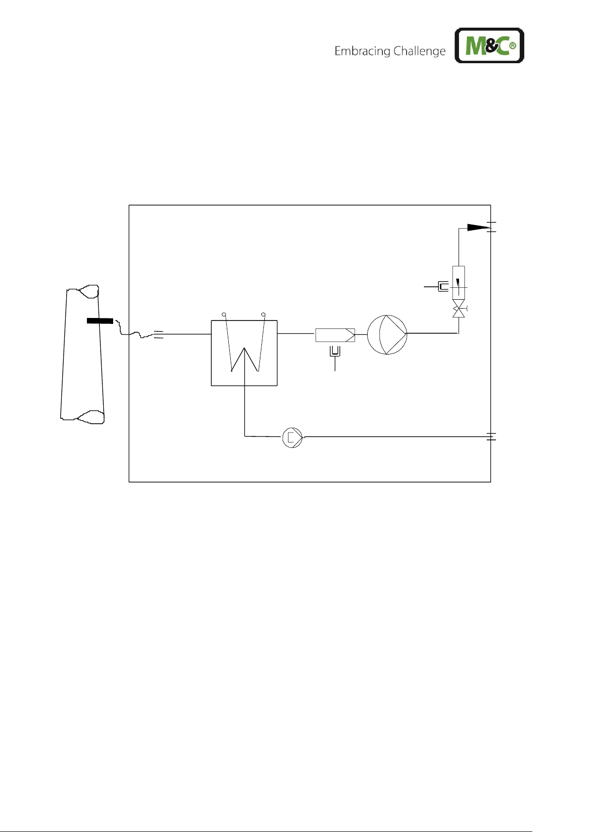
Figure 1 Gas flow diagram CSS-V1
Gas cooler ECM-1
Front panel filter FPF-2-0,3GF, 0.3 µm porosity with integrated liquid alarm sensor (optional)
Sample gas pump N3/5/9 KPE (optional)
Flowmeter FM40 with option flow alarm FM-20mo (optional)
Peristaltic pump SR25.2 for continuous automatic condensate removal (optional)
• Sample gas line, material: PTFE.
• Condensate line, material: Novopren®.
• At the heat exchanger the sample gas inlet and outlet are marked with arrows.
Page 11
www.mc-techgroup.com CSS-V | 1.01.02 11
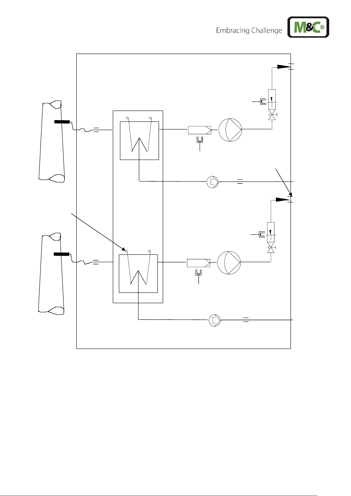
Figure 2 Gas flow diagram CSS-V2
Gas cooler ECM-2
2 x Front panel filter FPF-2-0,3GF, 0.3 µm porosity with integrated liquid alarm sensor (optional)
2 x Sample gas pump N3/5/9 KPE (optional)
2 x Flowmeter FM40 with 2 x flow alarm FM-20mo (optional)
2 x Peristaltic pump SR25.2 for continuous automatic condensate removal (optional)
• Sample gas line, material: PTFE.
• Condensate line, material: Novopren®.
• To distinguish the sample gas lines, sample gas line 2 is marked with a black O-ring at the sample
gas inlet and outlet of the heat exchanger 2.
• At the heat exchanger, sample gas inlet and outlet are marked with arrows.
Marking with
black O-ring
Marking with
black O-ring
Page 12

12 CSS-V | 1.01.02 www.mc-techgroup.com
8 TECHNICAL DATA
Gas Conditioning Unit Type
CSS-V1
CSS-V2
Part No. 230 V/50 Hz
01G6010
01G6020
Part No. 115 V/50 to 60 Hz
01G6010a
01G6020a
Sample outlet dew point
Adjustment range 2 to 7 °C [35.6 to 44.6 °F], factory setting
+5 °C [41 °F]
Dew point stability
At constant conditions < ±0.1 °C [±0.18 °F]
Sample inlet temperature
Max. 180 °C** [356 °F**]
Gas inlet water vapor saturation
Max. +80 °C** [176 °F**]
Gas flow rate
**Max. 250 Nl/h
**Max. 2 x 150 Nl/h
Ambient temperature
+10 to +40 °C** [50 to 104 °F**]
Storage temperature
-25 to +65 °C [approx. -13 to 149 °F]
Pressure
0.7 bar to 1.4 bar abs.*
Total cooling capacity
Max. 144 kJ/h
Number of gas inlets
1
2
Number of gas outlets
1
2
Number of condensate outlets
1
2
Sample gas connections
Tube connection 4/6 mm
Material of sample contacting parts
PVDF, PVC, Novoprene®, FPM, PPH, PTFE
Ready for operation
Approx. 10 min.
Mains power supply
230 V 50 to 60 Hz ±10 % or 115 V 50 to 60 Hz ±10 %
(115 V/50 Hz not with option sample pump)
Power consumption
Max. 220 VA + max: 300 VA for the sample gas pumps
Fuse protection
6.3 A, time-lag, 5 x 20 mm
Electrical mains supply
Cold appliance plug with 2 m [6.56 ft] cable
Case protection
IP20 EN 60529
Housing version
Sheet steel case for 19”- or wall mounting, lacquered
RAL 7035
Case dimensions (W x H x D)
483 x 267.5 x 301.5 mm [19” x 10.5” x 11.9”]
Weight
Approx. 22 kg [48.5 lbs]
PVDF = Polyvinylidenefluoride
PVC = Polyvinyl chloride
FPM = Fluor caoutchouc
PPH = Polypropylene hard
PTFE = Polytetraflourethylene
* Standard
** Maximum values in technical data must be rated in consideration of total cooling capacity at 25 °C
[77 °F] ambient temperature and 5 °C [41 °F] outlet dewpoint.
Page 13
www.mc-techgroup.com CSS-V | 1.01.02 13
8.1 OPTIONS
Part No.
Description
93K0140
Extra charge for heat exchanger ECM- 1, material: glass
93K0170
Extra charge for heat exchanger ECM- 1 material: stainless steel SS 316Ti
93K0160
Extra charge for heat exchanger ECM- 1 material: PVDF
97K0100
Extra charge for heat exchanger ECM- 2 material: glass
97K0110
Extra charge for heat exchanger ECM- 2 material: stainless steel SS 316Ti
97K0115
Extra charge for heat exchanger ECM- 1 material: PVDF
01G6125
Extra charge for mounting a sample gas pump N3 KPE
(additionally electronic controller 01G6150 necessary)
01G6130
Extra charge for mounting a sample gas pump N5 KPE
(additionally electronic controller 01G6150 necessary)
01G6135
Extra charge for mounting a sample gas pump N9 KPE
(additionally electronic controller 01G6150 necessary)
01G6120
Extra charge for mounting a sample gas filter FPF-2-0,3GF with integrated liquid
alarm sensor
09F4000
Extra charge for mounting a flow meter FM40 7 to 70 Nl/h
09F4005
Extra charge for mounting a flow meter FM40 15 to 150 Nl/h
09F4010
Extra charge for mounting a flow meter FM40 25 to 250 Nl/h
02E3500
Extra charge for mounting a flow alarm sensor FA-20mo
01G6150
Extra charge for mounting a control electronic for max. 2 liquid alarm sensors and
max. 2 flow alarm sensors
01P9125
Extra charge for mounting a peristaltic pump SR25.2 for condensate removal, with
complete tubing
Page 14

14 CSS-V | 1.01.02 www.mc-techgroup.com
9 DESCRIPTION
Figure 3 Design CSS-V2
Fine filter FPF-2-0,3GF
Electronic controller
Flow meter FM40 with flow alarm sensor FA-20mo
Peristaltic pump SR25.2 with condensate outlet
Cold appliance socket
Connection for collective alarm
Sample gas outlets
Condensate outlet directly at the peristaltic pump
Sample gas inlet directly at the heat exchanger
All components of the gas conditioning unit are mounted inside a compact sheet steel case. Filter and
peristaltic pump are mounted to the front panel to ensure easy maintenance.
The minimum flow is determined by the gas sample pump (see also chapter 8) Premature damage can
be caused to the pump membrane if less than the minimal total amount of flow is extracted as a result
of excess pressure.
The gas cooler is equipped with a heat exchanger made of Duran glass, stainless steel SS 316Ti or
PVDF.
The FPF-2-0.3GF fine filter (0.3 µm filter porosity) installed upstream of the N3/5/9 KPE sample gas
pump ensures the necessary solids separation.
Page 15

www.mc-techgroup.com CSS-V | 1.01.02 15
The instrument contains a temperature alarm contact that is activated in case the temperature differs
more than ±3 °C [±5.4 °F] from the set value (+ 5 °C [41 °F]) adjusted at the factory and switches off the
sample gas pump if existing. The temperature alarm contact of the cooler ( +8 °C or +2 °C) [ 46.4 °F
or 35.6 °F] (controls automatically the switching on and off of the sample gas pump.
The condensate occurred is removed continuously via the peristaltic pump type SR25.2.
The DN4/6 mm hose connections for the sample gas outlet as well as the electrical connections in the
top of the gas conditioning unit can, in dependence on the installation conditions, also be mounted in
the back of the unit very easily.
The ventilation grids in the sidewalls ensure that the equipment is sufficiently ventilated.
A liquid alarm sensor is integrated in the filter FPF-2-0,3GF to protect the downward analysers against
liquid irruptions and to increase the operating safety of the whole system. In case of liquid inrush, the
sample gas pump, if existing, is switched off automatically.
Figure 4 Dimensions CSS-V1 and CSS-V2
Page 16

16 CSS-V | 1.01.02 www.mc-techgroup.com
10 RECEIVING AND STORING
The gas sampling systems CSS-V1 and CSS-V2 are completely pre-installed unit. The scope of delivery
includes furthermore:
• 25 x Filter elements (1 package)
• 1 x Connection cable
• 1 x 6-pole connection box
• 1 x Instruction Manual
Please remove the CSS-V1 or CSS-V2 carefully from the packaging. Check the scope of the delivery
specified on the delivery note. Please make sure that you have received all items stated on the delivery
note.
Please check the unit for any transport damages after receipt and report any complaints to the transport
company immediately.
NOTE!
The gas conditioning system should be stored in a protected frost-free area!
11 INSTALLATION INSTRUCTIONS
NOTE!
In order to ensure that the case is safe and stable when being used, it should
be placed on a horizontal surface free from vibrations. Only then, the perfect
functioning of the separation and drainage procedures of the condensate
inside the heat exchanger of the cooler will only be guaranteed.
The gas conditioning system should be kept away from heat sources and be
freely ventilated in order to prevent an accumulation of heat.
When the equipment is being used outside, ample protection against the
effects of direct sunlight and dampness must be provided. In winter, the
equipment must only be used in frost-free areas; pay attention to the type of
the equipment protection.
Please avoid temperature variations, strong airflow as well as aggressive
atmospheres at the place of installation.
In order to guarantee the operational safety of the gas conditioning system
and the downstream analysers, and to avoid false alarms, the gas conditioning
unit should not be used at temperatures other than those specified.
Furthermore, it must be protected against dust deposits and penetrating dust.
It is of great importance that the analysers connected downstream are used at
temperatures well above the specified gas outlet dew point of +5 °C [41 °F].
This prevents the gas in the connector lines to the analysers from subsequent
condensing.
Unheated gas sample lines must be installed with slope up to the cooler.
Page 17

www.mc-techgroup.com CSS-V | 1.01.02 17
11.1 RETROFITTING OF THE WALL MOUNT HOUSING TO A 19“-HOUSING
The gas conditioning units CSS-V1 and CSS-V2 are delivered with a wall mounting housing.
If a 19”-housing is needed, the gas conditioning unit can be retrofitted very easy by installing the
mounting brackets from the back to the front:
• Remove two fixing screws per bracket,
• Align the angle with the 19" mounting holes facing the front,
• Fix the mounting bracket flush with the front panel at the housing by using the two fixing screws.
12 SUPPLY CONNECTIONS
12.1 HOSE CONNECTIONS
Figure 5 Hose connections CSS-V1
NOTE!
Do not mix up the hose connections.
Check the seals after connecting all lines.
Contrary to Figure 5, version CSS-V2 has two sample gas outlets.
The condensate connections are carried out directly at the peristaltic pump.
All tube connections are DN 4/6 mm sealing ring threaded hose couplings out of PVDF/PPH as standard.
They are suitable for gas inlet temperatures of maximum 80 °C [176 °F] (see chapter 8).
Page 18

18 CSS-V | 1.01.02 www.mc-techgroup.com
Follow these steps to mount the sample gas and condensate tubes:
• Remove the union nut from the sealing ring couplings by turning it anti-clockwise. Be sure to remove
the union nut carefully from the fitting. There is a loose clamp ring inside the union nut.
• Place the union nut over the connecting tube.
• Push the sealing ring over the connecting tube with the thicker bulge facing the nut.
• Place the tube over the nipple on the thread.
NOTE!
The tightness of the connections can only be guaranteed if the connecting
tube has a straight edge (use a hose cutter).
• Hand-tighten the nut.
The tube is now slip-proof and pressure-tight mounted to the hose connection fitting.
The tubes are to be removed in the reverse order.
W AR N ING!
Aggressive condensate is possible.
Chemical burns caused by aggressive media possible!
Wear protective gloves and protective glasses!
Wear proper protective clothing!
12.2 RELOCATE THE CONNECTIONS TO THE BACK OF THE HOUSING
If the installation conditions require to relocate the connections to the back of the housing, follow these
steps:
• Remove connection sheet fixing screws (see Figure 5)
• Remove cover angle fixing srews at the back of the unit
• Attach connection sheet with 2 fixing screws at the back of the unit
• Attach cover angle with 2 fixing screws at the top of the housing
Page 19

www.mc-techgroup.com CSS-V | 1.01.02 19
12.3 ELECTRICAL CONNECTIONS
W AR N ING!
Wrong supply voltage can damage the equipment. When connecting
the equipment, please ensure that the supply voltage is identical
with the information provided on the model type plate!
NOTE!
For the assembly of power installations with rated voltages up to
1000 V, the requirements of VDE 0100 and relevant standards and
specifications must be observed!
The main circuit is equipped with a fuse corresponding to the
nominal current (over current protection); for electrical details see
technical data (chapter 8).
The gas conditioning units CSS-V1 and CSS-V2 are available with either 230 V/50 Hz or 115 V/50 to
60 Hz (for circuit diagram see appendix). 6.3 A time-lag fuses are used on all models as fuse protection.
The fuses are located inside of the cold appliance socket.
The electrical connection is made via the 2 m [6.56 ft] mains cable with cold appliance plug optionally at
the back side or the top of the housing.
Page 20

20 CSS-V | 1.01.02 www.mc-techgroup.com
12.3.1 CONNECTING SIGNAL LINES
The electrical connection of the collective alarm (cooler, liquid and flow) is a 6-pole male connector,
which is located at the back or top of the housing.
The matching 6-pole female connector is part of the scope of delivery.
The male connector is connected as follows:
Figure 6 Connecting the collective alarm
For CSS-V1 the collective alarm of the lower channel is connected (4, 5, 6).
For CSS-V2 both channels are connected with the cooler alarm and with one liquid and one flow alarm
each.
NOTE!
Please install the signal lines separated from the power supply
lines.
1
2 3 4 5 6
Intern
Extern
Status Alarm
Kontaktbelastung
Contact rating
24 V AC/DC 0.5 A
Stecker/male connector Typ Phoenix MSTB
2,5/6-STF 5,08
Oberer Kanal
Unterer Kanal
Buchse/Female X2
Lower channel
Upper channel
Page 21

www.mc-techgroup.com CSS-V | 1.01.02 21
13 COMMISSIONING
Before commissioning, the plant-specific and process-specific safety measures must be observed.
Before switching on the power supply, check again that the operating voltage (see type plate) and the
mains voltage match!
Follow these steps before starting up the device for the first time:
• Place the cold appliance plug, which is delivered with the mains supply cable, into the cold appliance
plug socket;
• Connect the mains plug to the mains;
• Switch on power.
After the starting time (LED K1 on the controller is on), the gas conditioning system is ready for use, and
the sample gas pump is switched on. Only now the sample gas can be fed.
NOTE!
The following minimum gas flow rates result from the requirement not to limit
the sample gas pump to less than 20 % of its maximum capacity:
N3 KPE min. 30 Nl/h air
N5 KPE min. 60 Nl/h air
N9 KPE min. 110 Nl/h air
If the required minimum total flow rate is not reached, excessive overpressure
can lead to premature destruction of the pump diaphragm.
For long-term measurements with a high dust content in the sample gas, a
suitable gas sampling probe must be provided to protect the sampling line
from blockages.
13.1 COOLER CONTROL
Indication
LED K1
LED K2
After starting up
> 8 °C [> 46.4 °F]
(Ambient
temperature)
Off (Status alarm and pump
off)
Yellow light is
permanently on
(cooling)
After approx. 10 min.
7.5 °C [ 45.5 °F]
Yellow light is on
If there is no condensate
alarm, the pump is switched
on.
Sample gas is pumped.
Yellow light is
permanently on
(cooling)
Normal operation
5 °C [41 °F]
Yellow light is on
Yellow light is blinking
(cooler control)
Page 22
22 CSS-V | 1.01.02 www.mc-techgroup.com
14 CLOSING DOWN
NOTE!
The location for the gas conditioning unit must remain frost-free, even if the
unit has been switched off.
There are no special regulations to be observed if the gas conditioning unit CSS-V1 or CSS-V2 is to be
closed down for a short period of time.
In the event of prolonged shutdown, it is recommended to purge the gas conditioning system with
ambient air or inert gas. A flushing time of 3 to 5 minutes is sufficient under normal conditions.
Condensate residues must also be removed from the system.
W AR N ING!
Aggressive condensate is possible.
Chemical burns caused by aggressive media possible!
When disassembling, repairing or cleaning, wear safety glasses and
proper protective clothing!
15 MAINTENANCE
Before carrying out maintenance work, the plant-specific and process-specific safety measures must be
observed!
W AR N ING!
Dangerous voltage. Before any maintenance work is carried out on
the gas conditioning system, disconnect the unit from the mains!
The frequency of the maintenance work depends on the operational process and can therefore only be
determined in each individual case.
All parts which require maintenance work are easily accessible and are installed on the front side of the
gas conditioning unit CSS-V1 or CSS-V2. The housing must only be opened for maintenance of the
sample gas pump:
• Replace the filter element of the fine filter FPF-2-0,3 GF in case the flow rate is too low or after visible
inspection (see chapter 15.1).
Page 23

www.mc-techgroup.com CSS-V | 1.01.02 23
NOTE!
In order to protect downstream analyzers, the wet filter element must
always be replaced in the event of a condensate ingress.
• The diaphragm of the sample gas pump N3/5/9 KPE should be checked every six months and, if
necessary, replaced (see chapter 15.2).
• The hose of the condensate pump SR25.2 should be checked every six months and, if necessary,
replaced (see chapter 15.3.1);
• Remove dust periodical from the cooling fins with pressure air (see chapter 15.4)
15.1 REPLACEMENT OF THE FILTER ELEMENT AND THE O-RING
NOTE!
In any case you open the filter, the filter element has to be changed.
For changing the filter element and the O-ring:
• Disconnect the mains voltage
• Unscrew the filter housing cover
• Exchange the filter element and/or O-ring. Pay attention to the correct insertion of the filter
element and the O-ring (the textured surface of the filter element points to the front)!
• Screw on the filter housing cover again.
Figure 7 Replacing the filter element and the O-ring
Page 24

24 CSS-V | 1.01.02 www.mc-techgroup.com
15.2 DISMOUNTING THE SAMPLE GAS PUMP FOR EXAMINATION OR MAINTENANCE
For dismounting the sample gas pump N3/5/9 KPE:
W AR N ING!
Dangerous voltage. Before any maintenance work is carried out on
the gas conditioning system, disconnect the unit from the mains!
• Disconnect the gas conditioning system from the mains voltage
• Loosen the 4 screws on the front panel and slightly open it to the front without removing the tubing
and wiring and pull it upwards out of the housing holder.
• Loosen the 4 fastening screws of the mounting angle on which the pump is mounted (Figure 8)
• Remove tubing from the pump head
• Pull out the pump with mounting angle
• Inspection and maintenance according to operating instructions N3/5/9 KPE (is part of the
supplied manual or can be downloaded from our homepage: www.mc-techgroup.com)
• After inspection or maintenance, retighten the mounting bracket and mount the front panel
fixing screws
mounting angle
Figure 8 Dismounting the sample gas pump
Page 25

www.mc-techgroup.com CSS-V | 1.01.02 25
15.3 MAINTENANCE OF THE INTEGRATED PERISTALTIC PUMP TYPE SR25.2
Before starting any maintenance work, make sure that any work done on the device is in compliance
with all relevant regulations and standards.
W AR NING !
Inhalation hazard possible, if using toxic or asphyxiant gases!
Purge peristaltic pump with inert gas or air before opening! If the
pump is used for toxic gas or asphyxiant (oxygen-displacing) gas,
it needs to be purged with inert gas or air before opening. Follow
closely all relevant occupational safety regulations during
operation.
W AR NING !
Disconnect power supply before opening the device for access.
Make sure that all external power supplies are disconnected.
Aggressive condensate possible!
Media residues in tubing!
Chemical burns caused by aggressive media possible!
Wear protective gloves and protective glasses!
Wear proper protective clothing!
Peristaltic pump is under pressure! Do not open housing!
A peristaltic pump might be part of a system, which is under
pressure. Check pressure before opening peristaltic pump, and
adjust pressure to atmosheric pressure.
Flexible tube, conveying belt, contact pulleys and contact springs are the only parts of the pump subject
to wear. They are simple to change.
NOTE!
If you send back the peristaltic pump to the M&C service for repair,
please let us know what kind of condensate has been pumped.
Before sending the pump back clean all parts from dangerous or highly
aggressive contaminants.
Page 26
26 CSS-V | 1.01.02 www.mc-techgroup.com
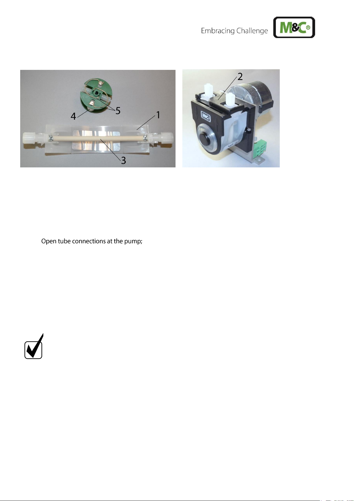
15.3.1 CHANGING THE PUMP TUBING
1 Conveying belt
2 S-bolt
3 Tubing set
4 contact pulley
5 springs
Figure 9 Changing the pump tubing
For changing the pump tubing please proceed as follows:
• Unplug the pump from the mains voltage. The device needs to be voltage free.
•
• Press conveying belt at the recessed grips and turn S-bolt clockwise up to limit stop;
• Take away conveying belt and remove the old tubing set from the guides by pulling on the
tube connectors;
• Press the two contact pulleys and check whether the spring pressure is still sufficient, if not,
the contact springs have to be changed (see chapter 15.3.2);
• Put the new tubing set with the tube connectors into the guides of the conveying belt ;
NOTE!
Only the usage of the original tubing set guarantees a proper functionality.
Never lubricate the tube.
Before mounting the pump check all parts for contaminations and clean if
necessary.
• Put the conveying belt with the new tubing into the dovetail guide of the pump body;
• Press conveying belt at the recessed grips and simultaneously turn the S-bolt anticlockwise
until it snaps;
• Switch on pump.
Page 27

www.mc-techgroup.com CSS-V | 1.01.02 27
Figure 10 Different pump tube sizes
15.3.2 CHANGING CONTACT PULLEYS AND SPRINGS
NOTE!
While mounting, make sure that the center of rotation and the driver
are aligned.
Use genuine spare parts only!
Follow these instructions to change the contact pulley and springs:
• Disconnect the peristaltic pump from power supply
• Unscrew nuts of the pump head (wrench size 5.5)
1 Pump head nuts
2 Pump head
3 Springs
4 Groove
5 Driver (roll carrier)
6 Collar of the shaft bore
Figure 11 Disassembly of pump head and driver
• Remove the pump head from the motor shaft
• Now the driver can be removed from the pump head and is ready for maintenance
• The removal of the springs 4 pcs.) away from the driver is easily possible without the aid of
any tools. For this take spring out of the groove near to the shaft bore
Page 28

28 CSS-V | 1.01.02 www.mc-techgroup.com
• Dismount roller axes and change contact pulleys. Take care that axes are not worn out by the
springs and have damaged the dent at the axes front end. In case of abrasion the axes have to
be changed (see Figure 12).
Figure 12 Check of axes and rolls
NOTE!
The springs may come in different colorings. This is not a quality
impairment. Make sure to use the right spring strength. This can be
identified by the spring wire diameter. The ‘standard version for
Novoprene pump tubing’ (Part No. 90P1010) has a diameter of 1.1 mm and
the ‘reinforced version for FPM-, Acidflex- or Masterflex-tubing’ (Part No.
90P1015) has a diameter of 1.2 mm.
NOTE!
Two different types of springs are mounted inside the driver (right and left
springs) for the first delivery. When spare springs are ordered, for
simplified storage, only one type will be delivered (right spring) which can
be used for all four springs and will replace without any problems the
initial springs. The replacement springs guarantee full functionality when
all four springs are replaced.
• Make sure that contact pulleys move easily on the axis. After remounting the axis with contact
pulley into the driver the spring has to be mounted as shown as in Figure 12. Please pay attention
to the alignment of the dent.
15.3.3 REASSEMBLY OF THE DRIVER
Reassemble the driver in reverse order:
• Insert the roll carrier back into the pump head
• Push the pump head with the roll carrier onto the motor shaft
• Tighten the nuts of the pump head fastening (SW 5.5) .
The dent prevents
rotation of the axis
new
worn out
Page 29
www.mc-techgroup.com CSS-V | 1.01.02 29
NOTE!
While mounting, make sure that the center of rotation and the roll carrier
(driver) are aligned.
Make sure that the collar of the shaft bore (see Figure 11) faces towards
the front of the pump head while mounting the roll carrier.
Use genuine spare parts only!
15.3.4 CLEANING THE PUMP HEAD
When changing flexible tube or other parts, inspect all parts for dirt before assembling the pump head
and clean them if necessary.
We recommend to clean the parts with a dry cloth. Solvent should not be used, because it can
damage the plastics and synthetic rubber parts. Use oil-free compressed air to clean the parts if
available.
Aggressive condensate possible!
Media residues in tubing!
Chemical burns caused by aggressive media possible!
Wear protective gloves and protective glasses!
Wear proper protective clothing!
15.3.5 REPAIR INFORMATION FOR INTEGRATED PERISTALTIC PUMP TYPE SR25.2
NOTE!
When sending the peristaltic pump to M&C customer service for repair,
please indicate the type of medium pumped. Before shipping the pump,
please remove hazardous or aggressive contaminations from all parts of
the pump!
15.4 CLEANING THE COOLING FINS OF THE COMPRESSOR COOLER
To prevent a decrease of the cooling capacity the cooling fins have to be cleaned from dust periodical.
For this purpose blow compressed air into the ventilation grid at the right side of the housing.
NOTE!
With clean cooling fins a DIN A4 sheet of paper is sucked in and
clings to the right side of the housing.
Page 30

30 CSS-V | 1.01.02 www.mc-techgroup.com
16 OPERATING OF THE INTEGRATED ELECTRONIC TEMPERATURE REGULATOR
During normal operation, the display of the temperature regulator shows the actual cooling temperature.
Figure 13 Front view of the temperature regulator
16.1 CHANGING THE SET VALUE
For changing the set value, press the P-button < 2 s. The set value, adjusted at the factory to 5 °C
[41 °F], is shown. With both arrow keys, the set value can be set upwards or downwards. However, this
value should not be adjusted below +2 °C [35.6 °F], otherwise freezing up of the heat exchanger is
possible. If the value is set above ambient temperature, the cooler will not work.
Page 31
www.mc-techgroup.com CSS-V | 1.01.02 31
17 TROUBLE SHOOTING
The following table shows possible sources of errors and how to remove them (not applicable for the
starting-up phase).
Display
Fault
Possible cause
Examination/Correction
None
No supply voltage;
Check the supply voltage according to the type
plate;
ok?
Control whether the mains plug is put in correctly;
ok?
Examine the fine fuses F1, F2 in the cold appliance
socket;
ok?
LED K1 is
beaming
permanently and
temp. > 8 °C
[> 46.4 °F]
Cooler alarm „Excess
temperature“; cooler
switches off the
sample gas pump
automatically if
existing;
Ventilator does not
function
Ambient temperature too high;
ok?
Free convection inside the gas conditioning unit
upset internal temperature too high;
ok?
Sample flow or dew point too high? Reduce flow.
ok?
Return the instrument for repair to M&C.
Temp.
> 2 °C
[> 35.5 °F] and
< 7.5°C
[< 45.5 °F]
Cooler runs,
sample flow is
interrupted;
Pump
defective
Diaphragm pump
does not work;
Liquid alarm sensor:
Sensor turns sample
gas pump
automatically off;
LED Liquid alarm is beaming red.
Liquid in the filter (Dry filter and liquid alarm sensor
and check peristaltic pump, see below.)
ok?
Check the tubing for condensate draining;
ok?
Check pump tubing (see 15.3.1)
ok?
Check pump SR25.2 (see 15.3);
ok?
Return instrument for repair to M&C.
Page 32

32 CSS-V | 1.01.02 www.mc-techgroup.com
Display
Fault
Possible cause
Examination/Correction
Pump works,
but sample
gas flow is
interrupted;
Flow meter :
Needle valve is shut.
Sample probe or
sample hose clogged
or line squeezed;
Sample line to the
analyser clogged or
squeezed;
Pollution of the
diaphragm pump;
Set the desired flow rate on the needle valve.
Loosen the sample hose from the sample gas inlet
of the gas conditioning unit (see 12.1);
Gas flow?
Clean the clogged line or replace it;
No gas flow?
Loosen the outlet hose on the analyser side and
check on the threaded hose coupling whether
sample gas flows;
Sample gas does not flow?
Clean the clogged line or replace it;
Sample gas flows?
ok?
Loosen the piping on the pump head and examine it
(see 15.2);
ok?
If necessary, clean the pump;
Ok?
Temp.
< 2 °C
[< 35.6 °F]
Cooler switches off
the sample gas pump
automatically;
Cooler defective;
Ambient temperature too low;
ok?
Return the instrument for repair to M&C.
Page 33

www.mc-techgroup.com CSS-V | 1.01.02 33
18 SPARE PART LIST
Wear, tear and replacement part requirements depend on specific operating conditions.
The recommended quantities are based on experience and are not binding.
Gas Conditioning Unit Version CSS-V
(V) Consumables, (E) Recommended Spare Parts and (T) Spare Parts
Recommended quantity after
operation of [years]
Part No.
Description
C/R/S
1 2 3
Fine filter FPF-2-0,3GF
90F0160
Filter element type F-2-0,3GF. Material: glass
fiber, porosity: 0.3 µm 25 pcs./pack.
C 1 2
3
90F0167
O-ring FPF-2/54. Material: Viton.
R 1 1
1
Peristaltic pump SR25.1:
90P1007
SR25 pump hose with threaded hose
coupling of PVDF, DN 4/6 mm
C 1 2
4
90P1010
1 set contact spring for driver of peristaltic
pump R25.2, (set = 4 pcs.)
C 1 2
3
90P1020
Driver complete for peristaltic pump SR25.2
R
1
90P1045
Contact pulley (1 pc.) for peristaltic pump
SR25.2, (2 pcs./pump required).
C 2
4
Diaphragm pump type N3/5/9 KPE
90P2100
Square cap type D3, 1/8“i for
N3/N5 KPE/KP18. Material: PVDF
S - -
1
90P2120
Diaphragm type S3, for N3/N5 KPE/KP18,
Material: Viton, PTFE coated
C 1 2
3
90P2111
Valve reed type V3 with O-ring type O3, for
N3-N5, 1 pc, material: Viton (2 pieces per
pump required)
C 2 4
6
90P2105
Intermediate plate type Z3, for
N3/N5 KPE/KP18, Material: PVDF
S - -
1
90P2220
Diaphragm type S9, for N9 KPE/KP18,
Material: Viton, PTFE coated
C 1 2
3
90P2211
Valve plate with seal for N9 KPE, 1 piece,
material: Viton. (2 pieces per pump required)
C 2 4
6
90P2205
Intermediate plate type Z9, for
N9 KPE/KP18, Material: PVDF
S - -
1
90P2200
Square cap type D9, 1/8“i for
N9 KPE/KP18. Material: PVDF
S - -
1
Flow meter FM40:
90A0015
Flow meter glass for FM40
Measuring range 7-70 Nl/h air
S - 1
1
94F0010
Flow meter glass for FM40
Measuring range 15-150 Nl/h air
S - 1
1
Page 34

34 CSS-V | 1.01.02 www.mc-techgroup.com
Gas Conditioning Unit Version CSS-V
(V) Consumables, (E) Recommended Spare Parts and (T) Spare Parts
Recommended quantity after
operation of [years]
Part No.
Description
C/R/S
1 2 3
94F0015
Flow meter glass for FM40
Measuring range 25-250 Nl/h air
S - 1
1
90A0018
Viton O-ring 9 for FM40 glass
R 2 4
6
Miscellaneous:
90G0030
Fine fuse 6.3 A T, 5 x 20 mm for CSS-V1 and
CSS-V2
R 5 5
5
Tube and threaded tube couplings:
05V3215
Bulkhead union SV-PVDF DN 4/6
R 2 2
2
05V6600
Ferrule 4/6 PVDF s.a.
R 5 10
10
05V6605
Union nut M10-4/6 PVDF s.a.
R 5 10
10
01T1000
Viton tube NW 4/6 (m)
S 1 2
3
10T1000
Hose cutter
S 1 1
1
Page 35

www.mc-techgroup.com CSS-V | 1.01.02 35
19 APPENDIX
• Connecting conductors board CSS-V
For further product documentation, please see our internet catalogue:
www.mc-techgroup.com
• Instruction manual peristaltic pump SR25.1
• Instruction manual diaphragm pump series N
• Flowmeter FM 40,
Data sheet : 9.2
Page 36
36 CSS-V | 1.01.02 www.mc-techgroup.com
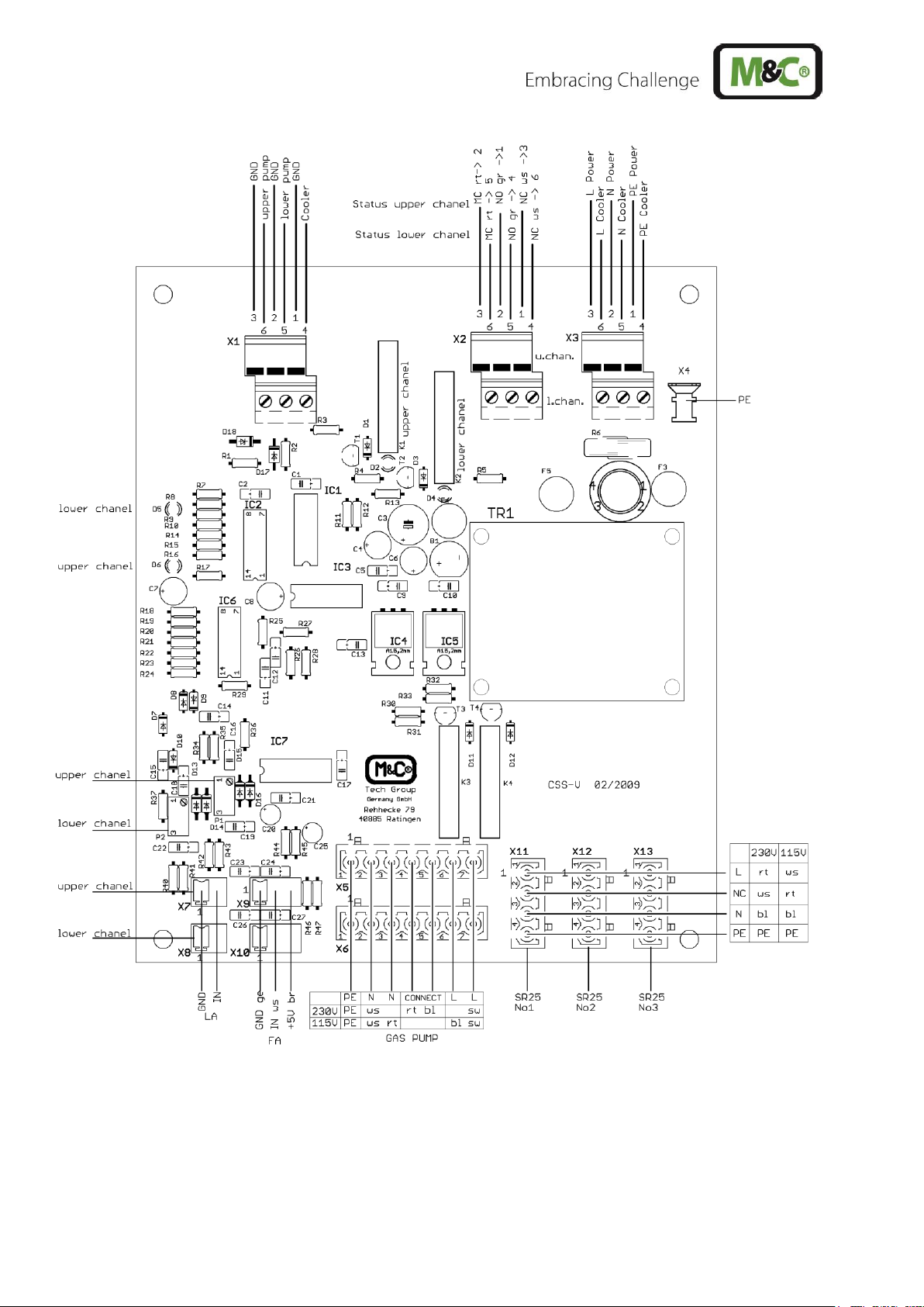
Figure 14 Connecting conductors board CSS-V
 Loading...