

MBS UBR-01 MK II, UBR-02 User Manual
MBS Universal BACnet Router
User Guide
UBR-01 | MK II & UBR-02
+24
GND
B+
A-
Shld
AGND
Reset
UBR-01 | MK II
Universal Gateway
Status
Power
MS/TP
LAN
B+
–
PWR
+
A-
GND
S3
S2
S1
TX
RX
B+
A-
Shld
AGND
+24
GND
B+
A-
GND
TXD
RXD
GND
MSTP COM3
RS232
RS232 COM2
RS485
TX
RX
TX
RX
TXD
RXD
GND
LAN
2
B+
A-
GND
S3
S2
S1
LAN
1
B+
–
PWR
+
A-
GND
S3
S2
S1
TX
RX
ST.
PWR.
Reset
UBR-02
BACnet Router

Table of Contents
4 Foreword
4 Registered trademarks
4 Copyright
5 Product support
5 Note on disposal
6 MBS Universal BACnet Router (UBR)
6 Schematic view of a typical BACnet network
7 MBS UBR type overview
7 Routing options
8 Further characteristics of the MBS Universal BACnet Routers
9 Casing and connections
10 Device views
10 UBR-01 | Mk II front view
11 UBR-02 front view
12 Side view
12 Top
12 Rear
13 Start-up and operation
13 Power unit for the UBR
13 Hardware installation
13 Assembly
13 Electrical installation
14 Ethernet network installation
14 MS/TP network installation
14 Configuring the router using the web interface
14 Opening the web interface
15 Logging on to the web server
16 Web server language
16 "General" area
16 General > overview
17 General > information
18 General > IP network

33
20 General > system time
21 General > User
23 General > data backup
24 General > Update
25 General > Restart
27 "BACNET" area
27 BACnet > Settings
36 BACnet > device object
38 BACnet > Network Security (for UBR-02 ONLY)
41 "Diagnostics" area
41 Diagnosis > statistics routing
42 Diagnosis > statistics datalink
43 Diagnosis > MS/TP devices
44 Diagnosis – packet logging
46 "Help" area
46 Help > Info about
46 Help > User handbook
47 Help > BACnet PICS
48 Help > device info (System)
48 Help > Log files (System)
48 Help > Ping (System)
49 Help > Traceroute (System)
49 Help > Process Information (System)
50 Exiting the web interface
50 Reset – Restoring factory settings
51 Appendix
51 Declaration of conformity
52 UBR-01 | Mk II technical data
53 Specification:
53 Technical data UBR-02

Chapter 1 Foreword
4
1
Thank you for using the MBS Universal BACnet Router.
This handbook describes the UBR-01|Mk II and UBR-02 product family
Registered trademarks
Trademarks and product names of various companies will be used in this
book. The following names are the registered trademarks of their respective
manufacturers and will not be mentioned separately in this book:
- BACnet and ASHRAE are registered trademarks of the American Society of
Heating, Refrigerating and Air-Conditioning Engineers, INC. (ASHRAE)
Copyright
©2018 MBS GmbH | Römerstraße 15 | 47809 Krefeld, Germany
Telephone: +49 2151 7294–0
Fax: +49 2151 7294-50
E-mail: info@mbs-solutions.de
Internet: http://www.mbs-solutions.de
All rights reserved. It is not permissible to reproduce, or using electronic
systems to edit, copy or otherwise disseminate this manual on any part
thereof in any form whatsoever (print, photocopy, or any other process)
without prior written approval by MBS GmbH.
Software version (firmware): 4.0.2.269
Doc. version: 11/06/2018
Foreword

Chapter 1 Foreword
5
Product support
Monday-Friday: 9.00 - 16.00 CET/CEST (exception: public holidays)
Telephone: +49 2151 7294-0
Fax: +49 2151 7294-50
E-mail: support@mbs-solutions.de
Internet: www.mbs-solutions.de
Note on disposal
In accordance with European Directive 2012/19/EU (WEEE) the
devices are classified as used electronic devices and not as
domestic waste for disposal purpose. Use the respective community
collection points for disposal.

Chapter 2 MBS Universal BACnet Router (UBR)
6
2
MBS Universal BACnet Routers connect networks with dierent BACnet
network technology, such as BACnet/IP, BACnet Ethernet and BACnet MS/
TP (BACnet - Building Automation and Control Networks). A typical area
of application is the field of technical building service equipment. In the
process, building control systems, DDC stations, field devices and room
controllers, for instance, communicate via BACnet. BACnet objects can thus
be transferred between dierent types of BACnet networks.
Schematic view of a typical BACnet network
7 8 9
4 5 6
1 2 3
0 .
+/-
+24
GND
B+
A-
Shld
AGND
Reset
UBR-01 | MK II
Universal Gateway
Status
Power
MS/TP
LAN
B+
–
PWR
+
A-
GND
S3
S2
S1
TX
RX
7 8 9
4 5 6
1 2 3
0 .
+/-
7 8 9
4 5 6
1 2 3
0 .
+/-
1
6
5
3
4
7
2
1. Ethernet BACnet/IP
2. PC with projecting software or building control system
3. BACnet MS/TP (two-wire network)
4. DDC automation station
5. MBS Universal BACnet Router
6. DDC automation station as MS/TP master
7. Field device as MS/TP slave (e.g. pump)
MBS Universal BACnet Router (UBR)

Chapter 2 MBS Universal BACnet Router (UBR)
7
MBS UBR type overview
Type Ethernet ports MS/TP
(RS485)
BACnet Network
Security
UBR-01 | Mk II 1 x
UBR-02 2 x x
Both MBS Universal BACnet Routers make it possible to implement BACnet
network topologies ISO 8802-2 (BACnet/Ethernet), BACnet/IP and MS/TP
(RS485-based serial BACnet networks). They are compatible with the MS/TP
slave proxy functions "Auto-Slave Discovery" and "Manual-Slave-Proxy". That
way, slave devices can be detected using
Who-Is/I Am telegrams on the network.
You use the integrated web interface to configure the routers, save the
configuration and call up documentation.
The UBR-01 | Mk II is equipped with an Ethernet port and is used as the base
device.
The UBR-02 has two Ethernet ports for connecting two separate IP ranges
and two RS485 ports for the BACnet MS/TP bus. The UBR-02 also supports
the tunnelling protocol of the BACnet NetworkSecurity layer.
Routing options
Connecting an MS/TP to a BACnet IP network
Routing encrypted packages between BACnet networks (UBR-02)
Establishing an encrypted communication link between two BACnet
networks in conjunction with a second UBR-02

Chapter 2 MBS Universal BACnet Router (UBR)
8
Connecting two IP networks (UBR-02)
Standalone BBMD (BACnet Broadcast Management Device)
The routers can function as BBMDs in BACnet networks. In the process the
BBMD functionality is used to transport broadcast messages via network
boundaries (IP switches) and to provide availability in the other subnetwork.
Without the use of BBMDs broadcast messages are not be transmitted via an
IP router. The connection of a foreign device (FD) is supported in BBMD mode.
Further characteristics of the MBS Universal BACnet Routers
BACnet Protocol Revision
Conformity with BACnet version 1 protocol revision 14
Diagnosis
Comprehensive diagnostics options to make a start-up easier and to monitor
the function in operation
FD – foreign device
Registration of the router as a foreign device when there is a BBMD in the
network.As a result, the router becomes part of the BACnet/IP network and
receives broadcast messages from other subnetworks.
BBMD IP filter
The BBMD-IP filter function makes it possible to control from which devices
broadcasts are forwarded using the BBMD functionality from the IP subnet.
Individual devices can be excluded using the filters to prevent broadcasts
from these devices being transported over the boundaries of the IP subnet.
BACnet MS/TP
The routers operate as masters on the MS/TP bus. Compatible with the
following speeds: 9600 baud, 19200 baud, 38400 baud, 57600 baud, 76800
baud, 115200 baud.
The bus terminating resistor and the network bias resistors are activated by
the DIP switch. The RS485 interface (BACnetMS/TP) is potential-free.

Chapter 2 MBS Universal BACnet Router (UBR)
9
Slave proxy
Configuring the router as "slave proxy":
Response on behalf of connected MS/TP slave devices to "who is" enquiries
with an "I am" message.
The slave proxy option makes it possible for other BACnet devices to find the
connected MS/TP slave devices on the network without the slave addresses
in each device to be configured individually. The routers can be configured
both manually and automatically.
Casing and connections
Casing
Metal casing for rail mounting, DIN top hat rail TS 35 as per EN 60715
Power supply
Pluggable screw terminals for connecting the power unit (green)
• 9-24 volt DC or 9 - 24 volt AC 200 mA wide range input
• LED for power supply display
Network
10/100 Mbit TP RJ45 socket connector
MS/TP
Pluggable screw terminals for connecting the MS/TP cables (orange)
• 4-pole Weidmüller socket: COM1 Shld (cable shield), GND (signal ground),
A-, B+
• 3-pole sockets: COM2 GND, A-, B+ ; COM3: GND, RXD, TXD
• TX and RX LED for display of transmitted and received data
You will find more information on the technical data of the devices in the
"Technical data" chapter in the appendix.
Chapter 3 Device views
10
3
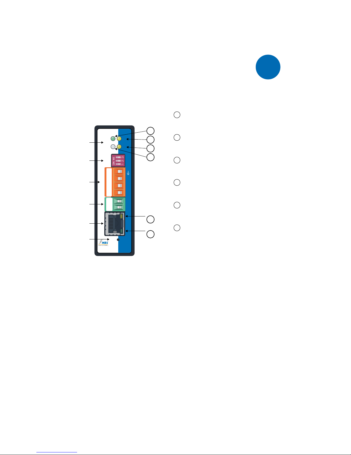
UBR-01 | Mk II front view
MS/TP
LAN
B+
–
PWR
+
A-
GND
S3
S2
S1
TX
RX
ST.
PWR.
Reset
UBR-01 | Mk II
Universal Gateway
+24
GND
B+
A-
Shld
AGND
Reset
Link/Activity
Netzwerk
Netzteil
MS/TP
DIP-Schalter
LED
6
10/100 MBit/s
5
4
3
1
2
Status LED:
Red for approx. 6 s:
Self test after switching on
Flashing green:
Normal state
Flashing alternately red and green:
during the reset process
(see chap. Reset)
1
PWR. (Power)
This green LED lights up when the power
supply is activated..
2
RX (MS/TP RxD)
This yellow LED lights up when the router
receives data from the MS/TP network.
3
TX (MS/TP TxD)
This yellow LED lights up when the router
sends data to the MS/TP network.
4
ST. (Status)
This multi-coloured LED shows the
system status of the router.
5
10/100 MBit/s
This yellow LED indicates the speed of
the connection to the network.
6
Link/Activity
This green LED indicates the status of the
network connection and activity.
LED
Indication of the system status of the router with
four LEDs
DIP switches
Activation of bus termination and network bias
resistors
MS/TP
4-pole Weidmüller socket
Power unit
2-pole connection to voltage supply
Network
RJ45 socket (LAN)
Reset
Reset button to restore factory settings
Device views
Chapter 3 Device views
11
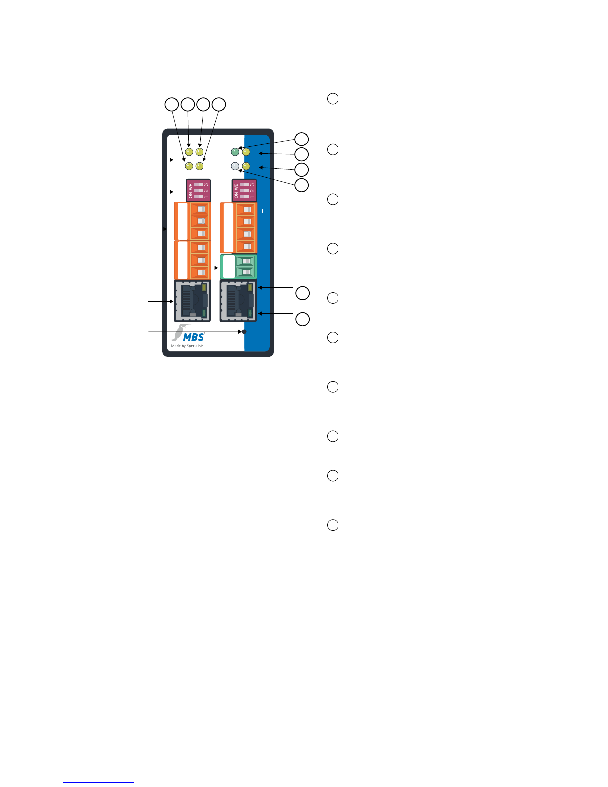
1
TX (MS/TP TxD, RS232)
This yellow LED lights up when the
router sends data to the MS/TP
network.
2
RX (MS/TP RxD, RS232)
This yellow LED lights up when the
router receives data from the MS/
TP network.
3
RX (MS/TP RxD, RS485)
This yellow LED lights up when the
router receives data from the MS/
TP network.
4
TX (MS/TP TxD, RS485)
This yellow LED lights up when the
router sends data to the MS/TP
network.
5
PWR. (Power)
This green LED lights up when the
power supply is activated.
6
RX (MS/TP RxD, RS485)
This yellow LED lights up when the
router receives data from the MS/
TP network.
7
TX (MS/TP TxD, RS485)
This yellow LED lights up when the
router sends data to the MS/TP
network.
8
ST. (Status)
This multi-coloured LED shows the
system status of the router.
9
10/100 MBit/s
This yellow LED indicates the
speed of the connection to the
network.
10
Link/Activity
This green LED indicates the status
of the network connection and
activity.
Status LED:
Red for approx. 6 s: Self test after switching on
Flashing green: Normal state
Flashing alternately red and green: during the reset process (see chap. Reset)
Reset
LAN
1
LAN
2
B+
–
PWR
+
A-
GND
S3
S2
S1
TX
RX
ST.
PWR.
UBR-02
BACnet Router
TX
RX
TX
RX
RS485
RS485
RS232
RS232 RS485
TXD
RXD
GND
B+
A-
GND
S3
S2
S1
B+
A-
Shld
AGND
+24
GND
B+
A-
GND
TXD
RXD
GND
8
7
5
6
431 2
Link/Activity
10
10/100 MBit/s
9
Netzwerk
1 + 2
Netzteil
MS/TP
DIP-
Schalter
LED
Reset
UBR-02 front view
LED
Indication of the system status of the router with
eight LEDs
DIP switches
Activation of bus termination and network bias
resistors (COM1, COM3)
MS/TP
Right: Weidmüller socket (COM1)
Left: RS485 (COM3), RS232 (COM2)
Power unit
2-pole connection to voltage supply
Network 1 + 2
2 x RJ45 sockets (LAN)
Reset
Reset button to restore factory settings
Chapter 3 Device views
12
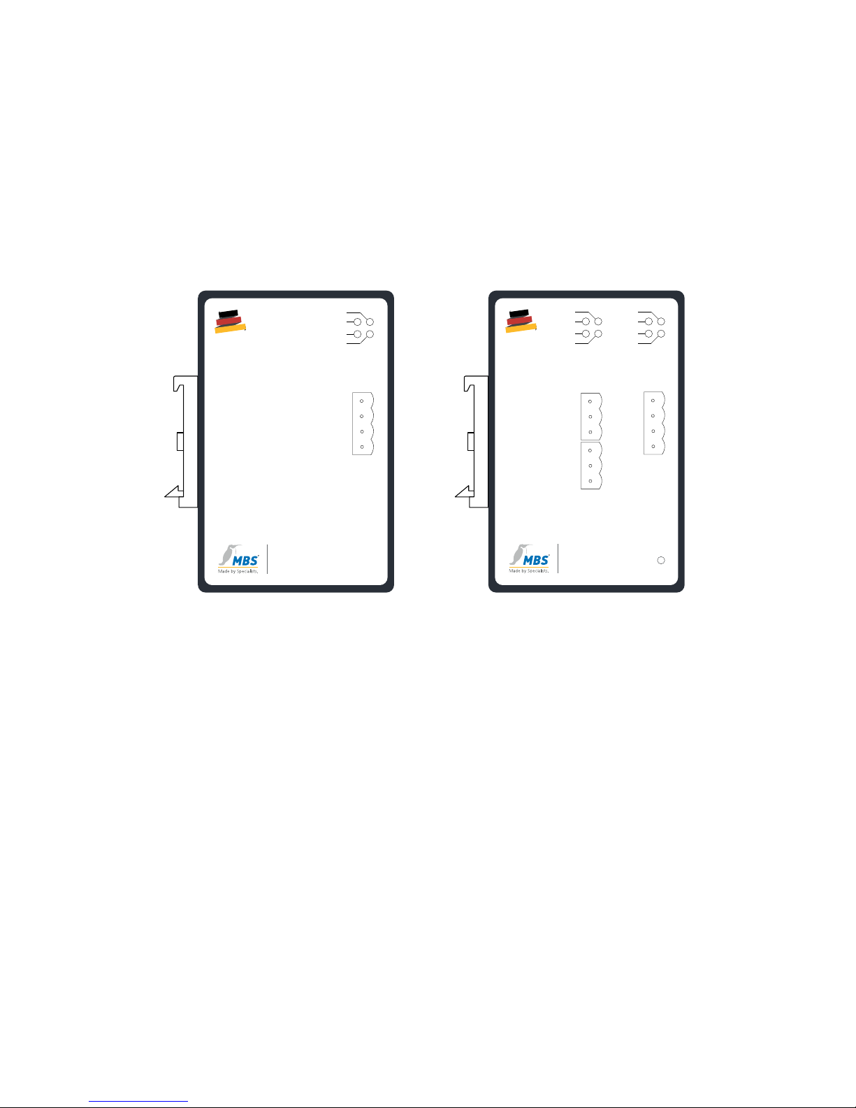
Side view
The following data and diagrams are shown on the left-hand side of the
casing of the MBS UBR and assigned to the functional elements on the front:
• Designation and diagram of the positions of the LEDs and ports
• Functions of the individual DIP switches
• Type designation of the MBS BACnet Router
MADE
IN
GERMANY
10/100 Mbit/s
12-24V DC/AC
Ethernet
Link/Act.
Power
B+
A-
GND
Shld
RX
Power
Status
TX
Reset
UBR-01 | Mk II
BACnet Router
www.mbs-solutions.de
S3 = Termination
S1 = Network Bias
S2 = Network Bias
MSTP
COM1
S3 = Termination
MSTP
COM3
RS232
COM2
LAN 2 LAN 1
10/100 Mbit/s
Ethernet
Link/Act.
S1 = Network Bias
S2 = Network Bias
B+
A-
GND
RS485 RX
RS232 RX
RS485 TX
RS232 TX
TXD
RXD
GND
Reset
S3 = Termination
10/100 Mbit/s
12-24V DC/AC
Ethernet
Link/Act.
Power
S1 = Network Bias
S2 = Network Bias
B+
A-
GND
Shld
RX
Power
Status
TX
MADE
IN
GERMANY
UBR-02
BACnet Router
www.mbs-solutions.de
UBR-01 | Mk II UBR-02
Top
On the top of the casing there is a product label with the following data:
• Type designation of the MBS BACnet Router
• Ethernet MAC address (additional MAC address on UBR-02)
• Default IP address
Rear
On the rear of the casing there is a DIN top hat rail (TS 35 as per EN 60715).

Chapter 4 Start-up and operation
13
4
Start-up and operation
To put the MBS UBR into operation and configure it, you need the following
hardware and software:
Power unit for the UBR
• Computer
• Installed web browser
• Installed PDF reader
• Network cable
The MBS UBR provides an integrated web server for configuration.
Chapter 4.2.1 describes the steps required to access the web server.
The user handbook is also available as a PDF file in the Help directory on the
web server. The handbook can be displayed and printed out as necessary
with a PDF reader.
Hardware installation
Assembly
The router has a mount at the rear for easy installation on top of hat rails
as per EN 60715. Install the router in the electrical cabinet and make sure
that there is sucient ventilation to ensure the specified temperature range
(0…45 °C).
Electrical installation
Connect the MBS UBR to the green, two-pole port with a power supply as
per the technical specifications. An international power supply is optionally
available if required.

Chapter 4 Start-up and operation
14
Ethernet network installation
Connect the Ethernet network cable (RJ-45 port) to the MBS UBR. Use CAT5
UTP or STP cables (or equivalent). Avoid laying cables parallel to power lines,
e.g. to motors, frequency converters etc.
MS/TP network installation
Connect the MS/TP or RS485 network to the MS/TP port (orange). Adhere
to the instructions for connecting MS/TP or RS485 networks as per ASHRAE
135-2016 chapter 9.2 (BACnet standard). Use the DIP switches to activate the
network bias and the terminating resistor.
Configuring the router using the web interface
Opening the web interface
The router has an integrated web server for configuration. You use the web
interface to configure the IP, BACnet and other settings, and you save the
changes with [Save]. Following changes to the network configuration it is
sometimes necessary to restart the router.
With the factory settings the web server is accessible at the following IP
address:
• IP address: 169.254.0.1
• Network mask: 255.255.0.0
Connect the MBS UBR to your PC with the network cable for configuration.
Enter the IP address of the UBR web server in a web browser:
http:// 169.254.0.1.
Note:
Note that your computer's LAN connection has to be set appropriately.
Have the IP address, for example, set automatically with the DHCP
server activated. For a manual setting define the IP address as
169.254.0.2, for example. The network mask remains at 255.255.0.0.
Chapter 4 Start-up and operation
15
Attention:
The guarantee will become null and void if the MBS UBR is connected
to an unsuitable power supply or the casing is opened. There are no
controls inside the casing. Do not establish a connection with the
BACnet network before the MBS UBR has been fully configured.
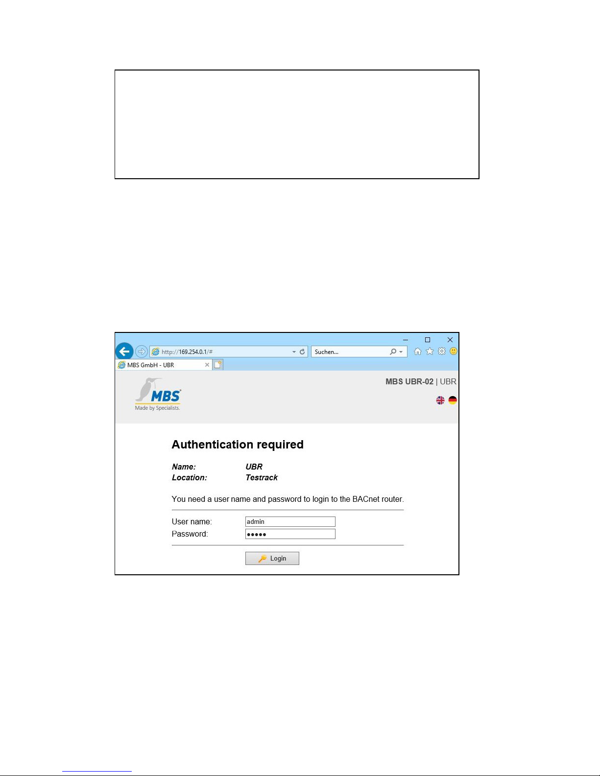
Logging on to the web server
Enter the following user name and password (preconfigured administrator
access) to sign in to the web server:
• Username: admin
• Password: admin
You can change the access data using the configuration pages.
Chapter 4 Start-up and operation
16
Web server language
The router provides the website in both German and English. You switch the
language in the web interface using the respective flag symbols at the top
right.
The web interface contains the following menu areas for configuration of the
router:
• GENERAL
• BACNET
• DIAGNOSIS
• HELP
Each menu area includes submenus in the left-hand column which you use to
call up the individual configuration pages/views.
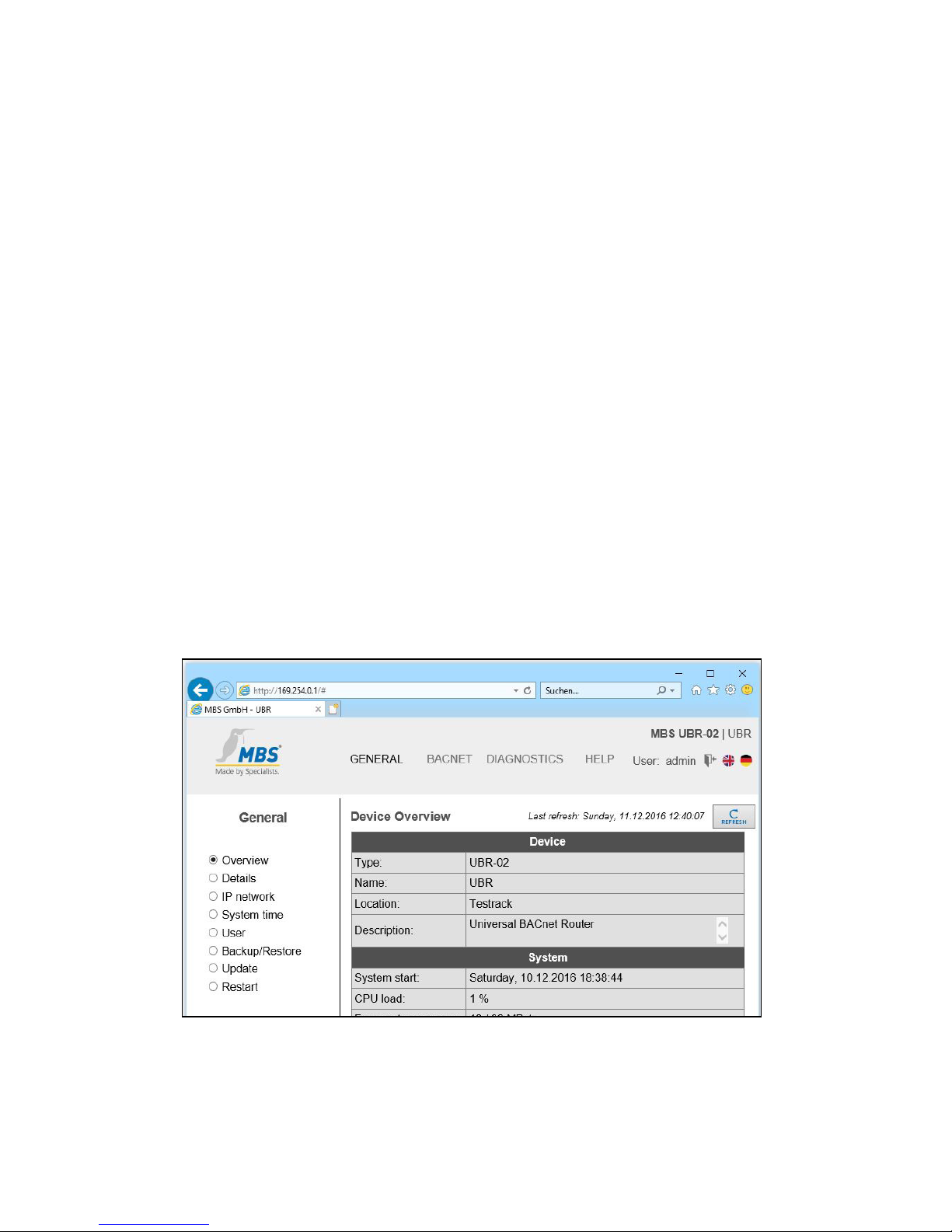
"General" area
General > overview
After logging in, the router loads an overview page for the device.
You can use [Refresh] to refresh the displayed information.
Chapter 4 Start-up and operation
17
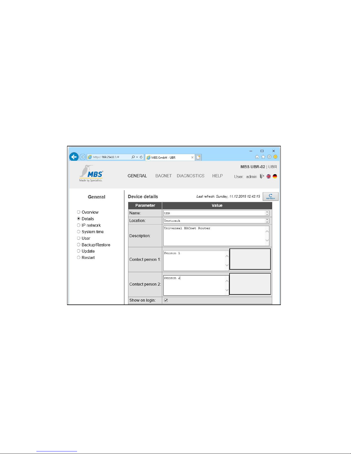
General > information
Information on the device name, the installation location, a description and
contact details can be stored in the router. This information is used in order
to identify the respective router better in the network. Edit the input fields for
this purpose.
An image can be stored for each contact as required (e.g. photo, company
logo etc.). To add a new image or replace an existing image, click on the
placeholder with the bold border or on the existing image. The company
logo dialogue opens. This is where you select the desired image or delete an
existing image.
Chapter 4 Start-up and operation
18
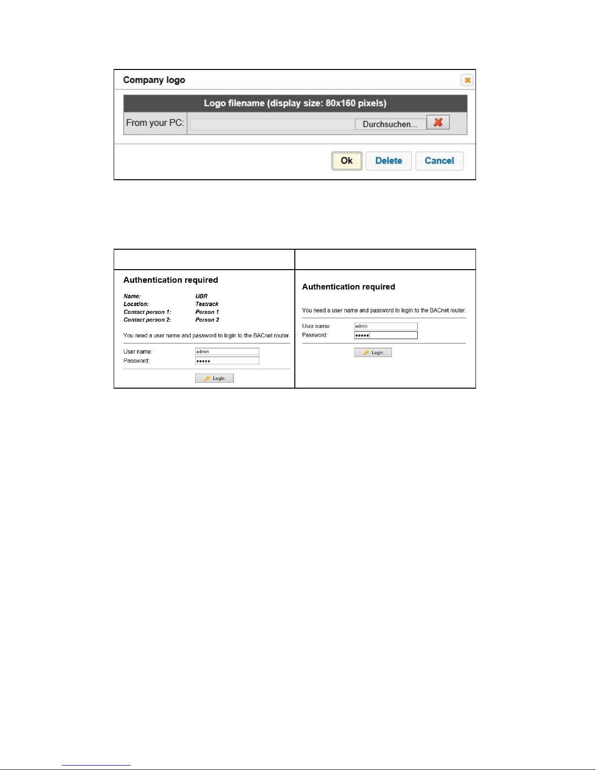
If the checkbox [Show on login] is activated, the information which has been
entered here is displayed on the router's login page and on the configuration
page General > Overview.
Checkbox selected Checkbox not selected
Important:
To save the settings on the configuration pages, click on [Save].
An info dialogue then confirms the application of the entries.
General > IP network
Configure the IP network settings on this configuration page.
 Loading...