

MBS Mortise Lock Service Manual


Index
MBS Service Manual
Moritse Lock General Dimentsion
Deadbolt Lock General Dimentsion
Specifications
Functions
Trim Parts
Lever Assemblies
Lever & Roses
Cylinders & Strikes
pg 3
pg 4
pg 7-10
pg 11-39
pg 40-44
pg 45
pg 46
pg 47
Faceplates
pg 48
pg2
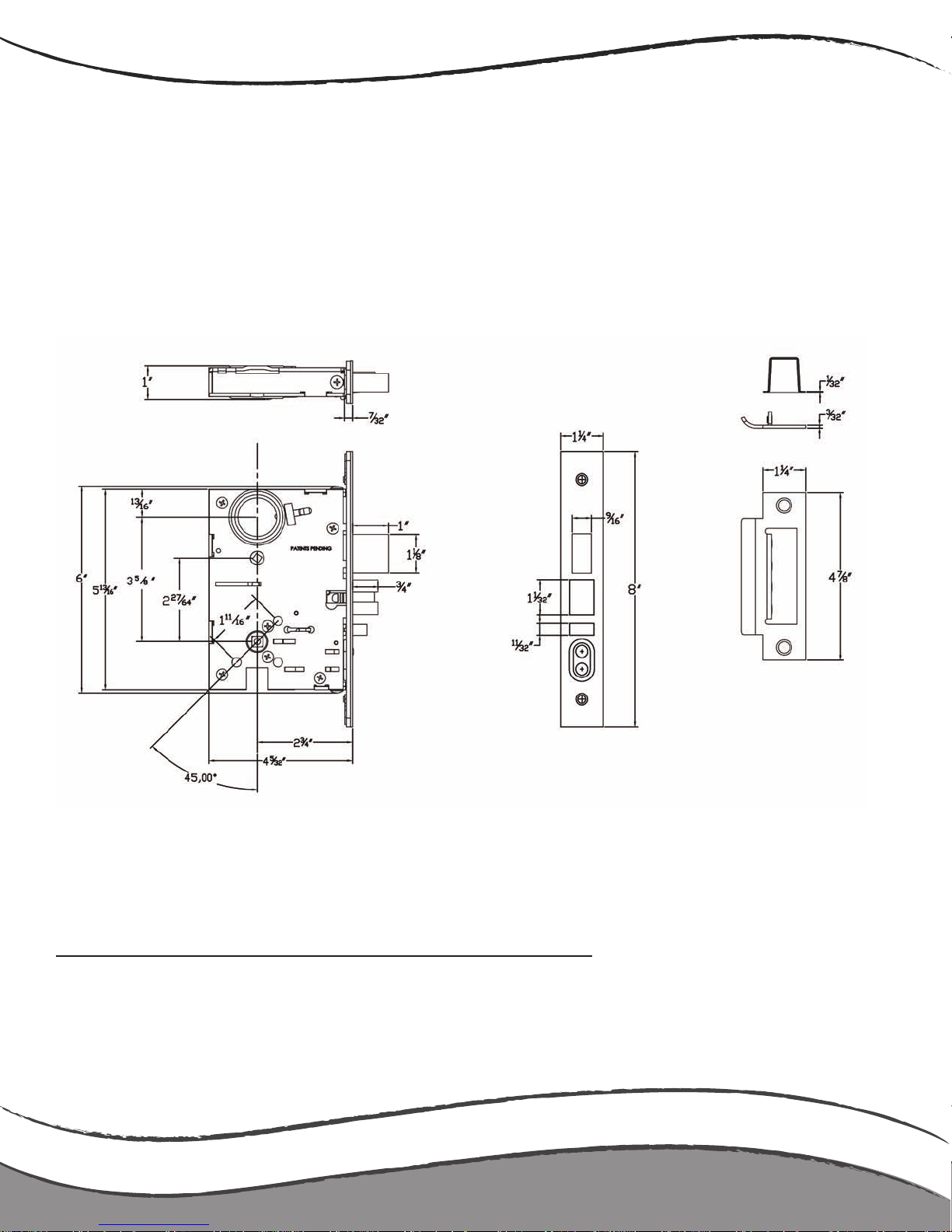
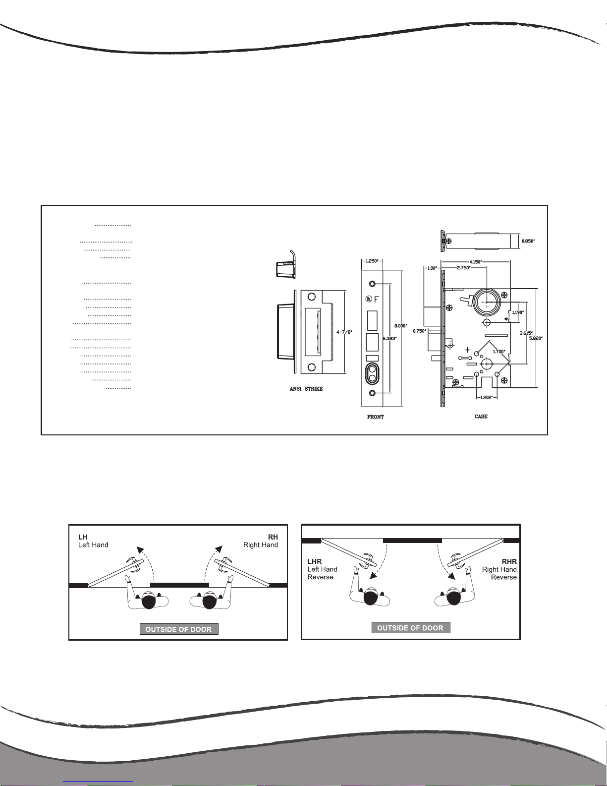
Lock Dimensions
Mortise Lock Dimensions
HANDABLE LOCK LH VERSION SHOWN
Feature Dimensions
Case size 5 7/8” x 4 1/4” x 1”
Backset: 2 3/4”
Door thickness range: 1 3/4” standard-up to 5”
pg3
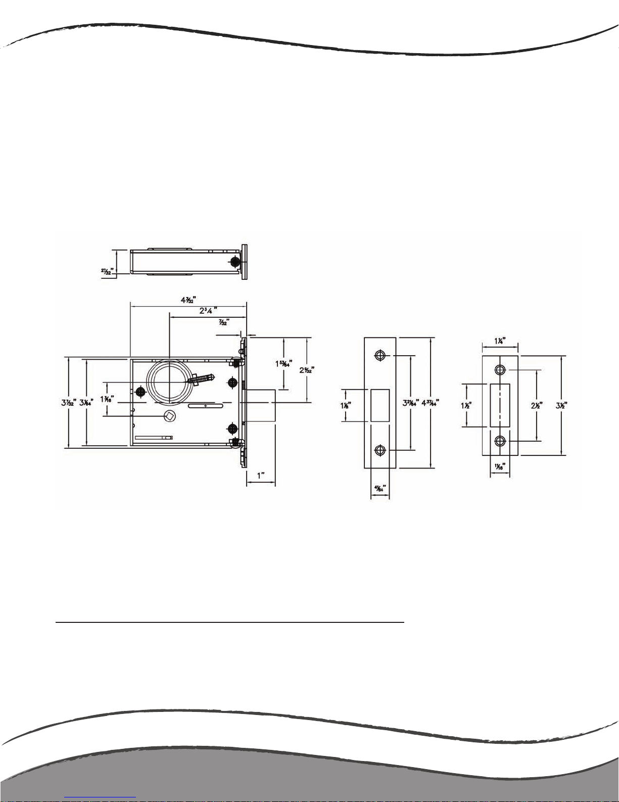
Deadbolt Lock Dimensions
HANDABLE LOCK LH VERSION SHOWN
Lock Dimensions
Feature Dimensions
Case size 4 3/16” x 3 5/8” x 1”
Backset: 2 3/4”
Door thickness range: 1 3/4” standard-up to 5”
pg4
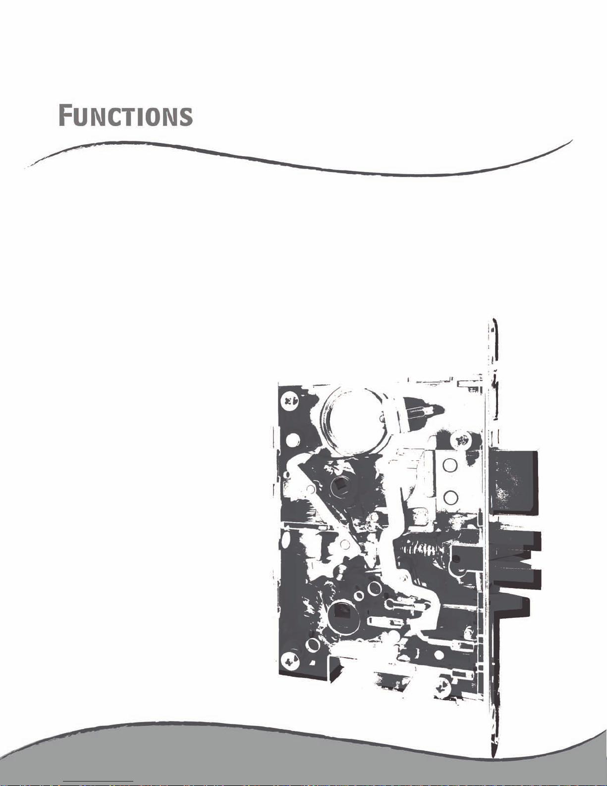

Functions
MBS Service Manual
Moritse Specification
Moritse Functions List
Moritse Functions List ANSI No.
MBS A78801
MBS A78802
MBS A78804
MBS A78805
MBS A78806
MBS A78807
MBS A78808
MBS A78809
MBS A788011
MBS A788013
MBS A788014
MBS A788015
MBS A788016
MBS A788019
MBS A788020
MBS A788021
MBS A788022
MBS A788029
MBS A788030
MBS A788031
MBS A788032
MBS A788033
MBS A788035
F01
F02
F04
F05
F06
F07
F08
F09
F11/F12
F13
F14
F15
F16/F17/F18
F19
F20
F21
F22
F29
F30
F31
F32
F33/F34
F35
pg7-10
pg11-37
pages
pg 15
pg 16
pg 17
pg 18
pg 19
pg 20
pg 21
pg 22
pg 23
pg 24
pg 25
pg 26
pg 27
pg 28
pg 29
pg 30
pg 31
pg 32
pg 33
pg 34
pg 35
pg 36
pg 37
Moritse Deadbolt Functions List ANSI No. pages
MBS A5300
MBS A5300NYC
pg 38
pg 39
pg6
MBS Service Manual
1 ¾” standard, other thicknesses available
when specied
2 ¾”
Heavy gauge plated steel
Wrought stainless steel or brass- adjustable
angle and attached by screws to the lock
case front
1” throw, stainless steel with hardened
anti-saw pins
Stainless steel latch
Stainless steel
Push buttons- chrome plated brass
Stainless steel or brass, 4 7/8” X 1 ¼”
curved lip ANSI strike
Handed, reversible in eld
As specied
As specied
As specied
As specied
UL listed, 3 hour re doors, single and pairs
Meets all Grade 1 security, operational,
dimensional and cycling requirements
of ANSI/BHMA A156.13 Series 1000,
Lock body conforms to Federal Standard
FF-H-106 Type 86/87
Door thickness
Backset
Lock case
Armored Front
Dead bolt
Latch bolt
Guard bolt
Stop works
Strike
Handing
Trim
Cylinder
Keyway
Finishes
UL Listings
ANSI Specication
Specifications
FEATURES & SPECIFICATIONS
HANDING
pg7
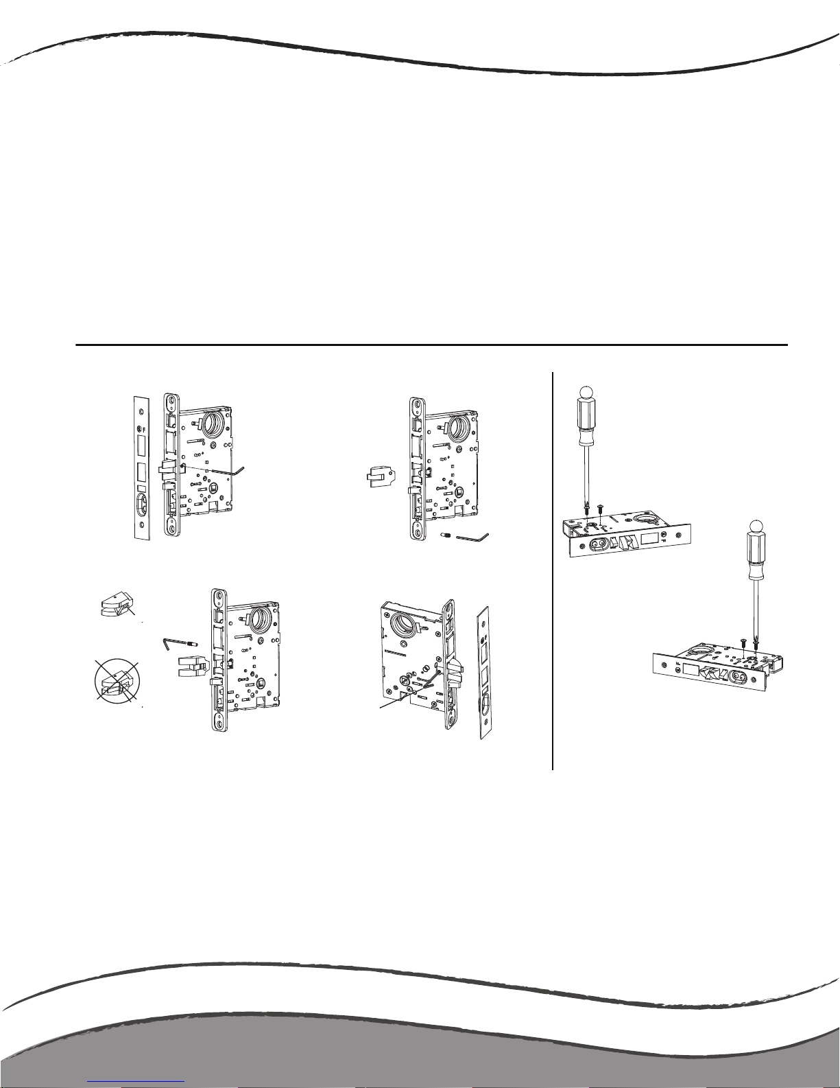
Handing Change Instruction
Mortise handing change instruction
Change the latchbolt position
1. Remove special screw with
provided allen wrench
3. Rotate Latch bolt 180˚ and
reinstall into lock, pushing the latch
bolt into the lock and then releasing.
MAKE SURE FOOT IS
UNDER LATCH SURFACE
CANNOT PUT IN LOCK
WITH FOOT ABOVE
LATCH SURFACE
2. Pull latch bolt out of lock
4. Reinstall the special screw
and tighten securely with
the provided allen wrench.
FROM OPPOSITE SIDE
INSERT SPECIAL SCREW
AND TIGHTEN WITH
ALLEN WRENCH
Change the locking slide position
1. Remove 2 screws as shown above
2. Turn lock over to opposite side
and reinstall screws as shown above.
To ensure locking slide does not bind,
manually push to the desired side or
alternate tightening each screw every
2-3 turns.
MBS Service Manual
pg8
Lock Parts and Functions
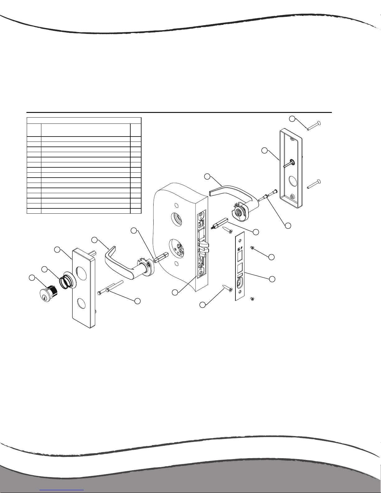
Regular / Wide Escutcheon
PARTS LIST DESCRIPTION
ITEM#
DESCRIPTION
QTY
1
Cylinder (optional) #4046-C-FW-OB/KD
1
2
Cylinder spring/collar (optional) #MX S8235+MX S8233
1
3
Escutcheon O/S #MX E8012-OC
1
4
Lever assembly (O/S left) #Various
1
5 Spindle #TS 8601 1
6
Lever assembly (I/S left) #Various
1
7
Escutcheon I/S #MXE8012-IP-FIN
1
8 Escutcheon mounting screws #MX E9019-FIN 2
9 Assembly mounting screw #MX S8015 2
10 Spindle #TS 8602 1
11 Face plate screw #MX 30430 2
12 Face plate #MBS 88820 1
13 Mortise lock case mounting screw #MX 30410 2
14 Mortise lock case #TS A6820 1
15 Mounting post # MX S8016 2
NOTE: LEFT HAND mounting is shown
Step 1 Prepare door per supplied template
Step 2 Insert mortise lock case (item 14) into mortise cutout and fasten to
door with screws (item 13)
Step 3 Insert inside and outside spindles (items 5 & 10) into the mortise lock
case hub and tighten screw
Step 4 Insert 2 mounting posts (item 15) into the outside lever assembly
(item 4)
Step 5 Position outside (O/S) lever assembly onto the mortise lock case- line
up spindle & mounting posts with mortise lock case
Step 6 Position inside (I/S) lever assembly (item 6) onto the mortise lock
case- line up spindle
Step 7 Using the 2 mounting screws (item 9) fasten the I/S lever assembly
to the O/S lever assembly
Step 8 Install O/S & I/S Escutcheons (items 3 & 7) over lever assemblies
and fasten with screws (item 8)
Step 9 Optional- Screw in cylinder (item 1) using spring & cylinder collar
(item 2)- some models use no cyl. collar
Step 10 Thread cylinder to operational depth and secure with mortise lock case
set screw
Step 11 Fasten face plate (item 12) on using screws (item 11)
Step 12 ALWAYS CHECK OPERATION OF LOCK SET PRIOR TO LOCKING/SHUTTING
DOOR
TO CHANGE HANDING: REVERSE INSIDE & OUTSIDE LEVER ASSEMBLIES (items 4 &
6) & CHANGE MORTISE LOCK CASE HANDING
2
1
3
4
6
8
7
12
11
13
14
15
10
5
9
Non-Handed Mortise Lockset Installation Guide
pg9
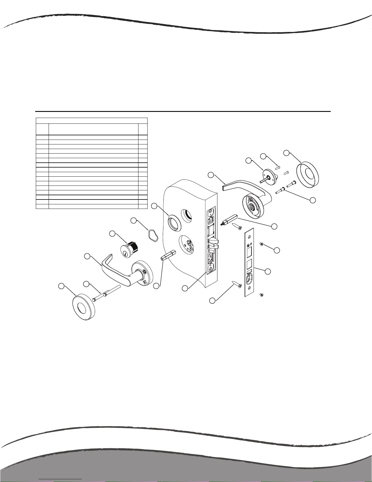
Non-Handed Mortise Lockset Installation Guide
NOTE: LEFT HAND mounting is shown
Step 1 Prepare door per supplied template
Step 2 Insert mor tise lock case (item 15) into mortise cutout and
fasten to door with screws (item 14)
Step 3 Insert inside and outside spindles (items 11 & 16) into the
mortise lock case hub and tighten screw
Step 4 Insert 2 mounting posts (item 2) into the outside lever
assembly (item 3)
Step 5 Press rose (item 1) onto the outside lever assembly (item 3)
Step 6 Position outside (O/S) lever assembly onto the mortise lock
case-line up spindle & mounting posts with mortise lock case
Step 7 Position inside (I/S) lever assembly (item 7) onto the mortise
lock case- line up spindle
Step 8 Using the 2 mounting screws (item 10) fasten the I/S lever
assembly to the O/S lever assembly
Step 9 Press rose (item 1) onto the inside lever assembly (item 7)
Step 10 Optional- Screw in cylinder (item 4) using spring and collar
(items 5 & 6)
Step 11 Thread cylinder to operational depth and secure with mortise
lock case set screw
Step 12 Fasten face plate (item 13) on using screws (item 12)
Step 13 Install thumb turn (items 8 & 9) if required
Step 14 ALWAYS CHECK OPERATION OF LOCK SET PRIOR TO LOCKING/
SHUTTING DOOR
TO CHANGE HANDING: REVERSE INSIDE & OUTSIDE LEVER ASSEMBLIES
(items 3 & 7) & CHANGE MORTISE LOCK CASE HANDING
PARTS LIST DESCRIPTION
ITEM#
DESCRIPTION
QTY
1
Rose (Inside & Outside) #MX S8012-FIN
2
2 Mounting post #MX S8016 2
3
Lever assembly (O/S left) #Various
1
4
Cylinder (optional) #4046-C-FIN-OB/KD
1
5
Cylinder spring (optional) #CON 25905-C
1
6
Cylinder collar (optional) #MX S8233
1
7
Lever assembly (I/S left) #Various
1
8
Thumb turn (optional) #DRT AS 99319-FIN
1
9
Thumb turn mounting screws (optional) #DRT S99833-H
2
10 Assembly mounting screws #MX S8015 2
11 Spindle #TS8602 1
12 Face plate screw #MX 30430 2
13 Face plate #MBS 88820 1
14 Mortise lock case mounting screw #MX 30410 2
15 Mortise lock case #TS A6820 1
16 Spindle #TS 8601 1
2
1
3
4
5
6
16
7
8
9
1
14
13
12
11
10
15
Sectional
Lock Parts and Functions
pg10
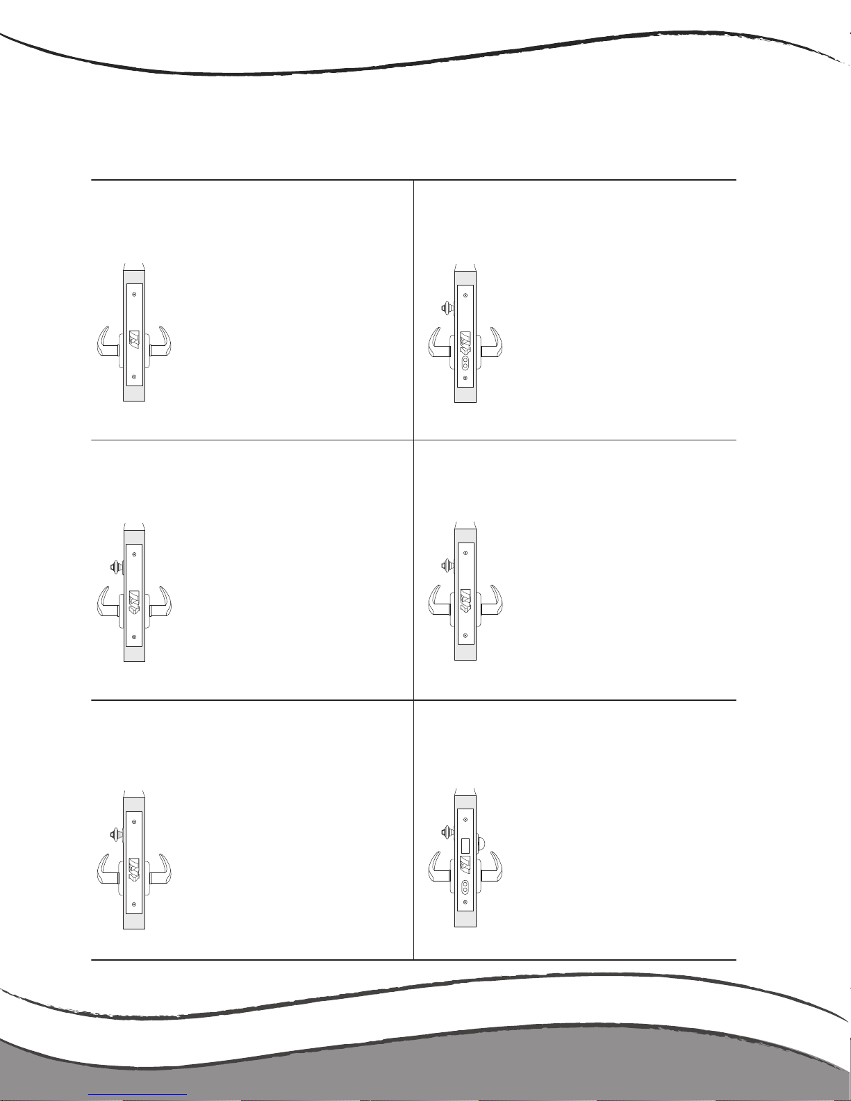
Functions
Latch bolt operated by lever from either
side, except when outside lever is made
inoperative by a stop or mechanical means
other than key. When outside lever is
locked, latch bolt is retracted by key from
outside or by operating inside lever.
***Auxiliary dead bolt latch.
ANSI F04 - Entry/Office (MBS A78804)
Latch bolt operated by lever from either
side, except when outside lever is locked
from outside by key. When outside lever
is locked, latch bolt may be retracted by
key, or by operating key and outside lever
from outside or by operating inside lever.
***Auxiliary dead bolt latch.
ANSI F05 - Classroom (MBS A78801)
Latch bolt operated by lever either side,
except when outside lever is locked from
outside by key. Latch bolt can be locked
in a retracted position by key. When
outside lever is locked, latch bolt is
retracted by key from outside or by
operating inside lever unless latch bolt
has been locked in a retracted position.
***Auxiliary dead bolt latch.
ANSI F06 - Holdback (MBS A78806)
Latch bolt operated by key from outside
or by rotating inside lever. Outside lever
is always inoperative.
***Auxiliary dead bolt latch.
ANSI F07 - Storeroom or Closet (MBS A78807)
Latch bolt operated by lever from either
side, except when outside lever is made
inoperative by a stop or mechanical
means other than key. Dead bolt is
operated by turn inside. Key outside
operates both bolts.
ANSI F08 - Front Door or Corridor Lock
(MBS A78808)
Latch bolt operated by lever from either
side at all times.
ANSI F01 - Passage or Closet (MBS A78801)
Functions
pg11
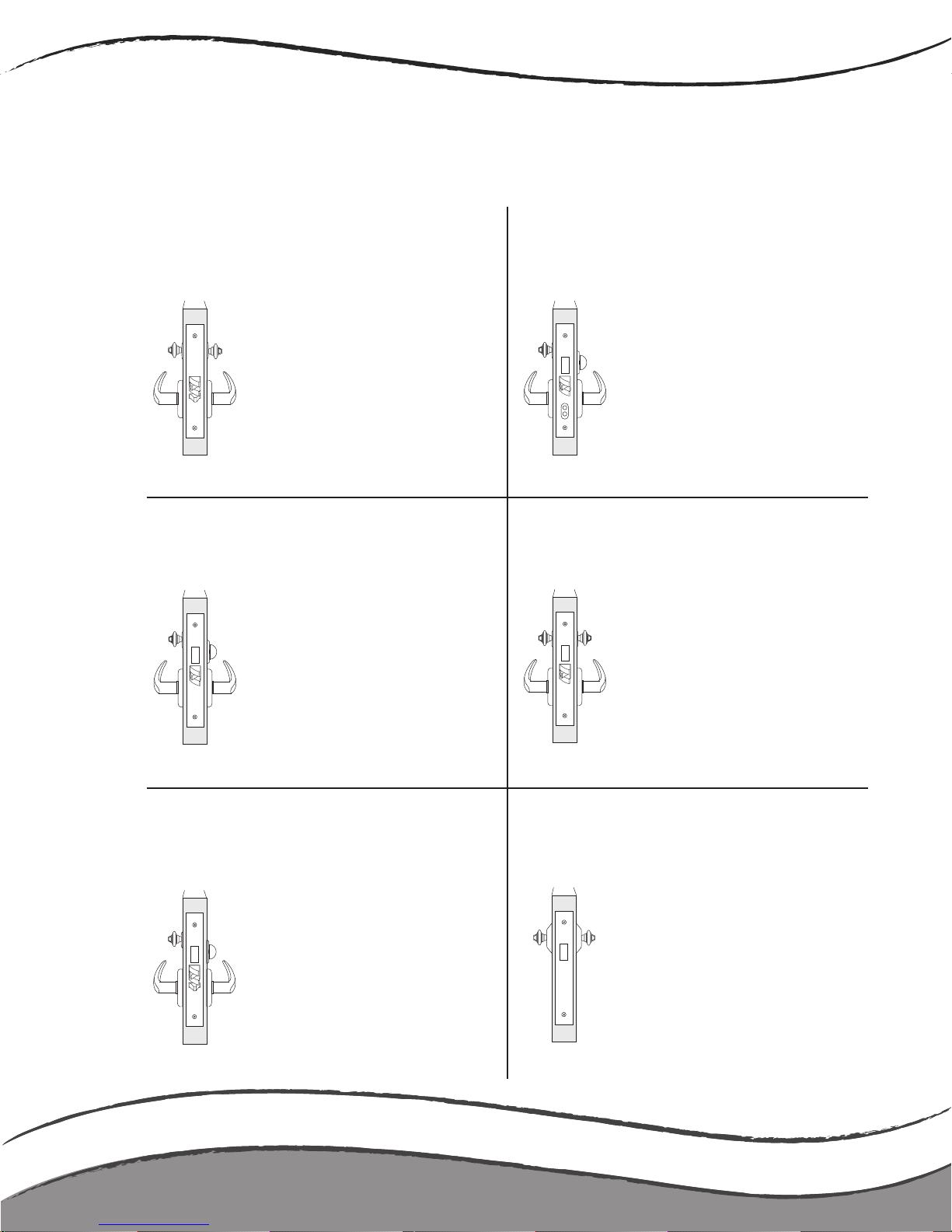
Functions
Latch bolt operated by lever from either
side, except when outside lever is locked
by key from inside. When outside lever is
locked, latch bolt is retracted by key from
outside or by operating inside lever.
***Auxiliary dead bolt latch
ANSI F09 - Apartment / Exit or Public Toilet
(MBS A78809)
Latch bolt operated by lever from either
side. Dead bolt operated by key from
either side.
ANSI F14 - Storeroom (MBS A78814)
Dead bolt operated by key on either side.
ANSI F16 - Deadlock (MBS A78816)
Latch bolt operated by key from outside
or by rotating inside lever. Outside lever
is always inoperative. Dead bolt operated
by thumb turn from inside and all keys
except emergency and display key are
shut out. Operating inside lever retracts
both bolts. ***Auxiliary dead bolt latch.
ANSI F15 - Hotel or Motel (MBS A78815)
Latch bolt operated by lever from either
side. Dead bolt projected by key from
outside and thumb turn from inside.
Operating inside lever retracts both bolts
and unlocks outside.
ANSI F13 - Dormitory or Exit (MBS A78813)
Latch bolt operated by lever from either
side, except when outside lever is made
inoperative by a stop or mechanical means
other than key. Dead bolt projected by key
from outside and by turn from inside.
Deadbolt retracted by key from outside and
by turn from inside. Operating inside lever
retracts both bolts and outside remains
locked.
ANSI F11 & F12 - Dormitory or Exit
(MBS A78811)
Functions
pg12
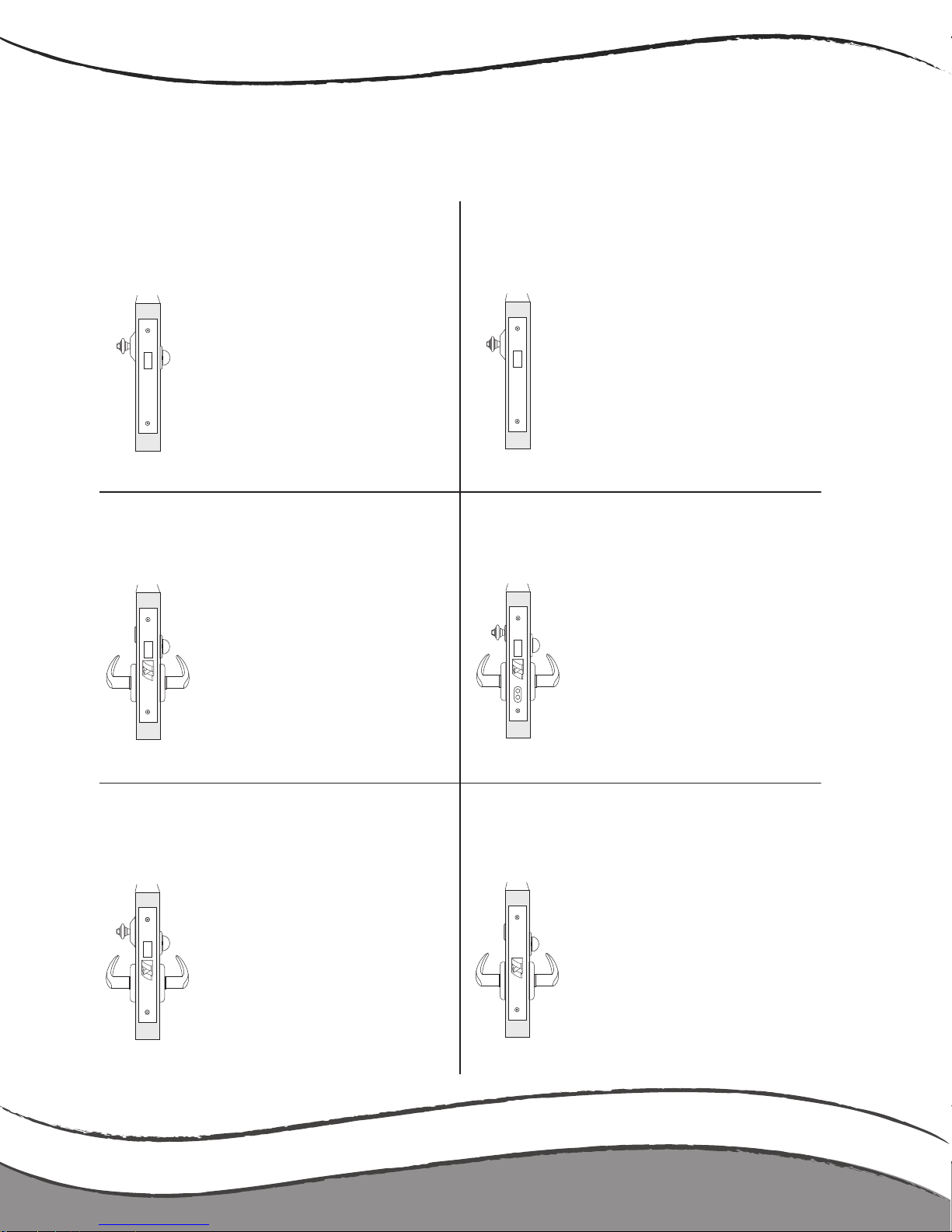
Functions
Dead bolt operated by key outside and
turn piece inside.
ANSI F17 - Deadlock (MBS A78816)
Dead bolt by key from outside only.
ANSI F18 - Deadlock (MBS A78816)
Latch bolt operated by lever from either
side, except when outside lever is locked
by inside turn. Operating inside lever,
closing door or operating outside
emergency release unlocks outside lever.
ANSI F22 - Privacy (MBS A78822)
Latch bolt operated by lever either side.
Dead bolt operated by key outside or
by turn from inside.
ANSI F21 - Dormitory with Dead bolt
(MBS A78821)
Latch bolt operated by lever from either
side, except when outside lever is made
inoperative by push button rocker. Dead
bolt projected by key from outside and
by thumb turn from inside. Key outside
operates both bolts. Operating inside
lever retracts both bolts and outside
remains locked. Latch bolt is deadlocked
whenoutside lever is made inoperative or
when the dead bolt is projected. When
dead bolt is retracted, lever is unlocked by
stop or mechanical means other than key.
ANSI F20 - Entrance/Apartment/Dormitory
(MBS A78820)
Latch bolt operated by lever from either
side. Dead bolt operated by turn from
inside and emergency release from outside.
Operating inside lever retracts both bolts.
ANSI F19 - Privacy or Bathroom (MBS A78819)
Functions
pg13
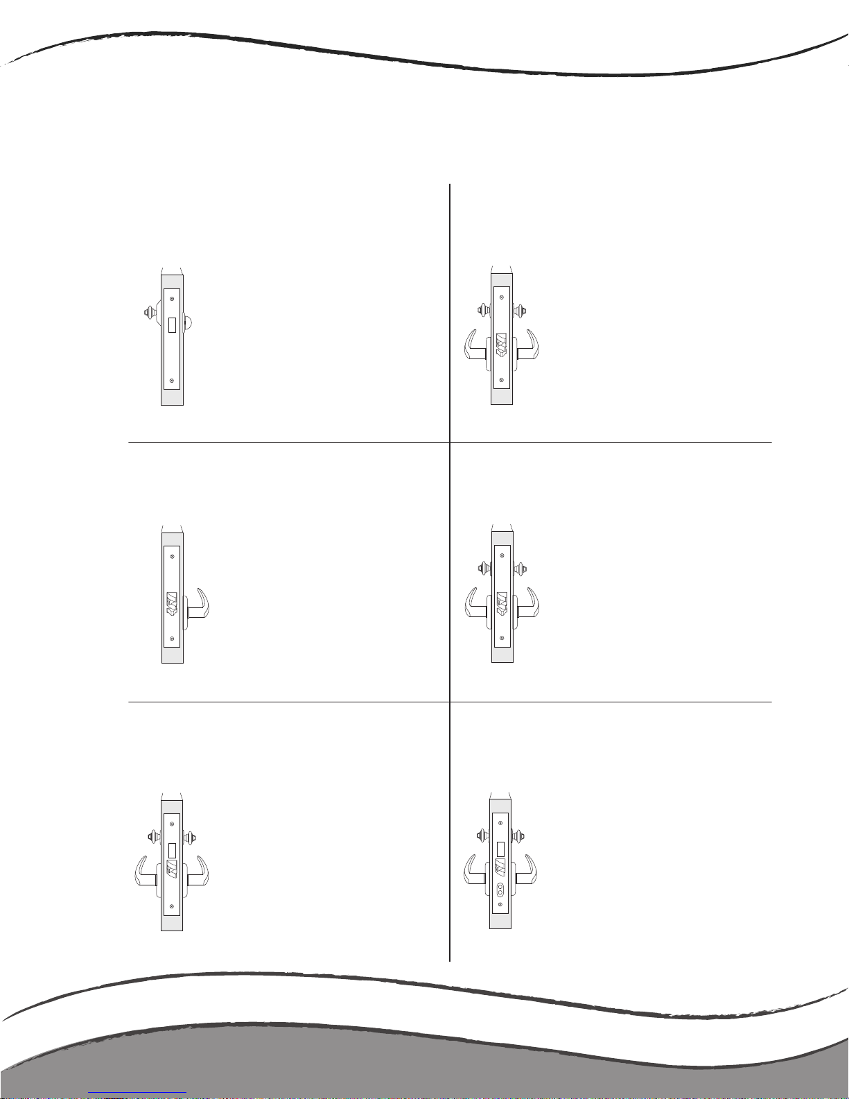
Functions
Latch bolt operated by lever from inside.
Non removable blank lever or no lever
outside. ***Auxiliary dead bolt latch.
ANSI F31 - Exit (MBS A78831)
Latch bolt operated by key either side.
Both levers always inoperative.
***Auxiliary dead bolt latch.
ANSI F30 - Institutional (MBS A78830)
Key from outside operates dead bolt.
Turn from inside retracts but does not
project dead bolt.
ANSI F29 - Classroom Dead bolt (MBS A78829)
Latch bolt operated by lever from either
side, except when outside lever is made
inoperative by a stop or mechanical
means other than key. Dead bolt operated
by key from either side.
ANSI F35 - Storeroom with Dead bolt
(MBS A78835)
Latch bolt operated by lever either side,
except when outside lever is locked from
inside or outside by key. Dead bolt
operated by key either side. Inside
lever retracts both bolts and unlocks
outside lever.
ANSI F33 & F34 - Intruder Dead bolt
(MBS A78833)
Latch bolt operated by lever either side,
except when outside lever is locked from
inside or outside by key. When outside
lever is locked, latch bolt is retracted by
key from inside or outside or by operating
inside lever. ***Auxiliary dead bolt latch
ANSI F32 - Intruder Latch bolt (MBS A78832)
Functions
pg14
 Loading...