

Page 1
Sheeter
Translation of the original operating manual
Keep for future reference!
SVC525C
Page 2

Type of machine:
Sheeter
Configuration:
Type of document:
Version:
Status as
V1.1
11/04/2014
of:
Language:
English
Manufacturer:
Subject to alterations!
SVC 525C
Translation of the original operating manual
Author:
Wolfgang Matzner
Machine no.:
File name:
MBO Maschinenbau Oppenweiler Binder GmbH & Co. KG
PO Box 1 169
71567 Oppenweiler
GERMANY
Tel.: +49 7191 46 0
Fax: +49 7191 46 34
http://www.mbo-folder.com
info@mbo-folder.com
BA_SVC525C
_V1.1_us-en
Copyright: This documentation is subject to copyright law. The claimed copyright includes
all forms and types of copyright-protected materials and information that are
currently permitted. No part of the documentation may be copied, otherwise
duplicated, edited or translated into other languages, regard less of the manner
in which or with which tools this takes place.
Electronically-stored information provided by the manufacturer (CD-ROM, Internet) may be printed out by the user if the created print medium serves the
purpose of use or service of the product described.
Page 3

Name plate and
1
2
3
5
4
CE marking:
For all questions relating to your machine, please contact your
MBO agency.
You can find the address on our home page: www.mbo-folder.com.
For the identification of the machine and the most important machine data,
see the name plate on the machine.
1 CE marking
2 Type of machine
3 Commission number
Illustration 1: Name plate
4 Year of manufacture
5 Name plate
Always specify these details for inquiries, service and spare parts orders:
• Commission number
• Type of machine
Sheeter SVC 525C
Page 4

EC Declaration of Conformity
according to EC Machine Directive 2006/42/EC, Annex II, No. 1 A.
The manufacturer
MBO Maschinenbau Oppenweiler Binder GmbH & Co. KG
Grabenstraße 4-6
71570 Oppenweiler
GERMANY
hereby declares that the machine described below
Designation Sheeter
Type SVC 525C
Commissioning no.
complies with the provisions of the following EC directives
Machinery Directive 2006/42/EC
Low Voltage Directive 2006/95/EC
Harmonized standards applied:
EN ISO 12100:2010
EN 1010-1:2004+A1:2010
EN 1010-4:2004+A1:2009
EN ISO 60204-1:2006
Authorized representative for compiling the technical file:
Name Wolfgang Matzner
Address Grabenstraße 4-6
71570 Oppenweiler
GERMANY
Oppenweiler, 11/4/2014
_________________________________
Frank Eckert - Managing Director
Sheeter SVC 525C
Page 5

Table of contents
Table of contents
1 About this manual
1.1 Additional documents . . . . . . . . . . . . . . . . . . . . . . . . . . . . . . . . . . . . . . . . . . . . . . . . 8
1.1.1 Supplier documentation . . . . . . . . . . . . . . . . . . . . . . . . . . . . . . . . . . . . . . . . . . . . . . . . 8
1.2 Structure of the operating manual . . . . . . . . . . . . . . . . . . . . . . . . . . . . . . . . . . . . . . 8
1.3 Signs and symbols used . . . . . . . . . . . . . . . . . . . . . . . . . . . . . . . . . . . . . . . . . . . . 10
1.4 Description of safety messages . . . . . . . . . . . . . . . . . . . . . . . . . . . . . . . . . . . . . . . .11
1.4.1 Signal words. . . . . . . . . . . . . . . . . . . . . . . . . . . . . . . . . . . . . . . . . . . . . . . . . . . . . . . . 11
1.4.2 Structure of safety messages. . . . . . . . . . . . . . . . . . . . . . . . . . . . . . . . . . . . . . . . . . . 11
1.4.3 Safety sign . . . . . . . . . . . . . . . . . . . . . . . . . . . . . . . . . . . . . . . . . . . . . . . . . . . . . . . . . 12
1.4.4 Marking of danger spots. . . . . . . . . . . . . . . . . . . . . . . . . . . . . . . . . . . . . . . . . . . . . . . 16
1.5 User assessment of the operating manual . . . . . . . . . . . . . . . . . . . . . . . . . . . . . . 16
2 Basic safety instructions
2.1 Intended use . . . . . . . . . . . . . . . . . . . . . . . . . . . . . . . . . . . . . . . . . . . . . . . . . . . . . . 17
2.2 Reasonable foreseeable misuse . . . . . . . . . . . . . . . . . . . . . . . . . . . . . . . . . . . . . . 18
2.3 Obligation and liability . . . . . . . . . . . . . . . . . . . . . . . . . . . . . . . . . . . . . . . . . . . . . . 19
2.4 Warranty . . . . . . . . . . . . . . . . . . . . . . . . . . . . . . . . . . . . . . . . . . . . . . . . . . . . . . . . . . 20
2.5 Residual risks . . . . . . . . . . . . . . . . . . . . . . . . . . . . . . . . . . . . . . . . . . . . . . . . . . . . . 21
2.5.1 Transport, interim storage . . . . . . . . . . . . . . . . . . . . . . . . . . . . . . . . . . . . . . . . . . . . . 21
2.5.2 Set-up, commissioning. . . . . . . . . . . . . . . . . . . . . . . . . . . . . . . . . . . . . . . . . . . . . . . . 21
2.5.3 Adjustment and operation . . . . . . . . . . . . . . . . . . . . . . . . . . . . . . . . . . . . . . . . . . . . . 22
2.5.4 Maintenance. . . . . . . . . . . . . . . . . . . . . . . . . . . . . . . . . . . . . . . . . . . . . . . . . . . . . . . . 22
2.5.5 Decommissioning, storage. . . . . . . . . . . . . . . . . . . . . . . . . . . . . . . . . . . . . . . . . . . . . 23
2.5.6 Disposal . . . . . . . . . . . . . . . . . . . . . . . . . . . . . . . . . . . . . . . . . . . . . . . . . . . . . . . . . . . 23
2.6 Product-specific hazards . . . . . . . . . . . . . . . . . . . . . . . . . . . . . . . . . . . . . . . . . . . . 23
2.6.1 Entanglement hazard and crushing hazard . . . . . . . . . . . . . . . . . . . . . . . . . . . . . . . . 23
2.6.2 Cutting hazard . . . . . . . . . . . . . . . . . . . . . . . . . . . . . . . . . . . . . . . . . . . . . . . . . . . . . . 23
2.6.3 Noise . . . . . . . . . . . . . . . . . . . . . . . . . . . . . . . . . . . . . . . . . . . . . . . . . . . . . . . . . . . . . 24
2.7 Life time . . . . . . . . . . . . . . . . . . . . . . . . . . . . . . . . . . . . . . . . . . . . . . . . . . . . . . . . . . 24
2.7.1 Life time of the machine . . . . . . . . . . . . . . . . . . . . . . . . . . . . . . . . . . . . . . . . . . . . . . . 24
2.7.2 Life time of the control-technical safety components . . . . . . . . . . . . . . . . . . . . . . . . . 24
2.8 General safety instructions . . . . . . . . . . . . . . . . . . . . . . . . . . . . . . . . . . . . . . . . . . 25
2.8.1 Transport, interim storage . . . . . . . . . . . . . . . . . . . . . . . . . . . . . . . . . . . . . . . . . . . . . 25
2.8.2 Set-up, commissioning. . . . . . . . . . . . . . . . . . . . . . . . . . . . . . . . . . . . . . . . . . . . . . . . 25
2.8.3 Normal operation . . . . . . . . . . . . . . . . . . . . . . . . . . . . . . . . . . . . . . . . . . . . . . . . . . . . 25
2.8.4 Setting up/equipping. . . . . . . . . . . . . . . . . . . . . . . . . . . . . . . . . . . . . . . . . . . . . . . . . . 25
Sheeter SVC 525C
1
Page 6

Table of contents
2.8.5 Maintenance and repair. . . . . . . . . . . . . . . . . . . . . . . . . . . . . . . . . . . . . . . . . . . . . . . 26
2.8.6 Work on electrical equipment . . . . . . . . . . . . . . . . . . . . . . . . . . . . . . . . . . . . . . . . . . 26
2.9 Personnel, qualification and duties . . . . . . . . . . . . . . . . . . . . . . . . . . . . . . . . . . . .27
2.9.1 Qualification of the personnel . . . . . . . . . . . . . . . . . . . . . . . . . . . . . . . . . . . . . . . . . . 27
2.9.2 Duties of the operator . . . . . . . . . . . . . . . . . . . . . . . . . . . . . . . . . . . . . . . . . . . . . . . . 29
2.9.3 Duties of the operating personnel . . . . . . . . . . . . . . . . . . . . . . . . . . . . . . . . . . . . . . . 30
2.9.4 Duties of the maintenance personnel . . . . . . . . . . . . . . . . . . . . . . . . . . . . . . . . . . . . 30
2.10 Personal protective equipment . . . . . . . . . . . . . . . . . . . . . . . . . . . . . . . . . . . . . . . . 31
2.10.1 Operation and adjustment. . . . . . . . . . . . . . . . . . . . . . . . . . . . . . . . . . . . . . . . . . . . . 31
2.10.2 Operational maintenance (cleaning) . . . . . . . . . . . . . . . . . . . . . . . . . . . . . . . . . . . . . 31
2.11 Work areas and workstations . . . . . . . . . . . . . . . . . . . . . . . . . . . . . . . . . . . . . . . . . 32
2.11.1 Layout from right to left . . . . . . . . . . . . . . . . . . . . . . . . . . . . . . . . . . . . . . . . . . . . . . . 32
2.12 Markings on the machine . . . . . . . . . . . . . . . . . . . . . . . . . . . . . . . . . . . . . . . . . . . . 33
2.12.1 Position and meaning . . . . . . . . . . . . . . . . . . . . . . . . . . . . . . . . . . . . . . . . . . . . . . . . 33
2.13 Directions for emergencies . . . . . . . . . . . . . . . . . . . . . . . . . . . . . . . . . . . . . . . . . . . 35
2.13.1 Emergency call numbers. . . . . . . . . . . . . . . . . . . . . . . . . . . . . . . . . . . . . . . . . . . . . . 36
2.13.2 Behavior in case of accidents . . . . . . . . . . . . . . . . . . . . . . . . . . . . . . . . . . . . . . . . . . 36
3 Product description
3.1 Important notices about the product . . . . . . . . . . . . . . . . . . . . . . . . . . . . . . . . . . . 37
3.1.1 View. . . . . . . . . . . . . . . . . . . . . . . . . . . . . . . . . . . . . . . . . . . . . . . . . . . . . . . . . . . . . . 37
3.1.2 Standard equipment . . . . . . . . . . . . . . . . . . . . . . . . . . . . . . . . . . . . . . . . . . . . . . . . . 37
3.1.3 Options . . . . . . . . . . . . . . . . . . . . . . . . . . . . . . . . . . . . . . . . . . . . . . . . . . . . . . . . . . . 37
3.2 Technical data . . . . . . . . . . . . . . . . . . . . . . . . . . . . . . . . . . . . . . . . . . . . . . . . . . . . . .38
3.2.1 Floor plan. . . . . . . . . . . . . . . . . . . . . . . . . . . . . . . . . . . . . . . . . . . . . . . . . . . . . . . . . . 38
3.2.2 Performance characteristics . . . . . . . . . . . . . . . . . . . . . . . . . . . . . . . . . . . . . . . . . . . 39
3.2.3 Shipping and transport data . . . . . . . . . . . . . . . . . . . . . . . . . . . . . . . . . . . . . . . . . . . 40
3.2.4 Electrical supply. . . . . . . . . . . . . . . . . . . . . . . . . . . . . . . . . . . . . . . . . . . . . . . . . . . . . 41
3.2.5 Compressed air supply . . . . . . . . . . . . . . . . . . . . . . . . . . . . . . . . . . . . . . . . . . . . . . . 42
3.2.6 External extraction system (to be provided by the customer) . . . . . . . . . . . . . . . . . . 42
3.2.7 Emissions . . . . . . . . . . . . . . . . . . . . . . . . . . . . . . . . . . . . . . . . . . . . . . . . . . . . . . . . . 43
3.2.8 Ambient conditions . . . . . . . . . . . . . . . . . . . . . . . . . . . . . . . . . . . . . . . . . . . . . . . . . . 43
4 Structure and function
4.1 Structure . . . . . . . . . . . . . . . . . . . . . . . . . . . . . . . . . . . . . . . . . . . . . . . . . . . . . . . . . . 45
4.1.1 Components of the sheeter. . . . . . . . . . . . . . . . . . . . . . . . . . . . . . . . . . . . . . . . . . . . 45
4.2 Functional description . . . . . . . . . . . . . . . . . . . . . . . . . . . . . . . . . . . . . . . . . . . . . . .50
4.2.1 Cutting sequences. . . . . . . . . . . . . . . . . . . . . . . . . . . . . . . . . . . . . . . . . . . . . . . . . . . 50
4.2.2 Control panel. . . . . . . . . . . . . . . . . . . . . . . . . . . . . . . . . . . . . . . . . . . . . . . . . . . . . . . 50
4.3 Infeed table . . . . . . . . . . . . . . . . . . . . . . . . . . . . . . . . . . . . . . . . . . . . . . . . . . . . . . . . 51
4.3.1 In-feed unit. . . . . . . . . . . . . . . . . . . . . . . . . . . . . . . . . . . . . . . . . . . . . . . . . . . . . . . . . 51
4.3.2 Sheeter unit. . . . . . . . . . . . . . . . . . . . . . . . . . . . . . . . . . . . . . . . . . . . . . . . . . . . . . . . 52
2
Sheeter SVC 525C
Page 7

Table of contents
4.3.3 Discharge table . . . . . . . . . . . . . . . . . . . . . . . . . . . . . . . . . . . . . . . . . . . . . . . . . . . . . 53
4.3.4 External extraction system . . . . . . . . . . . . . . . . . . . . . . . . . . . . . . . . . . . . . . . . . . . . . 53
4.3.5 Compressed air connection . . . . . . . . . . . . . . . . . . . . . . . . . . . . . . . . . . . . . . . . . . . . 53
4.4 Variants . . . . . . . . . . . . . . . . . . . . . . . . . . . . . . . . . . . . . . . . . . . . . . . . . . . . . . . . . . 53
4.4.1 Variant SVC 525 C . . . . . . . . . . . . . . . . . . . . . . . . . . . . . . . . . . . . . . . . . . . . . . . . . . . 53
4.5 Protective devices . . . . . . . . . . . . . . . . . . . . . . . . . . . . . . . . . . . . . . . . . . . . . . . . . . 54
4.5.1 Definition of terms. . . . . . . . . . . . . . . . . . . . . . . . . . . . . . . . . . . . . . . . . . . . . . . . . . . . 54
4.5.2 Overview . . . . . . . . . . . . . . . . . . . . . . . . . . . . . . . . . . . . . . . . . . . . . . . . . . . . . . . . . . 55
4.5.3 Protective hood with guard locking. . . . . . . . . . . . . . . . . . . . . . . . . . . . . . . . . . . . . . . 56
4.5.4 Guard door with guard locking . . . . . . . . . . . . . . . . . . . . . . . . . . . . . . . . . . . . . . . . . . 56
4.5.5 EMERGENCY STOP palm button . . . . . . . . . . . . . . . . . . . . . . . . . . . . . . . . . . . . . . . 57
4.5.6 Guards . . . . . . . . . . . . . . . . . . . . . . . . . . . . . . . . . . . . . . . . . . . . . . . . . . . . . . . . . . . . 58
4.5.7 Faulty protective devices . . . . . . . . . . . . . . . . . . . . . . . . . . . . . . . . . . . . . . . . . . . . . . 58
4.5.8 Checking protective devices. . . . . . . . . . . . . . . . . . . . . . . . . . . . . . . . . . . . . . . . . . . . 58
4.5.9 Checklist for protective devices . . . . . . . . . . . . . . . . . . . . . . . . . . . . . . . . . . . . . . . . . 59
5 Operating and display elements, operating modes
5.1 Main switch . . . . . . . . . . . . . . . . . . . . . . . . . . . . . . . . . . . . . . . . . . . . . . . . . . . . . . . 63
5.2 Control panel . . . . . . . . . . . . . . . . . . . . . . . . . . . . . . . . . . . . . . . . . . . . . . . . . . . . . . 64
5.3 Touchscreen . . . . . . . . . . . . . . . . . . . . . . . . . . . . . . . . . . . . . . . . . . . . . . . . . . . . . . 65
5.3.1 Usage. . . . . . . . . . . . . . . . . . . . . . . . . . . . . . . . . . . . . . . . . . . . . . . . . . . . . . . . . . . . . 65
5.3.2 Structure of the pages . . . . . . . . . . . . . . . . . . . . . . . . . . . . . . . . . . . . . . . . . . . . . . . . 66
5.3.3 Structure of the pages . . . . . . . . . . . . . . . . . . . . . . . . . . . . . . . . . . . . . . . . . . . . . . . . 69
5.3.4 Description of the pages. . . . . . . . . . . . . . . . . . . . . . . . . . . . . . . . . . . . . . . . . . . . . . . 70
5.4 Temperature indicator, heating of cutting unit . . . . . . . . . . . . . . . . . . . . . . . . . . . 78
5.5 Operating modes . . . . . . . . . . . . . . . . . . . . . . . . . . . . . . . . . . . . . . . . . . . . . . . . . . . 80
5.5.1 Off-line mode . . . . . . . . . . . . . . . . . . . . . . . . . . . . . . . . . . . . . . . . . . . . . . . . . . . . . . . 80
5.5.2 In-line mode . . . . . . . . . . . . . . . . . . . . . . . . . . . . . . . . . . . . . . . . . . . . . . . . . . . . . . . . 80
5.5.3 Inching mode . . . . . . . . . . . . . . . . . . . . . . . . . . . . . . . . . . . . . . . . . . . . . . . . . . . . . . . 80
6 Transport, interim storage
6.1 Introduction . . . . . . . . . . . . . . . . . . . . . . . . . . . . . . . . . . . . . . . . . . . . . . . . . . . . . . . 81
6.1.1 Qualification of personnel. . . . . . . . . . . . . . . . . . . . . . . . . . . . . . . . . . . . . . . . . . . . . . 81
6.1.2 Safety instructions . . . . . . . . . . . . . . . . . . . . . . . . . . . . . . . . . . . . . . . . . . . . . . . . . . . 81
6.2 Packaging of the machine . . . . . . . . . . . . . . . . . . . . . . . . . . . . . . . . . . . . . . . . . . . 83
6.2.1 Machine . . . . . . . . . . . . . . . . . . . . . . . . . . . . . . . . . . . . . . . . . . . . . . . . . . . . . . . . . . . 83
6.2.2 Accessories/options . . . . . . . . . . . . . . . . . . . . . . . . . . . . . . . . . . . . . . . . . . . . . . . . . . 83
6.2.3 Incoming inspection . . . . . . . . . . . . . . . . . . . . . . . . . . . . . . . . . . . . . . . . . . . . . . . . . . 83
6.2.4 In case of damage . . . . . . . . . . . . . . . . . . . . . . . . . . . . . . . . . . . . . . . . . . . . . . . . . . . 83
6.3 Transporting the machine. . . . . . . . . . . . . . . . . . . . . . . . . . . . . . . . . . . . . . . . . . . . 84
6.4 Interim storage of the machine . . . . . . . . . . . . . . . . . . . . . . . . . . . . . . . . . . . . . . . 85
6.4.1 Outdoors. . . . . . . . . . . . . . . . . . . . . . . . . . . . . . . . . . . . . . . . . . . . . . . . . . . . . . . . . . . 85
Sheeter SVC 525C
3
Page 8

Table of contents
6.4.2 In a storage room . . . . . . . . . . . . . . . . . . . . . . . . . . . . . . . . . . . . . . . . . . . . . . . . . . . 85
7 Set-up, commissioning
7.1 Introduction . . . . . . . . . . . . . . . . . . . . . . . . . . . . . . . . . . . . . . . . . . . . . . . . . . . . . . . .87
7.1.1 Qualification of personnel . . . . . . . . . . . . . . . . . . . . . . . . . . . . . . . . . . . . . . . . . . . . . 87
7.1.2 Safety instructions. . . . . . . . . . . . . . . . . . . . . . . . . . . . . . . . . . . . . . . . . . . . . . . . . . . 88
7.2 Setting up the machine . . . . . . . . . . . . . . . . . . . . . . . . . . . . . . . . . . . . . . . . . . . . . . 90
7.3 Making the stationary mains connection . . . . . . . . . . . . . . . . . . . . . . . . . . . . . . . .90
7.3.1 Safety instructions. . . . . . . . . . . . . . . . . . . . . . . . . . . . . . . . . . . . . . . . . . . . . . . . . . . 90
7.3.2 Heed network prerequisites. . . . . . . . . . . . . . . . . . . . . . . . . . . . . . . . . . . . . . . . . . . . 91
7.3.3 Observe the design of the stationary mains connection . . . . . . . . . . . . . . . . . . . . . . 92
7.3.4 Connecting to the stationary mains connection. . . . . . . . . . . . . . . . . . . . . . . . . . . . . 93
7.3.5 Connecting additional protective equipotential bonding . . . . . . . . . . . . . . . . . . . . . . 94
7.3.6 Checking the protective conductor connections . . . . . . . . . . . . . . . . . . . . . . . . . . . . 95
7.4 Commissioning . . . . . . . . . . . . . . . . . . . . . . . . . . . . . . . . . . . . . . . . . . . . . . . . . . . . .96
7.5 Final check of the protective devices . . . . . . . . . . . . . . . . . . . . . . . . . . . . . . . . . . . 96
7.6 Inspection after initial operation . . . . . . . . . . . . . . . . . . . . . . . . . . . . . . . . . . . . . . .96
7.7 Connecting units to the sheeter . . . . . . . . . . . . . . . . . . . . . . . . . . . . . . . . . . . . . . .97
7.7.1 Description of the connections . . . . . . . . . . . . . . . . . . . . . . . . . . . . . . . . . . . . . . . . . 98
8 Adjustment and operation
8.1 Introduction . . . . . . . . . . . . . . . . . . . . . . . . . . . . . . . . . . . . . . . . . . . . . . . . . . . . . . . .99
8.1.1 Qualification of personnel . . . . . . . . . . . . . . . . . . . . . . . . . . . . . . . . . . . . . . . . . . . . . 99
8.1.2 Safety instructions. . . . . . . . . . . . . . . . . . . . . . . . . . . . . . . . . . . . . . . . . . . . . . . . . . 100
8.2 Operation . . . . . . . . . . . . . . . . . . . . . . . . . . . . . . . . . . . . . . . . . . . . . . . . . . . . . . . . .101
8.2.1 Press the EMERGENCY STOP palm button. . . . . . . . . . . . . . . . . . . . . . . . . . . . . . 101
8.2.2 Opening/closing the nip rollers . . . . . . . . . . . . . . . . . . . . . . . . . . . . . . . . . . . . . . . . 102
8.2.3 Operating the sheeter in inching mode . . . . . . . . . . . . . . . . . . . . . . . . . . . . . . . . . . 103
8.2.4 Starting/stopping the sheeter. . . . . . . . . . . . . . . . . . . . . . . . . . . . . . . . . . . . . . . . . . 104
8.3 Brief instructions for adjusting the machine . . . . . . . . . . . . . . . . . . . . . . . . . . . . 105
8.4 Adjusting the machine . . . . . . . . . . . . . . . . . . . . . . . . . . . . . . . . . . . . . . . . . . . . . .106
8.4.1 Adjusting the nip rollers on the first infeed shaft . . . . . . . . . . . . . . . . . . . . . . . . . . . 107
8.4.2 Feeding in the web . . . . . . . . . . . . . . . . . . . . . . . . . . . . . . . . . . . . . . . . . . . . . . . . . 108
8.4.3 Smoothing the web . . . . . . . . . . . . . . . . . . . . . . . . . . . . . . . . . . . . . . . . . . . . . . . . . 109
8.4.4 Adjusting the guide plates . . . . . . . . . . . . . . . . . . . . . . . . . . . . . . . . . . . . . . . . . . . . 110
8.4.5 Adjusting the nip rollers on the second infeed shaft . . . . . . . . . . . . . . . . . . . . . . . . . 111
8.4.6 Adjusting the smoothers . . . . . . . . . . . . . . . . . . . . . . . . . . . . . . . . . . . . . . . . . . . . . 112
8.4.7 Adjusting the short belts after the cutting cylinder unit . . . . . . . . . . . . . . . . . . . . . . 113
8.4.8 Adjusting the smoothers after the cutting cylinder unit . . . . . . . . . . . . . . . . . . . . . . 114
8.4.9 Adjusting belts on the conveyor table . . . . . . . . . . . . . . . . . . . . . . . . . . . . . . . . . . . 115
8.4.10 Adjusting smoothers on the conveyor table. . . . . . . . . . . . . . . . . . . . . . . . . . . . . . . 116
8.4.11 Adjusting the longitudinal cut. . . . . . . . . . . . . . . . . . . . . . . . . . . . . . . . . . . . . . . . . . 117
4
Sheeter SVC 525C
Page 9

Table of contents
8.4.12 Adjusting <Paper jam> sensor . . . . . . . . . . . . . . . . . . . . . . . . . . . . . . . . . . . . . . . . . 119
8.4.13 Adjusting <Web break> sensor . . . . . . . . . . . . . . . . . . . . . . . . . . . . . . . . . . . . . . . . 120
8.4.14 Positioning the <Print mark> sensor. . . . . . . . . . . . . . . . . . . . . . . . . . . . . . . . . . . . . 121
8.4.15 Teaching the <Print mark> sensor . . . . . . . . . . . . . . . . . . . . . . . . . . . . . . . . . . . . . . 122
8.4.16 Adjusting the format on the touchscreen . . . . . . . . . . . . . . . . . . . . . . . . . . . . . . . . . 123
8.4.17 Set upper cutting cylinder for chip-out . . . . . . . . . . . . . . . . . . . . . . . . . . . . . . . . . . . 124
8.4.18 Angle of the cutting cylinder unit. . . . . . . . . . . . . . . . . . . . . . . . . . . . . . . . . . . . . . . . 126
8.4.19 Adjusting the print mark control . . . . . . . . . . . . . . . . . . . . . . . . . . . . . . . . . . . . . . . . 127
8.4.20 Adjusting the cutting position . . . . . . . . . . . . . . . . . . . . . . . . . . . . . . . . . . . . . . . . . . 127
8.4.21 Adjusting the air for paper transport. . . . . . . . . . . . . . . . . . . . . . . . . . . . . . . . . . . . . 128
8.5 Creating production readiness . . . . . . . . . . . . . . . . . . . . . . . . . . . . . . . . . . . . . . 129
8.6 Identification and handling of malfunctions . . . . . . . . . . . . . . . . . . . . . . . . . . . . 130
8.6.1 Error display . . . . . . . . . . . . . . . . . . . . . . . . . . . . . . . . . . . . . . . . . . . . . . . . . . . . . . . 130
8.6.2 Error messages . . . . . . . . . . . . . . . . . . . . . . . . . . . . . . . . . . . . . . . . . . . . . . . . . . . . 130
8.6.3 Troubleshooting/Cause/Correction. . . . . . . . . . . . . . . . . . . . . . . . . . . . . . . . . . . . . . 131
9 Maintenance
9.1 Introduction . . . . . . . . . . . . . . . . . . . . . . . . . . . . . . . . . . . . . . . . . . . . . . . . . . . . . . 133
9.1.1 Qualification of personnel. . . . . . . . . . . . . . . . . . . . . . . . . . . . . . . . . . . . . . . . . . . . . 133
9.1.2 Safety instructions . . . . . . . . . . . . . . . . . . . . . . . . . . . . . . . . . . . . . . . . . . . . . . . . . . 134
9.2 Service . . . . . . . . . . . . . . . . . . . . . . . . . . . . . . . . . . . . . . . . . . . . . . . . . . . . . . . . . . 136
9.2.1 Ordering spare and wear parts. . . . . . . . . . . . . . . . . . . . . . . . . . . . . . . . . . . . . . . . . 136
9.3 Operational maintenance . . . . . . . . . . . . . . . . . . . . . . . . . . . . . . . . . . . . . . . . . . . 137
9.3.1 Checking protective devices. . . . . . . . . . . . . . . . . . . . . . . . . . . . . . . . . . . . . . . . . . . 137
9.3.2 Cleaning of the machine. . . . . . . . . . . . . . . . . . . . . . . . . . . . . . . . . . . . . . . . . . . . . . 141
9.3.3 Cleaning the optical sensors . . . . . . . . . . . . . . . . . . . . . . . . . . . . . . . . . . . . . . . . . . 143
9.3.4 Cleaning/replacing the filter of the vacuum pump VT 4.25. . . . . . . . . . . . . . . . . . . . 144
9.4 Maintenance . . . . . . . . . . . . . . . . . . . . . . . . . . . . . . . . . . . . . . . . . . . . . . . . . . . . . . 145
9.4.1 Checking the pneumatic lines. . . . . . . . . . . . . . . . . . . . . . . . . . . . . . . . . . . . . . . . . . 145
9.4.2 Checking the guide shaft bearings. . . . . . . . . . . . . . . . . . . . . . . . . . . . . . . . . . . . . . 146
9.4.3 Changing the knives of the longitudinal cutting unit . . . . . . . . . . . . . . . . . . . . . . . . . 147
9.4.4 Changing the knives of the cutting cylinder unit. . . . . . . . . . . . . . . . . . . . . . . . . . . . 150
9.4.5 Changing the plastic ring . . . . . . . . . . . . . . . . . . . . . . . . . . . . . . . . . . . . . . . . . . . . . 157
9.4.6 Changing the nylon mat . . . . . . . . . . . . . . . . . . . . . . . . . . . . . . . . . . . . . . . . . . . . . . 158
9.4.7 Checking the vacuum pump VT 4.25 . . . . . . . . . . . . . . . . . . . . . . . . . . . . . . . . . . . . 159
9.4.8 Checking the fan in the control cabinet . . . . . . . . . . . . . . . . . . . . . . . . . . . . . . . . . . 160
9.5 Maintenance schedule . . . . . . . . . . . . . . . . . . . . . . . . . . . . . . . . . . . . . . . . . . . . . 161
9.6 Repair . . . . . . . . . . . . . . . . . . . . . . . . . . . . . . . . . . . . . . . . . . . . . . . . . . . . . . . . . . . 162
10 Decommissioning, storage
10.1 Introduction . . . . . . . . . . . . . . . . . . . . . . . . . . . . . . . . . . . . . . . . . . . . . . . . . . . . . . 163
10.1.1 Qualification of personnel. . . . . . . . . . . . . . . . . . . . . . . . . . . . . . . . . . . . . . . . . . . . . 163
Sheeter SVC 525C
5
Page 10

Table of contents
10.1.2 Safety instructions . . . . . . . . . . . . . . . . . . . . . . . . . . . . . . . . . . . . . . . . . . . . . . . . . . 163
10.2 Decommissioning . . . . . . . . . . . . . . . . . . . . . . . . . . . . . . . . . . . . . . . . . . . . . . . . . . 163
10.2.1 Temporary shutdown. . . . . . . . . . . . . . . . . . . . . . . . . . . . . . . . . . . . . . . . . . . . . . . . 163
10.2.2 Final decommissioning . . . . . . . . . . . . . . . . . . . . . . . . . . . . . . . . . . . . . . . . . . . . . . 164
10.3 Storage . . . . . . . . . . . . . . . . . . . . . . . . . . . . . . . . . . . . . . . . . . . . . . . . . . . . . . . . . . 164
11 Disposal
11.1 Introduction . . . . . . . . . . . . . . . . . . . . . . . . . . . . . . . . . . . . . . . . . . . . . . . . . . . . . . . 165
11.1.1 Qualification of personnel . . . . . . . . . . . . . . . . . . . . . . . . . . . . . . . . . . . . . . . . . . . . 165
11.1.2 Safety instructions. . . . . . . . . . . . . . . . . . . . . . . . . . . . . . . . . . . . . . . . . . . . . . . . . . 165
11.2 Disposal/recycling . . . . . . . . . . . . . . . . . . . . . . . . . . . . . . . . . . . . . . . . . . . . . . . . . 165
6
Sheeter SVC 525C
Page 11

1 About this manual
Everybody who will transport, set up, connect, operate, maintain, repair,
and dismantle this machine must read this operating manual.
Safe use of the machine is only possible once everybody has understood
the content of and follows all points of the operating manual. This applies
especially to the chapter on safety.
This operating manual contains important notes on how to operate the machine safely, correctly, and economically.
About this manual
Following these
notices helps
Supplementation • The operator must add instructions regarding national regulations for
Retention • This operating manual forms part of the machine. It must be available
If you sell the
machine
• To avoid hazards.
• To minimize repair costs and downtimes.
• To increase the reliability and service life of the machine.
accident prevention to this operating manual.
on the machine throughout the machine's entire service life.
• Give this operating manual to any subsequent owner or user of the machine.
We reserve the right to make technical changes to improve the machine,
even if these changes are not taken into account in this operating manual.
Sheeter SVC 525C
7
Page 12

About this manual
Additional documents
1.1 Additional documents
In addition to this operating manual, there are these documents about the
machine:
Designation
Wiring diagram
Pneumatic diagram
Spare parts list
Supplier documentation
Table 1: Additional documents
1.1.1 Supplier documentation
Manufacturer Designation
Becker Vacuum pumps
Rittal Temperature display
Rittal Filter fan
Table 2: Supplier documentation
Type
MBO part number
Type
MBO part number
Use
Use
1.2 Structure of the operating manual
The table lists the chapters of the operating manual. It also describes the
essential content of these chapters as well as the target groups at whom
the chapters are directed.
8
Sheeter SVC 525C
Page 13

About this manual
Structure of the operating manual
No. Chapter Contents Target group
Table of contents The detailed table of contents serves
as a search tool
1 About this manual Important notes about this operating
manual
2 Basic safety instruc-
tions
Details about:
• Residual risks and hazards with
intended use.
• Foreseeable misuse.
• Avoidance of the risks.
3 Product description • Important notices about the product
• Technical data
4 Structure and function Description of:
• Structure and function
• Protective devices
5 Operating and display
elements,
operating modes
Description of the:
• Operating and display elements
• Operating modes
• Owner/operator
• Operating personnel
• Maintenance personnel
• Service technicians
• Owner/operator
• Operating personnel
• Maintenance personnel
• Service technicians
• Owner/operator
• Operating personnel
• Maintenance personnel
• Service technicians
• Owner/operator
• Operating personnel
• Maintenance personnel
• Operating personnel
• Maintenance personnel
• Service technicians
• Operating personnel
• Maintenance personnel
• Service technicians
6 Transport, interim
storage
Details about:
• Packaging
• Transportation
• Interim storage
7 Set-up and
commissioning
Details for:
•Set-up
• Commissioning
8 Adjustment and
operation
Details for:
• Operation
• Adjustment
9 Maintenance Details for the:
• Operational maintenance
• Maintenance
• Repair
10 Decommissioning,
storage and putting
the machine back into
operation
Details for the:
• Decommissioning
• Storage
• Recommissioning
1 1 Disposal Details for the environmentally friendly
disposal
Tab le 3: Structure of the operating manual
• Transport personnel
• Maintenance personnel
• Service technicians
• Maintenance personnel
• Service technicians
• Operating personnel
• Maintenance personnel
• Service technicians
• Operating personnel,
• Maintenance personnel
• Service technicians
• Owner/operator
• Operating personnel
• Maintenance personnel
• Service technicians
• Owner/operator
• Maintenance personnel
• Service technicians
Sheeter SVC 525C
9
Page 14

About this manual
Signs and symbols used
1.3 Signs and symbols used
The signs and symbols in this manual should help you to use the manual
and the machine quickly and safely.
Symbol Explanation
Indicates an instruction for action.
The sequence is not specified.
1) ...
2) ...
3) ...
Here you will find the result of a sequence of instruc-
<STOP> Push button with the label between the brackets (e.g.
Table 4: Symbols, terms, and abbreviations
Numbered instructions for action.
The defined sequence of the instructions for action
makes it easier for you to use the machine correctly and
safely.
tions for action.
Stop).
Additional information for use of the machine.
Important notice, please observe.
10
Sheeter SVC 525C
Page 15
1.4 Description of safety messages
Safety messages are marked by a safety sign and a signal word.
1.4.1 Signal words
The signal words draw your attention to the severity of the hazard. They are
structured according to a classification system.
.
Signal word Meaning
DANGER Signal word to indicate a hazardous situation with
high risk level which, if not avoided, will result in
death or serious injury.
WARNING Signal word to indicate a possible hazardous situa-
tion with medium risk level whic h, if not avoided,
could result in death or serious injury.
CAUTION Signal word to indicate a possible hazardous situa-
tion with minor risk level which, if not avoided, could
result in minor or moderate injury or property damage.
About this manual
Description of safety messages
Table 5: Signal word meanings
1.4.2 Structure of safety messages
Each safety message is structured as follows:
• Safety sign
• Signal word to identify the hazard level
• Type and source of th e hazard
• Possible consequences of the hazard
• Measure(s) for avoiding the hazard
Example:
DANGER! WARNING! CAUTION! (Signal word)
Type and source of the hazard.
Possible consequences of the hazard.
Measure(s) for avoiding the hazard
Sheeter SVC 525C
11
Page 16
About this manual
Description of safety messages
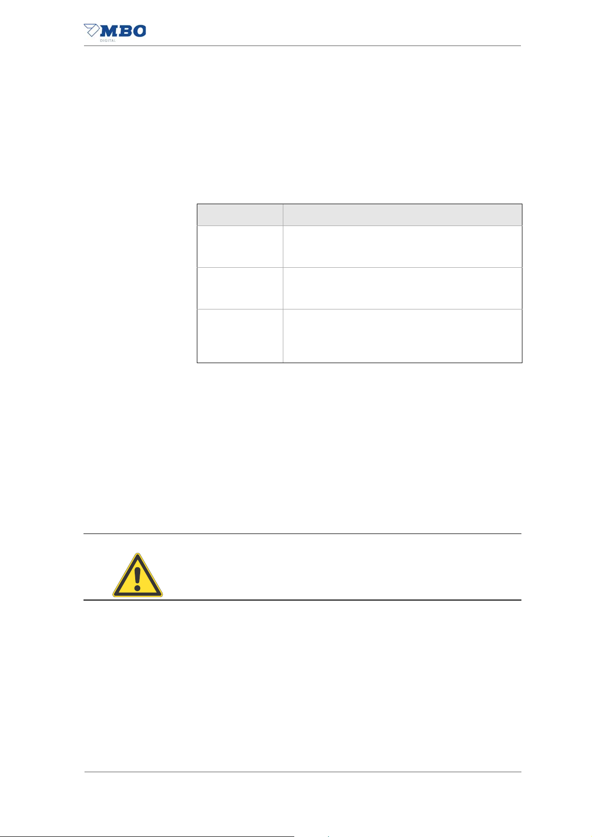
1.4.3 Safety sign
Depiction Meaning
Prohibition sign
Red border, white background, black symbol.
Safety sign that forbids a behavior that could
cause a hazard.
Warning sign
Yellow background, black symbol.
Safety sign that warns about a hazard.
Mandatory sign
Blue background, white symbol.
Table 6: Safety sign
Safety sign that prescribes a particular behavior.
Rescue sign
Green background, white symbol.
Safety sign that identifies the rescue path or
the path to a place where you can get help or
find rescue equipment in case of an emergency.
Fire protection sign
Red background, white symbol.
Safety sign, which in case of hazard marks the
location of fire alarm and fire extinguishing
equipment and/or the path to this equipment.
12
Sheeter SVC 525C
Page 17
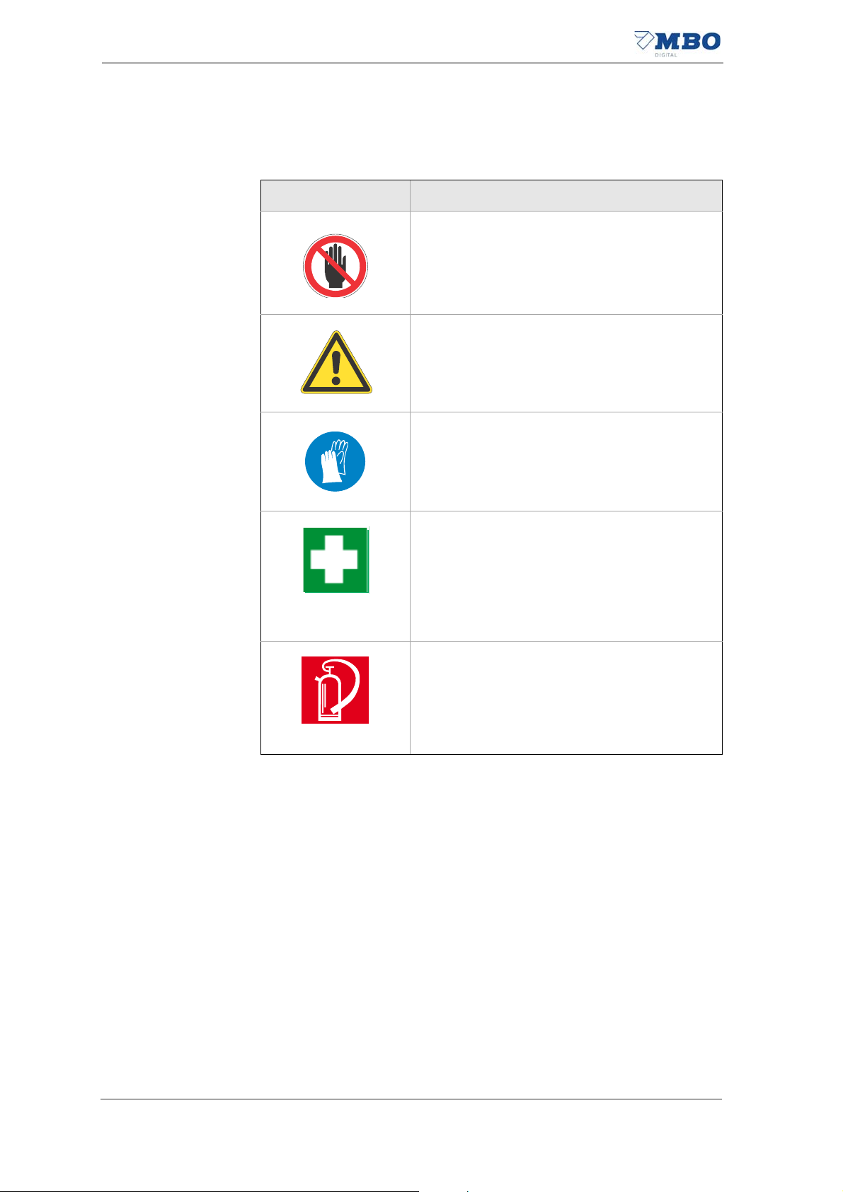
1.4.3.1 Warning sign
About this manual
Description of safety messages
Depiction Meaning
Warning about a general hazard.
You will see this warning-triangle next to activities during which several causes can create
hazards.
Warning of hazardous voltage.
You will see this warning-triangle next to activities during which there is a hazard of electrical
shock, possibly with deadly consequences.
Warning of rotating rollers.
You will see this warning triangle next to activities during which there is a hazard of crushing,
possibly with deadly consequences.
Warning of crushing of hand.
You will see this warning-triangle next to activities during which there is a hazard of crushing
the hand.
Warning of rotating machine parts.
You will see this warning-triangle next to activities during which there is a hazard of cutting
injuries, possibly with deadly consequences.
Warning of lifting heavy machine parts.
You will see this warning triangle next to activities during which there is a hazard of overloading due to lifting heavy loads.
Warning of tipping machine parts.
You will see this warning-triangle next to activities during which there is a hazard of crushing
due to tipping loads.
Warning of entanglement zone.
You will see this warning-triangle next to activities during which there is a entanglement hazard.
Sheeter SVC 525C
Warning of sharp knives.
You will see this warning-triangle next to activities during which there is a hazard of cutting
injuries, possibly with deadly consequences.
Table 7: Warning sign
13
Page 18

About this manual
Description of safety messages
Depiction Meaning
Warning of substances harmful to health.
You will see this warning-triangle next to activities during which there is a hazard of substances harmful to health, possibly with deadly
consequences.
Warning of oxidizing substances.
You will see this warning-triangle next to activities during which there is a hazard of oxidizing
substances, possibly with deadly consequences.
Warning of hot surfaces.
You will see this warning-triangle next to activities during which there is a hazard of burns,
possibly with long-term consequences.
Warning of tripping points.
You will see this warning-triangle next to activities during which there is a tripping hazard,
possibly with deadly consequences.
Table 7: Warning sign
14
Sheeter SVC 525C
Page 19

1.4.3.2 Mandatory sign
Depiction Meaning
About this manual
Description of safety messages
Use hand protection.
You will see this mandatory sign next to activities for which safety gloves should be worn.
Use foot protection.
You will see this mandatory sign next to activities for which safety shoes should be worn.
Use ear protection.
You will see this mandatory sign next to activities for which ear protection should be worn.
Use eye protection.
You will see this mandatory sign next to activities for which eye protection should be worn.
Get help.
You will see this mandatory sign next to activities for which you should ask for the help of
other people.
Follow the operating manual.
You will see this mandatory sign next to activities for which you should follow the operating
manual.
Heed the maintenance chapter.
You will see this mandatory sign next to activities for which you should heed the maintenance chapter.
Activate before maintenance or repair.
You will see this mandatory sign next to activities for which the machine must be de-energized.
Sheeter SVC 525C
Table 8: Mandatory sign
15
Page 20

About this manual
User assessment of the operating manual
1.4.4 Marking of danger spots
Permanent hazards and danger spots are marked with yellow and black
stripes.
Depiction Meaning
Heed danger spot or hindrance.
This hazard marking is affixed to constant danger spots and hindrances.
Table 9: Marking of danger spots
1.5 User assessment of the operating manual
Our operating manuals are updated regularly. Help us with your suggestions for improvement; they make the manuals user-friendly.
16
Sheeter SVC 525C
Page 21

2 Basic safety instructions
The basic requirement for the safe handling and fault-free oper ation of this
machine is knowledge of the basic safety instructions and the safety regulations.
• The operating manual must be heeded by all peo ple who wo rk on or a t
the machine.
• Read and understand the operating manual before working with the machine.
• Always keep the operating manual where the machine is being used.
• The operating manual must always be freely available to the o perating
and maintenance personnel.
• Also heed the applicable accident prevention and environmental protection rules and regulations for the place where the machine is used.
2.1 Intended use
• The machine is intended exclusively for the processing of paper webs.
The specifications relative to format and grammage in the "Technical
data" chapter must be complied with.
• The machine is intended exclusively for one-man operation.
• The machine is intended exclusively for operation in a flawless technical
state.
Any failures that may endanger safety must be remedied immediately
by trained maintenance personnel, or a specialist from the m anu facturer or supplier.
• The machine may only be operated by specially-trained and instructed
personnel.
• The machine may only be operated with the required personal protective equipment.
• Troubleshooting, maintenance and service must be carried out by
trained maintenance personn el only.
• Follow all instructions in this operating manual.
• Heed the local safety regulations and accident prevention regulations.
• Adhere to the inspection and maintenance intervals.
• Use only original wearing parts and spare parts.
Basic safety instructions
Intended use
Sheeter SVC 525C
Use the machine only as intended and when the protective device is
working perfectly.
This is the only way to guarantee the machine's oper at ing saf ety.
17
Page 22

Basic safety instructions
Reasonable foreseeable misuse
2.2 Reasonable foreseeable misuse
Reasonable foreseeable misuses are :
• The processing of materials other than easily tearing webs.
• Operation in an area subject to explosion.
• Operation with removed protective dev ic es .
• Operation of the machine without training or briefing of the operating
personnel.
• Operation of the machine without the required personal protective
equipment.
• Exceeding of the technical values specified for normal operation.
• Individual changes and rebuilding.
• Maintenance and cleaning intervals not adhered to.
• Maintenance and repair work that is not performed correctly.
• Wearing parts not replaced.
• Unintended use.
EMC behavior The electromagnetic compatibility (EMC) of the machine can be impaired
by additions or changes of any kind.
Therefore, do not make any additions or changes to the machine without
consulting the manufacturer and procuring written permission.
Spare and wear parts The use of spare parts and wear pa rts from third -party manufactur ers can
cause risks.
Use only original parts or parts approved by the manufacturer.
The manufacturer assumes no liability for damage from the use of spare
parts and wear parts not approved by the manufacturer.
18
Sheeter SVC 525C
Page 23

2.3 Obligation and liability
The machine is built using the latest technology and according to acknowledged safety rules.
Nonetheless risks and damage can occur when using it:
• to the body and life of the operator or third parties,
• to the machine itself,
• to other property.
If the machine is:
• operated by untrained or uninstructed personnel,
• not used according to its intended use,
• not maintained or not maintained properly or serviced.
The machine is only to be used:
• For the intended use.
• If it is in perfect condition with respect to safety.
Faults that can compromise safety must be remedied immediately.
Basic safety instructions
Obligation and liability
Sheeter SVC 525C
19
Page 24

Basic safety instructions
Warranty
2.4 Warranty
Our "General sales and delivery conditions" apply here.
Warranty and liability claims for personal injury and property damage are
excluded if they are due to one or more of the following causes:
• Non-intended use of the machine.
• Improper assembly, start-up, operation or m aintenance of th e machine.
• Operation of the machine with improperly-mounted or defective protec-
• Failure to follow the instructions in the operating manual with respect to
• Individual constructional changes to the machine.
• Failure to adhere to maintenance and cleaning intervals that exclude a
• Defective monitoring of machine parts that are subject to wear, such as
• Installation of spare and wearing parts that were not ordered from the
• Cases of catastrophe and acts of God.
tive devices.
transport, installation, commissioning, operation, set-up, maintena nce,
and storage of the machine.
breakdown of the machine.
belts, tapes, brushes, and couplings.
manufacturer.
20
Sheeter SVC 525C
Page 25

2.5 Residual risks
A risk analysis with risk assessment was conducted for this machine in accordance with DIN EN ISO 12100:2010.
The construction and model of the machine based on this analysis corresponds to the state of technology.
Y ou ca n avoid residual ri sks by heeding and implementing these spe cifications:
• Safety messages on the machine.
• General safety instructions and special warnings in this operating manual.
• Operating manual of the machine/syst em ma nu fa ctu r er.
• Operator directives.
The existing residual risks are listed in the following chapters according to
the various life phases of the machine.
Basic safety instructions
Residual risks
2.5.1 Transport, interim storage
• Crushing hazard during transport of the machine and machine parts.
• Use of unsuitable fork lifts.
• Tipping machine parts during the unloading process.
• Insufficient properties and condition of the underfloor.
• Wrong interim storage
2.5.2 Set-up, commissioning
• Use of unsuitable fork lifts.
• Tipping machine parts during the installation process.
• Insufficient properties and condition of the underfloor.
• Improper alignment of the machine components.
• Hazardous voltage.
• Incorrect supply voltage
• Incorrect use of the sockets.
• Discharge currents greater than 10mA.
• Disconnected protective conductor connections.
• Dismounted protective devices.
• Tripping points due to connecting cables lying around.
• Operating the sheeter when it is cold.
Sheeter SVC 525C
21
Page 26

Basic safety instructions
Residual risks
2.5.3 Adjustment and operation
• Dismantling, bridging or bypassing protective devices.
• Operation without protective covers.
• Operating the sheeter when it is cold.
• High sound pressure level.
• Rotating machine parts.
• Rotating machine parts in setup mode.
• Cutting hazard due to quickly-running, open web
• Cutting hazard on the longitudinal cutting unit.
• Web break
• Paper jam.
• Tripping points due to connecting cables lying around.
2.5.4 Maintenance
Operational maintenance:
• Rotating machine parts.
• Heavy contamination.
• Improper cleaning
• Unsuitable cleaning agents.
• Incorrect use of cleaning agents.
• Used cleaning cloths.
• Use of compressed air.
• Defective pneumatic lines.
• Incorrect maintenance intervals during multi-shift operation.
Maintenance:
• Hazardous voltage.
• Dismantling, bridging or bypassing protective devices.
• Operation without protective covers.
• Rotating machine parts.
•Crushing.
• Winding up.
• Wrong/poor maintenance tool.
• Improper maintenance.
• Incorrect maintenance intervals during multi-shift operation.
22
Repair:
• Improper repair.
Sheeter SVC 525C
Page 27

2.5.5 Decommissioning, storage
• Incorrect storage.
2.5.6 Disposal
• Improper disposal.
2.6 Product-specific hazards
2.6.1 Entanglement hazard and crushing hazard
The sheeter , due to the transport and cutting process, has rolls, rollers and
knives rotating in opposite directions.
As a result, there is an increased drawn-in hazar d an d cr ushing hazar d in
all setting work.
How to avoid injuries:
Never reach into the machine while the machine is running.
All adjustment or testing/inspection work may be carried out only when
the machine is stopped and secured against switching on.
Press the EMERGENCY STOP palm button.
Adjustment and testing work must always be performed by one person
only.
There is a drawn-in hazard and crushing hazard even when the ma-
chine is in inching mode!
Injuries will be avoided.
Basic safety instructions
Product-specific hazards
2.6.2 Cutting hazard
The longitudinal cut device tools are razor-sharp.
During all work on the tools of the length cut device, there is therefore an
increased cutting hazard on hands and arms, such as when:
• Handling the longitudinal cut device.
• Installing and removing the knives.
• Removing paper jams in the area around the longitudinal cut device.
This is how to avoid cutting injuries:
Never reach towards the knives while the machine is running.
All work on the knives may be carried out only when the machine is
stopped and secured against switching on.
Press the EMERGENCY STOP palm button.
Always wear cut-proof safety gloves and safety shoes when working on
the knives.
Work on the machine must always be performed by one person only.
There is a risk of injury even when the machine is in inching mode.
Cutting injuries will be avoided.
Sheeter SVC 525C
23
Page 28

Basic safety instructions
Life time
2.6.3 Noise
On the sheeter , there is a high noise pressure level at high production
speeds and with heavy papers.
This high sound pressure level can cause hearing damage.
See chapter “3.2.6.1 Geräuschemission”.
This is how to avoid hearing damage:
Always wear ear protection when working on the machine.
Hearing damage will be avoided.
2.7 Life time
2.7.1 Life time of the machine
The life time of this machine is designed for 20 years.
2.7.2 Life time of the control-technical safety components
All components of the control-technical safety circuits have a life time of
more than 20 years.
24
Sheeter SVC 525C
Page 29

2.8 General safety instructions
2.8.1 Transport, interim storage
• Only specially-trained and authorized personnel may transport the machine.
2.8.2 Set-up, commissioning
• Only specially-trained and authorized personnel may set up and commission the machine.
2.8.3 Normal operation
• Only instructed operating personnel may operate the machine.
• The machine may be operated only if all protective devices such as protective hoods and EMERGENCY STOP palm buttons, are present and
fully functional.
• The machine may only be operated with the required personal protective equipment.
• At least once per shift, the machine must also be checked for externallyvisible damage. Changes, including to the operating behavior, must be
reported immediately.
• Machine parts may not be used as climbing aids. If you need to reach
higher-up machine parts, use a suitable working sta ge or other platform.
Make sure that it
spect to height, stability, etc.
corresponds to the safety re quirements, e.g. with re-
Basic safety instructions
General safety instructions
2.8.4 Setting up/equipping
• Only specially-trained and authorized personnel may set up the machine.
• The machine may only be set up with the required personal protective
equipment.
• Inform operating personnel before beginning set-up.
• If the machine is switched off for set-up, it must be secured ag ainst unauthorized or inadvertent switching on again.
Use a padlock to secure the main switch against switching on. If necessary, attach a warning sign to the main switch.
• Machine parts may not be used as climbing aids. If higher machine
parts must be reached, a suitable working stage or other platform must
be used, which fulfills the safety-technical requirements such as height,
stability, etc.
• If larger components or parts are replaced, corr esponding lift equipment
must be used to transport the components. Only use suitable and technically-perfect lift equipment and load suspension devices with suff icient carrying capacity. Secure components and parts so that they
present no hazard.
Do not linger or work under suspended loads.
Sheeter SVC 525C
25
Page 30

Basic safety instructions
General safety instructions
• After completion of the work, do not leave any tools or other loose objects lying on the machine.
2.8.5 Maintenance and repair
• Maintenance and repair work may only be performed by specially
trained technical personnel.
• Maintenance and repair work may only be operated with the required
personal protective equipment.
• Inform operating personnel before beginning service and main tenance
work. Secure the service area if necessary.
• For all repair and maintenance work, heed the switch-on and switch-off
procedures according to the operating manual.
• Heed the prescribed maintenance and maintenance intervals according
to the operating manual.
• If the machine is switched off for service and/or maintenance work, it
must be secured against unauthorized or inadvertent switching on
again. Use a padlock to secure the main switch against switching on. If
necessary, attach a warning sign to the main switch.
• If the dismounting of protective devices is necessary during maintenance and repair work, it must be replaced and checked to make sure
it is functional immediately after completion of the work.
• After completion of the work, do not leave any tools or other loose objects lying on the machine.
• All operating and consumables as well as spare parts no longer needed
must be disposed of safely and in environmentally-appropriate fashion.
2.8.6 Work on electrical equipment
• Only an electrically qualified person is permitted to perform work on the
electrical systems or equipment.
• In case of faults in the electrical power supply, the machine must be
switched off immediately.
• Only use original fuses with the prescribe d am p er age.
26
Sheeter SVC 525C
Page 31

2.9 Personnel, qualification and duties
All activities at or on the machine must be carried out by authorized personnel only.
Authorized personnel is divided into several groups:
• Owner/operator
• Operating personnel
• Maintenance personnel
The authorized personnel must:
• have reached the age of 16,
• know and be able to apply the accident prevention regulations and safety instructions for the machine,
• have read chapter “2 Basic safety instructions” and be able to apply
and implement it in practice,
• be trained and instructed according to the rule s of conduct in the event
of a fault,
• have the physical and mental abilities to carry out his or her responsibilities, tasks, and activities on the machine,
• be trained and instructed in accordance with his or her responsibilities,
tasks, and activities on the machine,
• have understood and can implement practically the operating manual
with respect to responsibilities, tasks, and activities for the machine.
Basic safety instructions
Personnel, qualification and duties
2.9.1 Qualification of the personnel
This table lists the necessary qualification of the personnel related to the
various activities at or on the machine.
Sheeter SVC 525C
27
Page 32

Basic safety instructions
Personnel, qualification and duties
Transportation X- -
Interim storage X--
Set-up --X
Specially trained
personnel
Instructed operating
personnel
Instructed personnel
with specialized training
(mechanical/ electrical
engineering)
Electrical
--X
connections
Stationary mains
--X
connection
Commissioning --X
Troubleshooting
(mechanical/electrical
--X
Installation, set-up XX-
Operation -X-
Operational mainte-
-X-
nance (cleaning)
Maintenance X-X
Repair --X
Decommissioning --X
28
Storage X--
Disposal X--
Table 10: Qualification of personnel
Legend: X permitted, - not permitted
Sheeter SVC 525C
Page 33

2.9.2 Duties of the operator
The owner/operator is responsible for
• the machine being operated only as intended,
• the machine being operated only when it is fully functional, safe and reliable,
• the machine being maintained and cleaned according to the specifications in the maintenance and cleaning schedule,
• the machine is protected against unauthorized use,
• the necessary personal protective equipment being available,
• the necessary personal protective equipment being worn,
• only authorized personnel having access to the machine,
• the authorized personnel being adequately qualified,
• the authorized personnel being instructed in all applicable questions of
workplace safety, accident prevention, and environmental protection,
• the authorized personnel has read and understood the operating manual,
• the operating manual is always kept where the machine is used and it
is freely accessible to the operating and maintenance personnel,
• the safety and notice signs on the machine are kept in an easily legible
condition,
• a risk assessment of the entire system being carried out and its results
being summarized in an operator directive,
• identified defects or abnormal operating states/jams being remedied immediately,
• operation of the machine being ceased during troubleshooting.
Basic safety instructions
Personnel, qualification and duties
Heed the national laws and European directives abou t occupational safety
and health of employees at work.
Germany The requirements of the German Labor Protection Act (ArbSchG) and the
German Health and Safety at Work Regulations (BetrSichV) must be adhered to.
EC countries The requirements of the directives 89/391/EEC and 2009/104/EU must be
adhered to.
Sheeter SVC 525C
29
Page 34

Basic safety instructions
Personnel, qualification and duties
2.9.3 Duties of the operating personnel
The operating personnel must:
• be trained and instructed,
• use the machine as intended,
• wear the necessary personal protective equipment,
• observe the basic regulations regarding workplace safety a nd accident
prevention,
• read and heed the chapter “2 Basic safety instructions” and the safety
messages in this operating manual,
• immediately take the machine out of operation in the event of defects or
abnormal operating states/malfunctions,
• immediately report any identified defects or abnormal operating states/
malfunctions.
The operating personnel is responsible for
• ensuring that the machine is protected against unauthorized use,
• ensuring that the machine is operated only when it is fully functional,
safe and reliable,
• cleaning is performed according to the cleaning plan.
2.9.4 Duties of the maintenance personnel
The maintenance personnel must:
• be trained and instructed,
• use the machine as intended,
• wear the necessary personal protective equipment.
The maintenance personnel is responsible for
• protecting the machine against unauthorized use,
• the maintenance being carried out according to the maintenance schedule.
30
Sheeter SVC 525C
Page 35

2.10 Personal protective equipment
2.10.1 Operation and adjustment
This personal protective equipment must be provided and worn for the operation and set-up of the machine:
• Ear protection
• Cut-resistant safety gloves
• Safety shoes
Basic safety instructions
Personal protective equipment
2.10.2 Operational maintenance (cleaning)
This personal protective equipment must be provided and worn for the
proper maintenance (cleaning) of the machine:
• Safety shoes
• Cut-resistant safety gloves
Sheeter SVC 525C
31
Page 36

Basic safety instructions
X
Unit of measurement in cm
1
Work areas and workstations
2.11 Work areas and workstations
• The machine is intended exclusively for operation by one person.
• The figure shows the most important workstations as well as the working area and service area of the machine.
• The necessary work areas for operation, installation, commissioning,
and maintenance are highlighted in gray and should be at least 100 cm.
• The service area is marked with hatching.The possible workplaces are
marked with an "X".
2.1 1.1 Layout from right to left
1 Workstation
Illustration 1: Work area and workstation SVC 525C
32
Sheeter SVC 525C
Page 37

Basic safety instructions
2.12 Markings on the machine
These markings must be on the machine and in an easily legible co ndition.
If the markings are damaged or illegible, they must be replaced.
For the appropriate MBO part number, see chapter “2.12.1 Position and
meaning”.
2.12.1 Position and meaning
Pos. 1 MBO part number:10.5171.025
Markings on the machine
Meaning: Name plate
Illustration 2: Name plate
Pos. 2 MBO part number: 10.5171.026
Meaning: Electric name plate
Illustration 3: Electric name plate
Sheeter SVC 525C
33
Page 38

Basic safety instructions
Markings on the machine
Pos. 3 MBO part number:4002643
Meaning: <Read operating manual> mandatory sign
Illustration 4: <Read operating manual> mandatory sign
Pos. 4 MBO part number:4002562
Meaning: <Wear ear protection> mandatory sign
Illustration 5: <Wear ear protection> mandatory sign
Pos. 5 MBO part number:4003327
Meaning: <Drawn-in hazard> warning sign
Illustration 6: <Drawn-in hazard> warning sign
34
Sheeter SVC 525C
Page 39

Pos. 6 MBO part number: 0100699
Meaning: <Hot surface> warning sign
Illustration 7: <Hot surface> warning sign
Pos. 7 MBO part number: 4003326
Basic safety instructions
Directions for emergencies
Meaning: <Crushing hazard> warning sign
Illustration 8: <Crushing hazard> warning sign
Pos. 8 MBO part number: 0128301
Meaning: <Hazardous voltage> warning sign
Illustration 9: <Hazardous voltage> warning sign
2.13 Directions for emergencies
The operator must add instructions regarding national regulati ons for accident prevention to this operating manual.
Sheeter SVC 525C
35
Page 40

Basic safety instructions
Directions for emergencies
2.13.1 Emergency call numbers
Police
European Union
Fire department
Ambulance
Police
Germany
Fire department
Ambulance
Police
USA
Fire department
Ambulance
Police
China
Fire department
Ambulance
Table 11: Emergency call numbers
2.13.2 Behavior in case of accidents
1 Immediate measures
• Stay calm.
• Secure the accident location.
• Heed your own safety.
• If necessary , rescue person from th e danger zone.
• Check consciousness and breathing/check for
type of injury.
• If necessary, take lifesaving measures right away.
112
112
112
110 or 112
112
112
911
911
911
110
119
120
2 Emergency call
3 First aid
Table 12: Behavior in case of accidents
• Where is the accident location?
• What happened?
• How many injured?
• What injuries?
• Who's calling?
• Wait for queries!
• Provide help as necessary.
• Check consciousness and breathing.
• Protect against heat loss.
• Provide support and assistance.
36
Sheeter SVC 525C
Page 41

3 Product description
3.1 Important notices about the product
3.1.1 View
Product description
Important notices about the product
Illustration 10: Overall view
3.1.2 Standard equipment
• Completely automatic conversion of format and chip-out.
• Variable format length up to a maximum of 2.032 mm.
• Variable chip-out possible (4 - 80 mm).
• External length cut cassette.
• Air-assisted sheet running.
• Discharge table, foldable.
• Window function.
3.1.3 Options
• Gully cut in longitudinal direction SVC-GC.
• Interfaces (digital printer, folding machines).
• Print mark control software (watchdog).
Sheeter SVC 525C
37
Page 42

Product description
Unit of measurement cm
Technica l data
3.2 Technical data
3.2.1 Floor plan
3.2.1.1 Layout from right to left
Illustration 11: Floor plan SVC 525 C, right to left
38
Sheeter SVC 525C
Page 43

3.2.2 Performance characteristics
Product description
Technical data
Speed Minimum
Maximum
7 m/min 250 m/min
Web format width
Grammage
2)
Cutting accuracy Longitudinal cut
Cross-cut
Lateral web guide
150 mm 520 mm
40 g/m
2
250 g/m
± 0.5 mm
± 0.5 mm
± 0.2 mm
accuracy
Format lengths
Continuously variable 76 mm 2,032 mm
Continuously variable with
127 mm 2,032 mm
chip out
Chip-out sizes Without chip-out
Continuously variable
Table 13: Performance characteristics
1) The maximum working speed depends on paper properties, format, fold type, temperature, and humidity, as well
as various states at the operator that the manufacturer cannot influence.
2) All values refer to simple volume paper.
0mm 4mm 80mm
1)
2
Sheeter SVC 525C
39
Page 44

Product description
Technica l data
3.2.3 Shipping and transport data
Weight Net Gross
Without packaging Approx. 1380 kg With shipping pallet - Approx. 1500 kg
With shipping crate - Approx. 1700 kg
Dimensions
L x W x H
Without packaging 180 x 160 x 133 (cm)
With shipping pallet 200 x 180 x 175 (cm)
With shipping crate 205 x 185 x 180 (cm)
Fork lift
1)
Carrying capacity / load (Q)
2)
Min. 2000 kg
Fork tine length Min. 150 cm
Floor conditions
Table 14: Shipping and transport data
1) Minimum requirements of the fork lift
2) Heed operating manual for the fork lift, load capacity depends on the load center of gravity (c).
3) Minimum load capacity of the floor where the machine will be set up
4) In the area of the machine, the total height difference may not exceed 20 mm.
3)
Cargo
Levelness
> 20 kN/m
4)
< 10 mm/m
2
40
Sheeter SVC 525C
Page 45

3.2.4 Electrical supply
Product description
Technical data
Electrical supply
1)
Nominal voltage
3 x 400 V + N + PE
Connecting line
2)
4)
Fuse
Protective equipotential
bonding conductor
5)
Wiring diagram no. See electrical name pla te
Required mains configu-
3)
ration
TN - C - S power mains
Clockwise rotating field required
TN - S - power
Voltage 400 V AC +/-10%
Frequency 50Hz +/-1%
Control voltage: 24 VDC/10 A
Cross-section (IEC)
mm
2
Cross-section (UL)
Max. line length m
Min. network impedance mOhm
Short-circuit current rating
6kA
(SCCR) according to UL
508A
IEC 63 A characteristic C
UL 63 A
Cross-section according
10 mm
2
to IEC
Connected loads
Operational readiness
(stand-by)
Tab le 15: Electrical supp ly 400V network
1) Stationary mains connection
2) If the existing nominal voltage varies from the supply voltage specified above, an isolating transformer must be installed.
If the nominal voltage is 380 V or 415 V at 50 Hz, the tolerance of the power mains must be checked.
If the tolerance is between 360 V – 440 V, an isolating transformer is not required.
3) N - line is loaded; a fault-current circuit breaker (FI) may not be used.
4) According to EN ISO 60204:2006 Table 10.
5) According to EN 60204:2006.
6) The total connected load depends on the number and equipment of the connected machines.
6)
Total
Power kW
Current rate A
Approx. 14 kW
Sheeter SVC 525C
41
Page 46

Product description
Technica l data
3.2.5 Compressed air supply
Compressed air supply
Connected loads
Necessary network pressure
Average consumption
Quality:
Connecting line
Table 16: Compressed air supply
1) Required volume flow according to ISO 1217 or DIN 1945
2) Corresponds to ISO 8573-1 Class 5
3) According to ISO 8573-1
Connection type PK 6 hose with qu ick opening device
1)
6 bar +1 bar
60 l/min
Filter unit 40 µm
Dried and oiled
2)
3)
3.2.6 External extraction system (to be provided by the customer)
External extraction system
Suction power
Connection type
Volume
1800 m
Flow speed 25 m/sec
1)
Edge trim 2 x open tube with 50 mm diameter
3
/h
Gully cut
1 x open tube with 50 mm diameter
(optional)
Chip-out Open tube with 100 mm diameter
Table 17: External extraction system
1) Optionally a collection system can be provided, to which all internal machine suction hoses are connected. The
connection to the external extraction system is then made with a single open tube with a 150 mm diameter.
42
Sheeter SVC 525C
Page 47

Product description
Technical data
3.2.7 Emissions
3.2.7.1 Noise emissions
Noise emissions
Specified two-digit noise emissions value according to DIN EN 4871 Idling Load
A-weighted sound power level L
Uncertainty K
WA
in dB
A-weighted emission sound pressure level L
In dB re 20 Pa at the operating place
Uncertainty K
WA
in dB
in dB re 1 pW
WA
PA
-
-
<70
2.5
99
2.5
79
2.5
The values were determined in accordance with the noise emission standard DIN EN ISO 13023
1)
using the basic standards DIN EN ISO 3746 and DIN EN ISO 11204
Tab le 18: Noise emissions
1) Noise measurement EN 13023 F.2 - class 2
3.2.8 Ambient conditions
Room temperature
Storage temperature
Relative humidity
Set-up height
2)
Optimal
Minimum
Maximum
17 ... 35 °C
10 ... 35 °C
40 - 60 %
30 %
80 % (non-condensing)
Max. 800 above sea level
1)
Tab le 19: Ambient conditions
1) At temperatures below or above the permissible room temperature, special measures must be taken.
2) For installation at an altitude of 800 m above sea level or higher, special measures are necessary for the pressure
vacuum pumps.
Learn more about this from the manufacturer.
Sheeter SVC 525C
43
Page 48

Product description
Technica l data
44
Sheeter SVC 525C
Page 49

4 Structure and function
1
2
3
4
In this chapter you will find a description of the components and function
of the sheeter.
4.1 Structure
4.1.1 Components of the sheeter
The components are distributed across the four sides of the sheeter.
Structure and function
Structure
1 Control cabinet side
2 Infeed side
Illustration 12: Views of the sheeter
Sheeter SVC 525C
3 Operator side
4 Outfeed side
45
Page 50

Structure and function
2
1
Structure
4.1.1.1 Components of the control cabinet side
1 Control cabinet 2 Connection of extraction device for chip-out
Illustration 13: Components of the control cabinet side
46
Sheeter SVC 525C
Page 51

4.1.1.2 Components of the infeed side
1
2
3
4
7
8
6
5
Structure and function
Structure
1 Temperature regulation, cutting unit
2 Main switch
3 Fan, control cabinet
4 Transport rollers
Illustration 14: Components of the infeed side
5 Adjustable feet
6 Suction device, longitudinal cutting device
7 Infeed table with longitudinal cutting device
8 Manometer, nip rollers
Sheeter SVC 525C
47
Page 52

Structure and function
2
3
4
5
1
Structure
4.1.1.3 Components of the operator side
1 Protective hood with guard locking
2 Pressure regulator for nip rollers
3 Touchscreen
Illustration 15: Components of the operator side
4 Control panel
5 Guard door with guard locking
48
Sheeter SVC 525C
Page 53

4.1.1.4 Components of the outfeed side
1
2
3
4
5
Structure and function
Structure
1 Waste sheet deflector
2 Adjustable feet
3 Conveyor table, foldable
Illustration 16: Components of the outfeed side
4 Transport rolls
5 Fan, control cabinet
Sheeter SVC 525C
49
Page 54

Structure and function
2
3
1
Format A
Format B
Format C
Format D
Format A
Format B
Format C
Format D
Format A
Format B
Format C
Format D
Functional description
4.2 Functional description
The SVC525C sheeter is a completely electronically-controlled sheeter
with variable and infinite adjustment with respect to format and chip out
size.
The sheeter can either be operated in-line (i.e. after a digital printer) or offline (with its own unwinder).
4.2.1 Cutting sequences
Illustration 17: Cutting sequences
4.2.2 Control panel
The following cutting sequences are possible:
1 Sequential cutting: Multiple formats (max. 6) and 1 chip-out in one sequence
(max. 2 m).
2 Sequential cutting: Multiple formats (max. 6) and multiple chip-outs in one
sequence (max. 2 m).
(The number of maximum possible chip-outs is limited by the mechanical setting in the chip-out disposal).
3 Fully variable cutting: Cut is made from print mark to print mark in a different
sequence with constant chip-out.
The control panel with EMERGENCY STOP palm button provides the control functions.
The touchscreen is used to adjust the sheeter unit.
50
Sheeter SVC 525C
Page 55

4.3 Infeed table
Infeed rolls The infeed rolls introduce the web into the sheeter.
The infeed position of the web changes according to the upstream machine.
Structure and function
Infeed table
Longitudinal cut
cassette
The longitudinal cut cassette is used for cutting (principle of rotating scissor
cutting) of the web fed in for:
• Edge trim.
An external extraction system is required for this.
• Separator cut
• Gully cut (optional).
An external extraction system is required for this.
4.3.1 In-feed unit
Sensor <Web break> The <Web break> sensor detects a web break in front of the first in-feed
shaft and stops the sheeter.
First in-feed shaft The first in-feed shaft with the nip rollers fixes the web for the previous ma-
chine.
It turns at the web speed.
Sensor <Print mark> The <Print mark> sensor detects the print marks on the web and controls
the setting made accordingly, the position of the cross-cuts for the format
and the chip-out.
Sensor <Paper jam> The <Paper jam> sensor stops the sheeter if there is a jam between the
first in-feed shaft and the second in-feed shaft.
Second in-feed shaft The second in-feed shaft transports the web into the sheeter unit.
It turns approx. 11% faster than the first in-feed shaft.
Sheeter SVC 525C
51
Page 56

Structure and function
1
2
Format
Chip-out
3
4
Infeed table
4.3.2 Sheeter unit
Cutting principle
Illustration 18: Cutting principle
Production without chip-out (3):
• the upper cutting cylinder (1) cuts the format.
• the lower cutting cylinder (2) is stationary in its resting position.
Production with chip-out (4):
• the lower cutting cylinder (2) cuts the format (= chip-out + format).
• the upper cutting cylinder (1) cuts the chip-out off the front edge of the
format.
Heated side walls • In order to maintain a constant temperature and achieve perfect cut
quality, the side walls of the sheeter unit are actively heated.
• Heating begins when the main switch is switched on.
• The duration of the warm-up phase depends strongly o n the respective
ambient temperature.
At an ambient temperature of 18°C, this is approx. 15-20 min.
To ensure that the entire cutting unit is heated evenly, a warm-up
phase of one hour should be observed. This avoids increased
wear on the cutting units.
• If a temperature of 33°C is not reached, producti on is not enabled. This
is indicated by a message on the touchscreen .
• Never operate the sheeter when the set temperature has not yet been
reached, otherwise this could result in serious property damage.
• A fluctuation on the temperature indicator during operation is normal
and is caused by the set hysteresis characteristic curve.
52
Sheeter SVC 525C
Page 57

Structure and function
4.3.3 Discharge table
Short belt table The short belt table serves as a transport route from the upper cutting cyl-
inder to the waste sheet deflector.
It runs approx. 2% faster than the second in-feed shaft.
Variants
Waste sheet
deflector
Long belt table The long belt table serves as a transport route to the downstream machine.
The waste sheet deflector discharges waste sheets during set-up.
For the discharge of waste sheets that arise during production, the discharge module EM770 is used.
It is designed to fold up so that settings can be made on the sheeter without
taking the system apart.
4.3.4 External extraction system
The external extraction system is required for th e disposal of the cut pap er
strips in the longitudinal cutting unit (edge-trim, gully cut) as well as the chip
outs from the sheeter unit.
The extraction system should be equipped with a shut-of f device so that the
air quantity can be set individually.
For technical data, see Chapter “3.2.6 External extraction system (to be
provided by the customer)”.
4.3.5 Compressed air connection
The compressed air connection is made via an external compressed air
hose (PK 6 – hose with quick-action locking piece).
This is required for:
• Activation of the nip rollers on the in-feed shafts.
• Air-assisted sheet running in the sheeter unit.
4.4 Variants
4.4.1 Variant SVC 525 C
Definition of terms:
Sheeter SVC 525C
The designation „SVC 525 C" means:
SVC
525
C
Type designation, sheeter
Maximum web width 520 mm
With second cutting cylinder for the chip-out
53
Page 58

Structure and function
Protective devices
4.5 Protective devices
4.5.1 Definition of terms
4.5.1.1 Fixed guards
Fixed guards:
• are used if access to the area secured by the protective device is seldom or never required.
• must only be loosened or removed using tools.
• do not have any electric locking (safety switch).
4.5.1.2 Interlocking movable guards
Interlocking movable guards:
• are used if access to the area secured by the protective device is frequently required.
• can be opened without tools.
• have electric locking (safety switch).
When the protective device is opened, this causes the machine to stop.
The machine can be restarted only after the protective device is closed.
4.5.1.3 Interlocking movable guards with guard locking
Interlocking movable guards with guard locking:
• cannot be opened when the machine is operating.
The locking prevents access to the danger spot until the hazardous
function has been eliminated.
• can be opened without tools.
• have electric locking (safety switch) and a locking.
When the protective device is lifted, the electric locking causes the ma-
chine to stop.
Only when the hazardous function has been eliminated safely is the
locking reset and then the protective device can be opened completely.
The machine can be restarted only after the protective device is closed.
54
Sheeter SVC 525C
Page 59

4.5.2 Overview
1
2
3
Structure and function
Protective devices
Operate the machine only if all protective devices are completely present and fully functional!
The following protective devices are present on the machine.
1 Protective hood with guard locking
2 Guard door with guard locking
Illustration 19: Overview
3 EMERGENCY STOP palm button
Sheeter SVC 525C
55
Page 60

Structure and function
1
1
Protective devices
4.5.3 Protective hood with guard locking
1 Protective hood with guard locking
Illustration 20: Protective hood with guard locking
• The protective hood prevents intervention in the in-feed area and in
the cross-cutting area of the machine.
• It is fitted with a guard locking.
This means that the protective hood can only be opened after th e secure stopping of the machine.
How to open the protective hood:
Lift and hold the protective hood.
The machine stops.
After detection of the secure stop, the guard locking is unlocked.
The protective hood can now be opened completely.
The protective hood is open.
4.5.4 Guard door with guard locking
1 Guard door with guard locking
Illustration 21: Guard door with guard locking
56
•The guard door prevents interventi on in the drive area of the machine.
•The
guard door is fitted with guard locking.
In other words, the
guard door can only be opened when the protective
hood is open.
Sheeter SVC 525C
Page 61

4.5.5 EMERGENCY STOP palm button
1
2
1 EMERGENCY STOP palm button
2 <Reset EMERGENCY STOP> illuminated button
Illustration 22: EMERGENCY STOP palm button
Structure and function
Protective devices
• To prevent immediate or potential hazards, the machine is equipped
with an EMERGENCY STOP shut-off device.
• After the <EMERGENCY STOP> palm button is pressed, all electri-
cal drives are switched off.
• EMERGENCY STOP does not disconnect the machine from the
electrical supply.
The machine is in operation.
There is a hazardous situation and the machine must be stopped quickly.
Procedure:
Press the EMERGENCY STOP palm button (1).
The <Reset EMERGENCY STOP> light (2) lights up.
Eliminate the failure.
Disengage the EMERGENCY STOP palm button (1) by turning it to the
right.
Activate the <Reset EMERGENCY STOP> illuminated button (2).
The <Reset EMERGENCY STOP> light (2) does not come on.
The machine is ready for operation.
Note that:
• When the EMERGENCY STOP palm button is pressed, the entire
system is stopped immediately.
• To restart the entire system, a special switch-on sequence must be
carried out.
• After restarting the system, an automatic pallet change is carried out
in the high pile stacker.
Sheeter SVC 525C
57
Page 62

Structure and function
Protective devices
4.5.6 Guards
There are other fixed guards present on the machine.
These protect the operator against danger spots such as:
• rotating machine parts, e.g., drives, shafts
• entanglement zones
• pinch points
The function and position of the corresponding protective devices are listed
in the "Protective devices" check list.
See chapter “4.5.9 Checklist for protective devices”.
4.5.7 Faulty protective devices
Faulty protective devices can lead to hazardous situations.
For this reason:
Switch off the machine at the main switch immediately.
Secure it against being switched on again.
If necessary, disco nnect the supply of compressed air and electrical cur-
rent.
Service faulty protective devices immediately.
4.5.8 Checking protective devices
All protective devices must be checked regularly.
For the corresponding inspection interv a l s, see chapter “4.5.9 Checklist
for protective devices”
For the corresponding procedure, see the Maintenance chapter.
58
Sheeter SVC 525C
Page 63

4.5.9 Checklist for protective devices
1 2
5
3
4
6
Use this checklist to check the machine protective devices regularly.
Structure and function
Protective devices
Visual
inspection
Result
Inspection
interval
Daily
Pos. Designation
1 Protective hood with safety
Functioning control
switch and guard locking
2 Guard Weekly
3 Guard, in-feed drive Weekly
4 Guard, in-feed Weekly
5 Guard door with guard locking Daily
6 EMERGENCY STOP palm but-
Daily
ton
Date: Name: Signature:
Table 20: Checklist for protective devices
Sheeter SVC 525C
59
Page 64

Structure and function
1
6
2
3
5
4
7
8
Protective devices
Visual
inspection
Result
Inspection
interval
Pos. Designation
Functioning control
1 Guard, out-feed Weekly
2 Guard, out-feed Weekly
3 Guard Weekly
4 Guard Weekly
5 Guard below in-feed shafts Weekly
6 Guard, in-feed Weekly
7 Guard, in-feed Weekly
8 Guard, out-feed Weekly
Date: Name: Signature:
Table 21: Checklist for protective devices
60
Sheeter SVC 525C
Page 65

Structure and function
1
23
4
Protective devices
Visual
inspection
Result
Inspection
interval
Pos. Designation
Functioning control
1 Guard, conveyor table Weekly
2 Guard, conveyor table Weekly
3 Guard, conveyor table Weekly
4 Guard, conveyor table Weekly
Date: Name: Signature:
Table 22: Checklist for protective devices
Sheeter SVC 525C
61
Page 66

Structure and function
Protective devices
62
Sheeter SVC 525C
Page 67

Operating and display elements, operating modes
I
0
1
2
Main switch
5 Operating and display elements, operating modes
5.1 Main switch
1 Main switch OFF 2 Main switch ON
Illustration 23: Main switch
The main switch has the following properties:
• It disconnects the sheeter from the electrical supply.
• It disconnects the machines connected to the sheeter from the electrical
supply.
• It has only one OFF and one ON position, labeled 0 and I.
• It is equipped with a device that enables it to be locked in the OFF position (e.g. by a padlock).
Switching off the main switch also switches off the heaters of the cutting
units.
After switching on the main switch, observe the necessary warm-up
phase of the heaters.
Sheeter SVC 525C
63
Page 68

Operating and display elements, operating modes
15
1
2
3
4
5
67
89
10
1112
13
14
Control panel
5.2 Control panel
Illustration 24: Control panel
1 EMERGENCY STOP palm button
2 Not assigned
3 Not assigned
4 Not assigned
5 <Not ready for operation> <Jam> light
6 <Speed adjustment, conveyor table> potentiometer
7 <Nip rollers on/off> illuminated selector switch
Position left = off.
Position right = on, illuminated selector switch lights up.
8 <Air 2> adjusting element
Web is lifted to the upper cutting cylinder.
9 <1> adjusting element
Blow out chip-out.
10 <Air 3> adjusting element
Web is held down on the upper cutting cylinder.
11 <Inching> button
12 <Stop> button
13 <Start> button
14 <Reset EMERGENCY STOP> illuminated button
15 Not assigned
64
Sheeter SVC 525C
Page 69

5.3 Touchscreen
1
5.3.1 Usage
• Only use your finger or a stylus pen (MBO part number 01 31900 ) to
operate the touch pen (1).
• Ball-point pens or other metallic objects may damage the surface of
the touchscreen.
Operating and display elements, operating modes
Touchscreen
Illustration 25: Usage of the touchscreen
Sheeter SVC 525C
65
Page 70

Operating and display elements, operating modes
1
2
4
5
3
6
Touchscreen
5.3.2 Structure of the pages
Illustration 26: Structure of the pages
All pages are equipped with these basic func tion s:
1 <Page selection> selector switches.
2 Current page content display
3 <Password> keypad.
4 <Reset EMERGENCY STOP> button
5 <Error messages / status information> info box
6 Image number/user code
66
Sheeter SVC 525C
Page 71

Operating and display elements, operating modes
1
2
3
4
5
12
5.3.2.1 <Page selection> selector buttons
Illustration 27: Page selection
The following selector buttons are available:
1 <Format setting> button.
Pressing the <Format setting> button displays the <Format setting> page.
See chapter “5.3.4.2 <Format setting> page”.
2 <Recipe management> button.
Pressing the <Recipe management> button displays the <Recipe
management> page.
See chapter “5.3.4.3 <Recipe management, load stored recipes> page”.
3 <Service> button.
Pressing the <Service> button displays the <Service> page.
See chapter “5.3.4.5 <Service> page”.
4 <Info> button.
Pressing the <Info> button displays the <Info> page.
See chapter “5.3.4.2 <Format setting> page”.
5 <Home / Back> button.
Pressing the <Home / Back> button displays the <Start page> page.
See chapter “5.3.4.1 <Start page> page”.
Touchscreen
5.3.2.2 Error messages / status information info boxes
Illustration 28: Info boxes
1 <Status information> info box
Status information is displayed as black text on a green background.
2 <Error messages> info box
Error messages are displayed as black text on a red background.
Sheeter SVC 525C
67
Page 72

Operating and display elements, operating modes
1
2
1
Touchscreen
5.3.2.3 <Password> keypad
Illustration 29: <Password> keypad
1 <Password> keypad (1).
Pressing the keypad opens the <Password input> page.
2 <Password input> page (2 ) .
Entering specific passwords enables defined functions for reading and
adjustment on the <Service> page.
Changes to password-protected functions on the <Service> page are
only permitted to be carried out by MBO Service or by an authorized cu stomer service representative.
5.3.2.4 <Reset EMERGENCY STOP> button
Illustration 30: <Reset EMERGENCY STOP> button
1 <Reset EMERGENCY STOP> button
After unlocking the <EMERGENCY STOP palm button>, the <Reset
EMERGENCY STOP> button must be pressed twice.
68
Sheeter SVC 525C
Page 73

5.3.3 Structure of the pages
Operating and display elements, operating modes
Touchscreen
Illustration 31: Structure of the pages
Sheeter SVC 525C
69
Page 74

Operating and display elements, operating modes
1
8
2
3
4
5
6
7
Touchscreen
5.3.4 Description of the pages
5.3.4.1 <Start page> page
This page displays the current production data.
Illustration 32: Start page
1 <Job> display.
Displays the designation of the current job.
2 <Configuration> display.
Displays the designation of the current configuration.
3 <Actual speed> display.
Displays the current actual speed of the machine.
4 Buttons <V-> and <V+>.
Pressing the <V-> or >V+> button reduces or increases the speed in
increments.
5 <Set speed> display.
Displays the current set speed of the machine.
6 <Job speed> button.
Pressing the <Job speed> button opens a number input field. A new job
speed can be entered in this input field.
7 <Job speed> display.
Displays the current job speed.
8 <Animation graphic> display.
Displays the current cutting process in graphics.
70
Sheeter SVC 525C
Page 75

5.3.4.2 <Format setting> page
7
1
3
4
2
6
5
This page is used to enter the format data.
Operating and display elements, operating modes
Touchscreen
Illustration 33: Format setting
1 <Length unit> notice.
All displayed and entered lengths are in mm.
2 <Number of sheets> input field.
Pressing the <Number of sheets> input field opens a number input field. The
required number of sheets can be entered in this field.
3 <Number of chip-outs> input field.
Pressing the <Number of chip-outs> input field opens a number input field.
The required number of chip-outs can be entered in this field.
4 <Max. speed> display.
Displays the current job speed.
5 <Format length> input field.
Pressing the <Format length> input field opens a number input field. The
required format length is entered into this field.
6 <Chip-out1> input field.
Pressing the <Chip-out1> input field opens a number input field. The required
length of chip-out 1 is entered into this field.
7 <Sheet1> input field.
Pressing the <Sheet1> input field opens a number input field. The required
length of sheet 1 is entered into this field.
Sheeter SVC 525C
71
Page 76

Operating and display elements, operating modes
8
1
3
2
7
6
5
4
Touchscreen
5.3.4.3 <Recipe management, load stored recipes> page
Stored recipes (jobs) can be selected on this page and loaded into the control system
Illustration 34: <Recipe management, load stored re cipes
1 <Selection list display> button .
After the button is pressed, all stored recipes (jobs) are listed in a display
field.
Select the required recipe by tapping the touchscreen.
The name of the selected recipe is displayed in the <Current recipe> (7)
display field.
2 <Scroll one row up> button.
This makes it possible to scroll through the <Parameter list> (4) display field.
3 <Scroll one row down> button.
This makes it possible to scroll through the <Parameter list> (4) display field.
4 <Parameter list> display field.
Displays the individual parameters of the selected recipe.
5 <Send> button.
The data for the displayed parameter list is sent to the control system.
6 <Load> button.
The data for the selected recipe is displayed in the <Parameter list> (4)
display field.
7 <Current recipe> display field.
Displays the name of the current recipe.
8 <To next page> button.
Pressing the button displays the <Recipe management, create new recipes>
page.
72
Sheeter SVC 525C
Page 77

Operating and display elements, operating modes
7
1
6
5
4
3
2
5.3.4.4 <Recipe management, create new recipes> page
The following can be carried out on this page:
• Stored recipes (jobs) can be selected and loaded onto the control system.
• New recipes created and stored.
• Stored recipes deleted.
Touchscreen
Illustration 35: Recipe management, create new recipes
1 <Parameter list> display field.
Displays the data for the selected recipe.
2 <Delete> button.
The recipe displayed in the display field (6) is deleted.
3 <Save> button.
The new recipe created (job) is saved with the data displayed for the
parameter list (1).
4 <Create new job> button.
A new recipe (job) is displayed in the display field (6).
The suggested name (r?) can be changed by tapping (alphanumeric
keypad).
5 <Upload data> button.
The current data of the control system is loaded into the <Parameter lists>
display field.
6 <Current recipe> display field.
Displays the name of the current recipe.
7 <To next page> button.
Pressing the button displays the <Recipe management, load stored recipes>
page.
Sheeter SVC 525C
73
Page 78

Operating and display elements, operating modes
1
5
6
3
4
2
Touchscreen
5.3.4.5 <Service> page
Other service pages can be selected on this page.
Illustration 36: <Service> page
1 <Service> keypad.
Different settings can be made in the <Service> keypad.
See chapter “5.3.4.6 <Service keypad> page”
2 <Manual control> button.
The button is password-protected.
If the password protection is removed, the machine can be controlled
manually via the touchscreen.
3 <Machine parameters> button.
The button is password-protected.
If the password protection is removed, settings can be made to the
parameters on the machine.
4 <System settings> button.
The button is password-protected.
If the password protection is removed, settings can be made for the
machinery.
5 <Display settings> button.
The button is password-protected.
If the password protection is removed, settings can be made for the display.
E.g.: Selecting the language.
6 <Diagnosis> button.
The button is password-protected.
If the password protection is removed, certain functions can be diagnosed.
Changes to the password-protected functions are only permitted to be
carried out by MBO Service or by an authorized customer service representative.
74
Sheeter SVC 525C
Page 79

5.3.4.6 <Service keypad> page
1
2
3
4
Illustration 37: <Service keypad>
Operating and display elements, operating modes
Touchscreen
1 <Calibration > area.
<Calibrate drives> button
2 <Print mark> area.
<Print mark control> button
<Teach print mark> button
<Print mark mean value> button.
3 <Print mark offset> area.
<+> button
<-> button.
<Print mark offset> display
<Length warm-up frame> display
4 <General> area.
<Outer sensor active> button
<Jam sensor outfeed> button
<No paper> button
<Waste paper control> button
Sheeter SVC 525C
75
Page 80

Operating and display elements, operating modes
1
3
2
Touchscreen
5.3.4.7 <Info> page
Illustration 38: Info page
1 <Reset counter> button.
Pressing the <Reset counter> button resets the counter readings in the
<Counter readings> display field (2) to zero.
2 <Counter readings> display field.
The current machine counter readings are displayed in the <Counter
readings> display field.
3 <Software versions> display field.
The software versions installed on the machine are displayed in the
<Software versions> display field.
76
Sheeter SVC 525C
Page 81

5.3.4.8 Numeric input field
12
1
2
3
4
5
6
11
10
9
78
Operating and display elements, operating modes
Touchscreen
1 Current input value
2 Maximum input limit
3 Delete last digit
4 Cursor, one digit back
5 Delete display value
6 Enter
Illustration 39: Numeric input field
The structure of the input field can vary a little depending on the function.
7 Comma input
8 Number block 0 - 9
9Sign
10 Cursor, one digit forwards
1 1 Cancel
12 Minimum input limit
Sheeter SVC 525C
77
Page 82

Operating and display elements, operating modes
10
1
2
3
4
9
8
7
56
4
11
Temperature in dicator, heating of cutting unit
5.3.4.9 Alphanumeric input field
1 Delete last digit
2 Cursor, one digit back
3 Confirm input, Enter
4 Shift button
5Space
6 Alphanumeric buttons
Illustration 40: Alphanumeric input field
7 Delete display
8 Caps lock
9 Cursor, one digit forwards
10 Cancel
11 Display, current input
The structure of the input field can vary a little depending on the function.
5.4 Temperature indicator, heating of cutting unit
CAUTION!
Operating the sheeter when it is cold.
Non-observance could result in property damage to the cutting
units.
• Observe a warm-up phase of one hour.
• Always only adjust the cutting knives when it is heated.
• Only operate the sheeter when it is heated.
78
Sheeter SVC 525C
Page 83

Operating and display elements, operating modes
4
3
1
2
Illustration 41: Temperature indicator, heating of cutting unit
1 <Actual temperature of heating, drive side> display
2 <Actual temperature for production release, drive side> display
3 <Actual temperature for production release, operator side> display
4 <Actual temperature of heating, operator side> display
Temperature indicator, heating of cutting unit
Heating display,
operator side (4)
Production release display ,
operator side (3)
Heating display,
drive side (1)
Min. temperature threshold, heating 38 °C - 38 °C -
Max. temperature threshold, heating 41 °C - 41 °C -
Display area during production
1)
T emperature threshold fo r production
38 °C -
44 °C
-33°C-33°C
38 °C -
44 °C
38 °C -
44 °C
38 °C -
44 °C
release
Min. alarm threshold 10 °C 10 °C 10 °C 10 °C
Max. alarm threshold 60 °C 60 °C 60 °C 60°C
Sensor interruption u u u u u u u u u u u u
Sensor short circuit o o o o o o o o o o o o
Tab le 23: Temperature display
1) A fluctuation of the temperature display during production is normal and is caused by the set hysteresis characteristic curve.
Production release display ,
drive side (2)
Sheeter SVC 525C
79
Page 84

Operating and display elements, operating modes
Operating modes
5.5 Operating modes
There are the following operating modes:
• Off-line mode
• In-line mode
• Inching mode
5.5.1 Off-line mode
In off-line mode, the sheeter works with its own unwinder (UW52/520).
Other machines can be arranged between the unwinde r and the sheeter
(e.g.: plough fold station, Split&Merge station).
The control of the system and the specification of the speed is done on the
sheeter.
5.5.2 In-line mode
In in-line mode, the sheeter works after a digital printer.
The sheeter and the further processing equipment are made rea dy for production.
The control of the system and the speed specification come from the digital
printer.
If the digital printer works with web tension, the sheeter must b e equipp ed
with an optional web tension control unit WT.
5.5.3 Inching mode
The sheeter can be operated in in-line and of f-lin e modes in inch ing mode
(reduced speed, approx. 7 m/min).
80
Sheeter SVC 525C
Page 85

6 Transport, interim storage
6.1 Introduction
To transport and store the machine temporarily, heed also:
• The safety instructions.
See chapter “6.1.2 Safety instructions”.
• The protective devices.
See chapter “4.5.8 Checking protective devices”.
• Qualification of transport personnel.
See chapter “6.1.1 Qualification of personnel”.
6.1.1 Qualification of personnel
This table lists the necessary qualification of the personnel related to
"Transport and interim storage" of the machine.
Transport, interim storage
Introduction
Transportation X--
Interim storage X--
Table 24: Qualification of personnel; Transport, interim storage
Legend: X permitted, - not permitted
6.1.2 Safety instructions
Sheeter SVC 525C
Specially trained personnel
Instructed operating personnel
Instructed personnel with specialized training
(mechanical/ electrical engineering)
81
Page 86

Transport, interim storage
Introduction
WARNING!
Use of unsuitable fork lifts.
Non-observance could result in serious injury or death.
• When selecting a fork lift, observe the relevant data such as load-
• For details about the minimum requirements, please see the "Tech-
WARNING!
Tipping machine parts while unloading and ins talling the machine.
Non-observance could result in serious injury or death.
• Use a fork lift for transportation.
• No people may linger in the unloading area.
WARNING!
Insufficient properties and condition of the underfloor.
Non-observance could result in serious injury or death.
Check the properties and condition and load rating of the subsurface in
the set-up location.
For necessary minimum requirements, please see the "Technical data"
chapter.
bearing capacity, load center of gravity, fork width and fork tine
length.
nical data" chapter.
82
Sheeter SVC 525C
Page 87

6.2 Packaging of the machine
6.2.1 Machine
The machine is delivered as follows:
• On a transport pallet (Europe)
• In a shipping crate (overseas).
In addition, it is covered with plastic foil that is fastened to the transport pallet.
6.2.2 Accessories/options
Standard accessories, tools, options, and documentation are packaged
with the machine or accommodated in separate cartons or containers.
Procedure:
Be sure to unpack these carefully.
Transport, interim storage
Packaging of the machine
6.2.3 Incoming inspection
Procedure:
When you receive the shipment, check the packaging right away for
transport damage.
Check the machine and accessories for transport damage.
Check that the shipment is complete based on the delivery note.
6.2.4 In case of damage
Procedure:
Notify the transport company immediately of any damage.
Contact your transport insurance carrier immediately.
Safeguard the machine and accessories from further damage.
Sheeter SVC 525C
83
Page 88

Transport, interim storage
1
Transporting th e ma chi n e.
6.3 Transporting the machine.
Here's how to proceed to transport the machine.
Prerequisites These prerequisites must be fulfilled:
• Machine is bolted to the transport pallet.
• Use a suitable fork lift.
For requirements, see Chapter “3.2.3 Shipping and transport data”.
WARNING!
Use of unsuitable fork lifts.
Non-observance could result in serious injury or death.
• When selecting a fork lift, observe the relevant data such as loadbearing capacity, load center of gravity, fork width and fork tine
length.
• For details about the minimum requirements, please see the "Technical data" chapter.
Transport i ng t he ma-
chine
84
1 Machine
Illustration 42: Transporting the machine
Here's how to transport the machine:
Only lift the transport pallet as high as absolutely necessary for the
transport.
Transport the transport pallet a s close a s possible to the inten ded loca-
tion.
Set the transport pallet down carefully.
Machine is transported.
Sheeter SVC 525C
Page 89

6.4 Interim storage of the machine
6.4.1 Outdoors
Here's how to store the machine temporarily outdoors.
Prerequisites These prerequisites must be fulfilled:
• Machine is bolted to the transport pallet.
• The packaging must be intact.
• Storage time outdoors = maximum two weeks.
WARNING!
Incorrect storage.
Non-observance could result in severe property damage.
Observe the specified storage conditions.
Transport, interim storage
Interim storage of the machine
Interim storage of
the machine
Here's how to store the machine outdoors:
Protect machine with a roof or suitable tarpaulin against humidity.
As soon as condensate forms, store the machine in a storage room
(danger of corrosion).
Loosen plastic foil from the transport pallet and lift it so that the air can
circulate.
Machine is stored temporarily.
6.4.2 In a storage room
For storage conditions, see chapter “3.2.8 Ambient conditions”
Sheeter SVC 525C
85
Page 90

Transport, interim storage
Interim storage of the machine
86
Sheeter SVC 525C
Page 91

7 Set-up, commissioning
7.1 Introduction
To set up/c om mi ssio n the ma ch in e, als o fo llow:
• The safety instructions.
See chapter “7.1.2 Safety instructions”.
• The protective devices.
See chapter “4.5.8 Checking protective devices”.
• The intended use.
See chapter “2.1 Intended use”.
• Qualifications of the service personnel.
See chapter “7.1.1 Qualification of personnel”.
7.1.1 Qualification of personnel
Set-up, commissioning
Introduction
This table lists the necessary qualification of the personnel related to "Setup and commissioning" of the machine.
:
Specially trained personnel
Set-up --X
Instructed operating personnel
Instructed personnel with specialized training
(mechanical/ electrical engineering)
Sheeter SVC 525C
Electrical connections
Stationary mains
connection
Commissioning --X
Table 25: Qualification of personnel; Set-up, commissioning
Legend: X permitted, - not permitted
--X
--X
87
Page 92

Set-up, commissioning
Introduction
7.1.2 Safety instructions
DANGER!
Hazardous voltage.
Non-observance will result in serious injury or death.
• Only an electrically qualified person may perform work on the
machine's electrical system.
• Follow the local occupational safety regulations and electrotechnical
regulations.
• On the supply terminals and on the terminals of the main switch,
there is hazardous voltage even when the main switch is switched
off (see wiring diagram).
• There is hazardous residual voltage on the connection terminals of
the frequency inverter even when the main switch is switched off
(heed capacitor discharge time).
DANGER!
Hazardous voltage at the stationary mains connection.
Non-observance will result in serious injury or death.
• The stationary mains connection of the machine may only be made
by an electrically qualified person.
• Follow the local occupational safety regulations and electrotechnical
regulations.
• 400 V power supply. In case of a missing neutral conductor, electrical components, e.g. frequency inverters, can be destroyed.
• Due to the leakage currents of the controlled drives (frequency
inverters), an equipotential bonding conductor must be connected.
See Chapter “7.3.3 Observe the design of the stationary mains
connection” and “7.3.5 Connecting additional protective equipotential bonding”
88
WARNING!
Use of unsuitable fork lifts.
Non-observance could result in serious injury or death.
• When selecting a fork lift, observe the relevant data such as loadbearing capacity, load center of gravity, width of forklift carrier and
length of forks.
• For details about the minimum requirements, please see the "Technical data" chapter.
WARNING!
Tipping machine parts while unloading and ins talling the machine.
Non-observance could result in serious injury or death.
• Use a fork lift for transportation.
• No people may linger in the unloading area.
Sheeter SVC 525C
Page 93

Set-up, commissioning
Introduction
WARNING!
Insufficient properties and condition of the underfloor.
Non-observance could result in serious injury or death.
Check the properties and condition and load rating of the subsurface in
the set-up location.
For necessary minimum requirements, please see the "Technical data"
chapter.
CAUTION!
Incorrect supply voltage.
Non-observance could result in severe property damage.
• If the existing rated voltage deviates from the details on the name
plate, wiring diagram, and "technical data" in the operating manual,
an isolating transformer must be used.
• You can get the necessary information from the manufacturer.
CAUTION!
Tripping points due to connecting cables lying around.
Non-observance could result in minor or moderate injury.
Lay the machine connections (cables, hoses, pipes) so that there are
no tripping points.
Sheeter SVC 525C
89
Page 94

Set-up, commissioning
Setting up the machine
7.2 Setting up the machine
• The machine must be unpacked, assembled and installed in the installation location by specialized personnel.
• Separate installation and commissioning instructions are required for
this.
Only have the machine installed by MBO Service or by a customer service technician authorized by MBO.
7.3 Making the stationary mains connection
The electrical supply of the machine must be performed by a stationary
mains connection.
The stationary mains connection may:
• in Germany this may only be done by an installation company that is
registered in the installers' directory of the local power supply company.
• in Europe, this must generally be done by a electrically qualified person.
This electrically qualified person must be familiar with the corresponding standards, especially EN IEC 60364, as well as the technical connection requirements of the local power supply company.
7.3.1 Safety instructions
DANGER!
Hazardous voltage at the stationary mains connection.
Non-observance will result in serious injury or death.
• The stationary mains connection of the machine may only be made
by an electrically qualified person.
• Follow the local occupational safety regulations and electrotechnical
regulations.
• 400 V power supply. In case of a missing neutral conductor, electrical components, e.g. frequency inverters, can be destroyed.
• Due to the leakage currents of the controlled drives (frequency
inverters), an equipotential bonding conductor must be connected.
90
Sheeter SVC 525C
Page 95

7.3.2 Heed network prerequisites
CAUTION!
Incorrect supply voltage.
Non-observance could result in property damage.
• Verify that the sp ecifications for ma ins voltage and frequency o n the
name plate match the supply network data.
• Connect the machine only if the mains voltage and frequency
match.
• If the existing rated voltage deviates from the details on the name
plate, wiring diagram, and "technical data" in the operating manual,
an isolating transformer must be used.
You can get the necessary information from the manufacturer.
With regard to the stationary mains connection, make sure that:
• This may only be done in Germany by an installation company that is
registered in the installers' directory of the local power supply co mpany.
• In Europe, this must generally be done by an electrically qualified person.
This electrically qualified person must be familiar with the corresponding standards, especially EN IEC 60364, as well as the technical connection requirements of the local power supply company.
• This may not be connected by an MBO technician or a customer service technician.
• For the electrical installation, EN 60204-1, Clause 6.3.3. "Protection
through automatic switching off of the supply" is adhered to.
• The loop impedance and the suitability of the assigned overcurrent protection device are checked according to EN 60204-1, Clause 18.2.2.
• A TN-S power system or TN-C-S power system is mandatory as the
power supply system.
• The voltage, frequency, network cross-section, and mains protection
must match the details on the name plate, wiring diagram, and "Specifications" of the operating manual.
• Due to the leakage currents of the EMC filter, the mains connection
must be stationary.
• Due to the leakage currents of the EMC filter, no power supply with a
ground fault circuit interrupter (GFCI) or a voltage fluctuation relay can
be used.
• Due to the leakage currents of the EMC filter , a protective equipotential
bonding system according to EN 60204-1, Clause 8.2.8 must be connected.
• The customer's grounding system should have as small a grounding resistance as possible (optimal would be a value < 2 Ohm), since with relatively high grounding resistance levels (> 50 Ohm) the EMC filters
hardly have any more filter effect.
• The N conductor is loaded (for 400 VAC power supply).
• A right rotating field is absolutely necessary.
Set-up, commissioning
Making the stationary mains connection
Sheeter SVC 525C
91
Page 96

Set-up, commissioning
Making the stationary mains connection
• The machine sockets of the MBO machines are only permitted to be
used for the connection of MBO units.
• The 230 VAC sockets of the MBO machines may be used exclusively
for the connection of the intended accessory devices.
• All sockets (400 VAC and 230 VAC sockets) of the MBO machines
must be monitored at all times according to the corresponding federal
and local codes, guidelines and other regulations.
7.3.3 Observe the design of the stationary mains connection
Electrical supply Connecting line
Nominal voltage
3 x 400 V + N + PE
Design according to
DIN EN 60204-1,
Clause 4.3.1
Nominal voltage
3 x 220 V + PE
Design according to
DIN EN 60204-1,
Clause 4.3.1
Cable Cross-section PE conductor
Five-pin copper cable (L1,
L2, L3, N, PE):
Single-conductor or multi-
Layout according to
VDE 0100 Part 430
(IEC 60364-4-47)
Design according to
VDE 0100 Part 540
(IEC 60364-5-54)
conductor with connector
sleeves, make connection
touch-proof, clockwise
rotating field.
Cable Cross-section PE conductor
Four-pin copper cable
(L1, L2, L3, PE):
Single-conductor or multi-
Layout according to
VDE 0100 Part 430
(IEC 60364-4-47)
Design according to
VDE 0100 Part 540
(IEC 60364-5-54)
conductor with connector
sleeves, make connection
touch-proof, clockwise
rotating field.
Protective equipotential bonding
a)
(Second, additional PE conductor)
Cross-section
Design according to VDE 0100 Part 540
(IEC 60364-5-54) and EN 60204-1, Clause
8.2.8
Cross-section = 10 mm
2
(Cu).
Table 26: Design of the stationary mains connection
a) If the discharge current of the entire system is more than 10 mA, according to EN 60204-1 there must be a pro-
tective equipotential bonding conductor connected.
92
Sheeter SVC 525C
Page 97

Making the stationary mains connection
2
1
7.3.4 Connecting to the stationary mains connection
The stationary mains connection is made in the control cabinet.
Set-up, commissioning
1 Cable grommet 2 Power supply to the main switch
Illustration 43: Stationary mains connection
Procedure:
1) Insert the mains connection cable through the cable grommet (1) in th e
control cabinet.
2) Connect the mains connection cable to the upper terminals of the main
switch (2) according to the wiring diagram.
The stationary mains connection is complete.
Use only copper wires as mains connection cable.
Sheeter SVC 525C
93
Page 98

Set-up, commissioning
2
1
Making the stationary mains connection
7.3.5 Connecting additional protective equipotential bonding
CAUTION!
Discharge currents greater than 10 mA.
Non-observance could result in property damage.
• Connect the protective equipotential bonding conductor to the PE
terminals.
• Cross-section 10 mm
2
(Cu).
1 PE connection terminal strip 2 Cable grommet
Illustration 44: Connection of protective equipotential bonding conductor
The RFI filters of the frequency converters used generate a system-conditioned grounding leakage current.
Since this can be greater than 10 mA, according to EN 60204-1 Clause
8.2.8 an additional protective equipo te nt ial bo nd in g co nd uctor is necessary.
This should have a cross-section of 10 mm
2
.
Procedure:
1) Insert the protective equipotential bonding conductor into the main control cabinet through the cable grommet (1).
2) Connect the protective equipotential bonding conductor to the PE connection terminal strip (2).
The protective equipotential bonding conductor is connected.
94
Sheeter SVC 525C
Page 99

Set-up, commissioning
Making the stationary mains connection
7.3.6 Checking the protective conductor connections
WARNING!
Disconnected protective conductor connections.
Non-observance could result in serious injury or death.
Reconnect all protective conductor connections that were disconnected
for transport.
Check that all protective conductor connections that were disconnected for
transport are reconnected correct ly.
Procedure:
Check this by visual inspection.
Sheeter SVC 525C
95
Page 100

Set-up, commissioning
Commissioning
7.4 Commissioning
• After the stationary mains connection, the machine must be commissioned.
• Separate installation and commissioning instructions are required for
this.
Only have the machine commissioned by MBO Service or by a customer
service technician authorized by MBO.
7.5 Final check of the protective devices
After commissioning the machine, be absolutely certain to carry out a fina l
check of the protective devices.
Procedure:
Check that all covers and protective devices are installed and fully func-
tional.
For this purpose, use the checklist for the protective devices.
See chapter “4.5 Checkliste Sicherheits- und Schutzeinrichtungen”.
7.6 Inspection after initial operation
20 operating hours after initial operation, it is necessary to perform an
inspection of all belts and tapes.
Proceed as follows to conduct the inspection after initial operation.
Prerequisites These prerequisites must be fulfilled:
• The machine is ready for operation.
Carrying out an in-
spection
Here's how to carry out an inspection:
Check all tapes and belts to make sure they run centered and have the
necessary tension.
If required, readjust these.
See Maintenance chapter.
The inspection has been carried out.
96
Sheeter SVC 525C
 Loading...