

Page 1
Instruction Manual
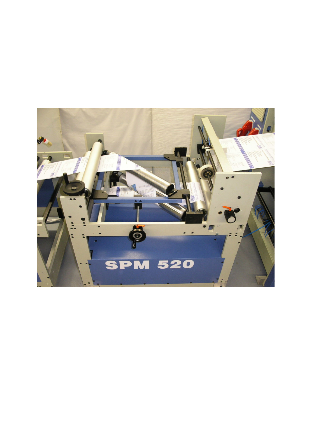
SPLIT & MERGE STATION – SPM 520
Page 2

1. Safety Instructions
1.1 General Safety Instructions..........................................................….................3
1.2 Safety Officer................................................................................….................6
1.3 Electrical connection....................................................................…..................6
2. Technical Specifications
2.1 Specification....................................................................................................7
2.2 Connections / Dimensions...............................................................................7
3. General Description...............................................................….........8
4. Installation...........................................................................................8
5. S
tart-up
5.1 Initial switching on............................................................................................9
5.2 Schematic design of Split & Merge Station .................................…..............10
5.3 Replacement part list of Split & Merge Station...............................................11
5.4 Thread paper web .......................................................................…..............12
6. Servicing
6.1 Lubrication Drawing.......................................................................................13
7. Fault Repair .....................................................................…..............14
As at: May ´05 Editor: MS.
2
Page 3

1. Safety Instructions
1.1 General Safety Instructions
• The S
of delivery and is essentially fail-safe.
• Risks to people, the split & merge station itself and other material assets of the
operator, stem from the Split & Merge Station, if:
- non-qualified employees work on and with the Split & Merge Station.
- the Split & Merge Station is used incorrectly.
• The Split & Merge Station must be projected in such a way that it fulfils its function
in faultless operation and causes no personal risk during normal set-up and
conventional use. This also applies to its co-action with entire system.
• Only operate the split & merge station in sound condition.
• During operation with the split & merge station be careful not to get hands or
loose clothing caught in the moving parts. Always keep the machine casing shut.
• Retrofitting, modifications or alterations to the Split & Merge Station are strictly
forbidden. You must first consult MBO.
• Use the appropriate safety measures to prevent personal or property damage in
the event of the split & merge station breaking down.
• Wear appropriate protective clothing and footwear when working on or with the
machine.
• The applicable accident prevention regulations as well as other generally
recognised safety and occupational medicine regulations shall be adhered to.
• It is always imperative to obey all safety instructions. Observation of which
ensures your safety.
• Refrain from any mode of operation, which:
¾ endangers the life and limb of the user or a third party.
¾ brings about impairments in the machine or other material assets.
¾ disregards the safety instructions specified.
• Maintenance and repair works must only be carried out by persons who are
familiar and informed on the risks, as well as possess the necessary skills.
plit & Merge system corresponds to the existing state-of-the-art at the time
3
Page 4

• Warning – personal danger!
¾ Increased risk with safety installations switched off. Basically do not disassemble
or switch off safety installations.
¾ Check for correct functioning of the safety installations on a daily basis.
¾ Report faults and defective safety installations to the manufacturer immediately.
¾ Keep casing closed during operation and only open once the malfunction is
eliminated.
¾ Only carry out repair on the compressed air supply lines and their components in
a depressurised condition.
¾ In using chemicals please observe the relevant safety data sheets and notes for
disposal, supplied by the respective manufacturer. Also take into consideration
the local safety requirements.
¾ Press the “emergency switch inside the line” for maintenance and repair works.
Also, the machine must be “switched off”.
¾ Close off the “danger zone” accordingly for maintenance and repair works (by
means of the appropriate danger notices and warning notes).
¾ Stop the “system (line)” and press the “emergency switch inside the line” before
you reach into the machine. This will avoid any possible danger to life and limb.
¾ In “threading” the paper, observe the safety instructions, as there is a particularly
high risk of injury from the slitter motor, guide rollers, spindles, antistatic unit etc.
for the operator.
Warning:
• An element of risk also remains for man and machine, if the Split & Merge Station
is installed incorrectly or not operated as intended. Bec
performs “rotating, pivoting as well as mechanical and electrical” work!
• Also, by adhering to the functionality described in this instruction manual, there
remains an element of risk by e.g. ripping the paper web during production. The
operator could be injured by e.g. the rotating splitter motor, the powered antistatic
unit etc. Should the paper web tear, the machine (line) must be stopped
immediately, by pressing the switch "STOP (16) on MBO sheeter” or the “set
up switch (1) on the MBO unwind”. Furthermore, it is recommended that
you press the emergency switch in the event of “malfunction”.
• There is an element risk for the operator if the machine is handled incorrectly, e.g.
turning of the "pneumatic draw rollers", the side and height registering, splitter etc.
There is a danger of the operator being cut or crushed/trapped. You therefore
operate the machine, as described under point 6.1.
• If it is necessary to disassemble safety installations for set-up, repair and
maintenance work, then all installations are to be refitted afterwards.
• The machine may not be operated in areas where there is risk of explosion, such
as e.g. explosive dust. Any usage beyond this is not regarded as conventional.
The manufacturer takes no responsibility for any resulting damages. The
user/operator bears the risk alone.
• No liability will be assumed for damages and machine breakdown, which results
from:
¾ Disregard of instruction manual
¾ Machine modifications on one's authority.
¾ Handling faults.
¾ Improper work on and with the equipment
¾ Use of inadequately skilled employees.
ause the machine
4
Page 5

¾ Use of incorrect replacement parts. If you use non-approved replacement parts
the function is not guaranteed. Only use replacement parts approved by the
manufacturer!
• The operator has to instruct the operating personnel on the possible risk of
explosion when handling inflammable liquids, in accordance with explosion
guidelines.
¾ Only use cleaning agent and solvent with a flashpoint of at least 55°C.
¾ Aggressive chemicals can damage components.
¾ Do not heat over flashpoint.
¾ Provide good room ventilation.
¾ No naked flame, no ignition sources.
¾ Immediately eliminate any matter emitted correctly.
Warning: Use protective equipment and follow safety data sheets!
• Safety notes on transportation:
¾ Caution – damage to components!
¾ Damage caused by improper transportation
¾ On acceptance of the machine pay attention to packaging damage and report this
immediately to the manufacturer.
• Safety note on maintenance:
¾ Only carry out authorised maintenance work.
¾ Maintenance work should only be carried out by a trained employee who is
familiar with and has been briefed on the dangers as well as having the necessary
skills.
¾ Prior to start-up, all safety conditions must be satisfied.
¾ Caution – live voltage. Inobservance can result in an electric shock. Warning
danger to life!
Please observe the following points for maintenance and repair works on the
electrical system:
9 Switch machine to voltage-free.
9 Safeguard against resetting.
9 Determine voltage freedom.
9 Ground and short-circuit.
9 Cover adjacent live parts.
¾ Caution – Risk of damage from electric and electronic components!
5
Page 6

1.2 Safety officer
• Operator is any natural or legal person, who uses the Split & Merge Station or on
whose instructions the Split & Merge Station is used.
• The operator or his safety officer must guarantee that
- all relevant regulations, references and laws are adhered to.
- only qualified employees work on and with the Split & Merge Station.
- the operator is notified on the various risks and dangers, which emanate from
the Split & Merge Station for man and machine.
Qualified employees are persons who are authorised by the safety officer, based on
their training, experience, instruction and knowledge on relevant standards and
provisions, accident prevention regulations and operating conditions, to carry out the
required operations and be able to identify and prevent potential dangers. (Definition
for skilled personnel according to IEC 364).
1.3 Electrical connection
• The installation and repair works must only be c
• The applicable national accident prevention regulations shall be observed for
work on live parts.
• The electrical installation shall be carried out in accordance with the pertinent
regulations (e.g. line cross section, safeguarding, ground wire connection etc.)
Furthermore, notes are available in the Split & Merge documentation.
• In connection with another module e.g. MBO sheeter or unwind is connected via
four multipoint connectors.
( Cekon 16A for power supply (compressor) and one 5pol. Control plug for the 24
VDC supply for the antistatic unit).
The splitter motor is connected via two separate plugs to the unwind or cross
cutter.
• The electric motors used are arranged on the right rotating field in the split &
merge station.
• It is imperative to observe the safety instructions described in chapter 1!
Attention Danger:
¾ Personal safety: Check whether all terminals are voltage-free before working on
the machine.
¾ Disregarding of the safety instructions: there is the threat of death of serious
injury.
¾ Caution: property damage: Incorrect handling of the machine can cause
damage to the machine and its surrounding area.
arried out by a specialist.
6
Page 7

2. Technical specifications
2.1 Specifications
• Production speed max. 250m/min
• Web width min. 150mm
• Web width max. 520mm (larger as option)
• Means of overlap min. 0mm
• Means of overlap max. 300mm
• Paper quality 36gr/m² - 200gr/m²
• Slit registering +/- 5mm
2.2 Connections / Dimensions
• Electrical connection 3 x 16A, 380V,50Hz,N,PE,
• 24VDC for antistatic unit (optional)
• Compressed air line (PK 4-hose with quick release dev
lubricated.
• L x B x H = 1.2m x 1.3m x 1.2m
• Weight 450 kg
• Ambient temperature: 5-35°C
• Continuous sound pressure level: 78dB (A) (at 40m/min speed with an MBO
sheeter and unwind).
ice) 6bar dehumidified and
7
Page 8

3. General Description
The Split & Merge Station (SPM) is designed for the super
under web tension. A web duplication is possible on one side of printed or
personalised webs at top speeds. The Split & Merge Station is modularly built and
can be integrated smoothly into the existing system (line). On entry to the Split &
Merge Station there is a "pneumatic pinch roller“, which turns the paper by means of
a switch on the guide roller. The guide roller itself is fitted with an override (freewheel) clutch, which prevents the paper web from drawing back into unwind.
The superimposition (longitudinal & transverse registering) is made manually over the
respective setting spindle. A 0-300mm overlap method materialises. Both forms of
production can be processed with the Split & Merge Station (Pin Less or Pin Feed).
The side registering of the slitter unit (LCUM) is set mechanically via a thumb wheel
and totals +/- 5mm. Furthermore, a blade is integrated for the centre cut. Other
blades (LCUM) are available for e.g. edge trim as an option. The guide roller of the
Split & Merge Station is air-cushion supported, which is created by an integrated
compressor. The processing of the superimposed paper web e.g. with an MBO
sheeter with „chip-out“, necessitates static fixing. This antistatic unit is
supplied as an option.
imposition of two webs
4. Installation
In the assembly/disassembly of the Split & Merge Station the trained personnel
should ensure that the machine is arranged horizontally in machine and transverse
direction. Also, the Split & Merge Station must be in direct alignment to the existing
system, because, otherwise this will jeopardise a direct run of the paper web. In
addition, qualified personnel should ensure that sufficient room (e.g. the accessibility
of switch cabinets) is given for maintenance work. From the machine frame to the
ground approximately the same distance should be set over the set-up feet as for the
pre-machine (MBO unwind). The reason for this is that the entire system (line) is
aligned at the same height. To unwind there should be a distance of around
30-50cm and to the sheeter 80-110cm. After complete alignment of the Split &
Merge Station the counter nut of the set-up feet should be tightened.
Please follow the safety precautions when performing these operations! (see chapter
1 safety instructions).
The functioning of the Split & Merge Station is checked at the factory and it is packed
professionally. The packaging material shall be disposed, or reused, in accordance
with the applicable terms. You can remove the Split & Merge Station from the
packaging (pallet) with an appropriate lifting column (e.g. forklift truck). Here you
should ensure that no cable etc. is between the fork and frame. Furthermore, it is
mentioned that the centre of gravity of the split & merge station is on the driving side.
This instruction manual is an integral part of delivery. For detailed commissioning of
the antistatic unit we refer to the separate operating instructions.
8
Page 9

5. Start-up
5.1 Initial switching on
• The installation and repair works must only be carried out by a specialist.
• Pr
ior to switching on the split & merge station for the first time check the wiring for
completeness, short-circuit and earth connection.
• Line connector: Connect the supply line directly to the unwind via the designated
Cecon plug.
• Control wire: See documentation or alternatively, via a 5pol. Control plug.
• Connect the slit motor to the MBO unwind via the two plugs.
• Ensure right rotating field.
• Connect the compressed air line (6bar) directly to the existing system (line) or a
suitable compressor.
• Make sure that all enclosures and coverings are shut.
• See that the machine is aligned.
• Please pay attention to all safety precautions.
• Should damages become visible, the Split & Merge Station must not be operated.
9
Page 10

5.2 Schematic Design of Split & Merge Station
5.2 Schematic Design of Split & Merge Station
Comment: Please obtain article description (order number) from the table in fig.5.3.
10
Page 11

5.3 Replacement list of Split & Merge Station
Fig.5.3 Replacement list of Split & Merge Station
e.g. the toggle, 28 in the picture, has the order number GN-323-100-K10-D
11
Page 12

5.4 Threading paper web
Fig. 5.4.1 Entry to Split & Merge Station
Fig.5.4.2 Entry and centre piece of Split & Merge Station
12
Page 13

Fig.5.4.3 Overall picture of paper web
• Split the paper web by hand using the slitter.
• Guide the paper from the top guide roller directly to the lowest guide roller. Here
you separate the paper web guide into two parts. See fig.5.4.1
• The back part is brought from the bottom guide roller at the point of entry directly
to the bottom guide roller at the exit. Then loop the centre guide roller at the exit
as in fig.5.4.3.
• The back part is brought from the bottom guide roller at the point of entry directly
to the centre guide roller at the exit. Afterwards you thread the paper web
between both with approx. 45° arranged guide rollers, and by doing so the lower
of the two is supported with air. See fig.5.4.2. Then you guide the paper web over
the centre guide roller to the exit.
6. Servicing
6.1 Lubrication drawing
Warning: Risk of injury by: „ e.g. cogwheel connection, screws on knurls and
worm gear, guide rollers, crossbars, pin rollers, slitters, compressor,
longitudinal and transverse registering, antistatic unit, as well as drive motors.
Comment: Servicing intervals apply for single-shift operation.
♦ Lubricate c ogwheel connections once every 4 weeks e.g. . L71V of FAG or DIN
51502 K3N-30.
13
Page 14

♦ Grease lubricating nipple on cutter unit once every 4 weeks with grease gun
(lubricant: DIN 51502 K3N-30).
♦ Screws and worm gear and spindles should als o be bathed every 4 weeks with
the above-mentioned lubricant.
7. Fault repair
Fault
Slitter motor, compressor is
not working.
Slitter motor is not working
Pin roller
is not reacting.
Antistatic unit is not working.
Paper web is running
unevenly.
Cause
No voltage available
Emergency off-switch active.
Curved tooth coupling not in
position.
System (line) not ready.
No air pressure available.
No 24VDC available.
SPM is not aligned correctly.
Web edge guide control in
incorrect operating mode.
Paper roll is not aligned.
Longitudinal and transverse
registering not set.
Remedy
Connect the main and control line.
Reset the emergency circuit.
Check the curved tooth coupling for
passability and tighten the grub screw.
Switch the system completely “OFF”
(approx. 20 sec.) and “ON” again.
Switch the system to automatic mode.
Connect the compressed air line via
the PK-4 hose.
Consult MBO as a
matter of urgency.
Align SPM as described in chapter 4.
Switch the web edge guide control into
automatic operation.
Bring the paper roll into direct
alignment to the existing system.
Adjust the registering again using the
knurls. Check the angle of the guide
roller aligned at approx. 45° and correct
the angle.
Slitter motor is not cutting
correctly.
Incorrect setting.
14
Bring the blade into position using an
Allen key so that there is slight
pressure on the fixed blade.
Check the half shell coupling, and if
required turn this by opening the Allen
key.
Check the rotating axis and ballbearing of the blade.
 Loading...