

Page 1

Operating ManualOperating Manual
Operating Manual
Operating ManualOperating Manual
SBAP 46/72/82 MESBAP 46/72/82 ME
SBAP 46/72/82 ME
SBAP 46/72/82 MESBAP 46/72/82 ME
VV
ertical Stacker Deliveryertical Stacker Delivery
V
ertical Stacker Delivery
VV
ertical Stacker Deliveryertical Stacker Delivery
with pressingwith pressing
with pressing
with pressingwith pressing
and marking deviceand marking device
and marking device
and marking deviceand marking device
Page 2

Operating Manual
SBAP 46/72/82-ME USA
Contents
Prologue ................................................................................................................. 4
1.0 Machine specification ............................................................................................ 4
1.1 Manufacturer .......................................................................................................... 4
1.2 Type:........................................................................................................................4
1.3 Technical data ........................................................................................................ 5
1.3.1 Sizes .................................................................................................................................................. 5
1.3.2 Floor plan: ......................................................................................................................................... 5
1.4 Documentation ....................................................................................................... 6
1.5 User information / Functioning description ......................................................... 7
2.0 BASIC SAFETY INSTRUCTIONS .......................................................................... 8
2.1 Warnings and symbols .......................................................................................... 8
2.2 Safety in the working place Destined use of the Vertical Stacker Delivery........ 8
2.3 Safety devices ...................................................................................................... 10
2.3.1 Protective hoods – Layout .............................................................................................................. 10
2.3.2 Protective hoods – Checklist .......................................................................................................... 10
2.3.3 Check list: warning labels (oder warning signs) ........................................................................... 11
3.0 Transportation, installation, and initial operation............................................... 15
3.1 Transportation ...................................................................................................... 15
3.2 Installation ............................................................................................................ 15
3.3 Erection ................................................................................................................. 16
3.4 Electrical connection ........................................................................................... 17
4.0 Service / Maintenance .......................................................................................... 18
4.1 Procurement of spare parts ................................................................................ 18
Alterations reserved
Stand 10/2006Page 2
Page 3

Operating Manual
SBAP 46/72/82-ME USA
4.2 Lubrication / Cleaning .......................................................................................... 19
4.3 Cleaning of transport tapes and pressing rollers .............................................. 20
4.4 Tensioning of tapes, belts and chains ................................................................ 21
4.4.1 Chains at main drive motor ............................................................................................................ 21
4.4.2 Drive chains for the transport tape at the collector table .............................................................. 22
4.4.3 Drive of pressing rollers and infeed tapes .................................................................................... 23
4.4.4 Transport tape at the collector table .............................................................................................. 24
4.4.5 Lower line-up tapes ........................................................................................................................ 24
4.4.6 Upper line-up tapes......................................................................................................................... 25
4.4.7 Pile transport tapes......................................................................................................................... 25
5.0 Operation (of the delivery) ................................................................................... 26
5.1 Control desk ......................................................................................................... 26
5.2 Infeed table ........................................................................................................... 27
5.2.1 Infeed tapes ..................................................................................................................................... 27
5.2.2 Multiple-up production ................................................................................................................... 28
5 2.3 Marking device ................................................................................................................................29
5.3 Pressing unit ........................................................................................................ 30
5.4 Collector table ...................................................................................................... 31
5.5 Line-up tapes and line-up table .......................................................................... 32
6.0 Putting out of service ........................................................................................... 34
6.1 Details of storage ................................................................................................. 34
6.2 Environmental waste disposal ............................................................................ 35
6.2.1 Disposal of the waste machine ...................................................................................................... 35
6.2.2 Disposal by instructing the supplier .............................................................................................. 35
6.2.3 Disposal by a disposal and demolition company ......................................................................... 35
6.2.4 Disposal by your own company ....................................................................................................35
6.2.5 Ground water preservation ............................................................................................................. 36
6.3 Final remarks ........................................................................................................ 36
Page 3Alterations reserved
Stand 10/2006
Page 4

Prologue
The MBO Vertical Stacker Delivery SBAP 46/72/82 - ME you have purchased is a valuable
piece of equipment. It is absolutely imperative that you comply with all Safety Regulations
and Safety Instructions. This Operating Manual is designed to instruct you to correctly operate
the machine, to comply with the Safety Regulations, and also to maintain the machine
properly.
1.0 Machine specification
Operating Manual
SBAP 46/72/82-ME USA
1.1 Manufacturer
MBO Binder & Co. Maschinenbau Oppenweiler
Grabenstrasse 4, D-71570 Oppenweiler, Germany
P.O. Box 1169, D-71567 Oppenweiler, Germany
Tel. +49 7191 460
Fax +49 7191 4634
1.2 Type:
Vertical Stacker Delivery SBAP 46/72/82 - ME
Alterations reserved
Stand 10/2006Page 4
Page 5

Operating Manual
SBAP 46/72/82-ME USA
1.3 Technical data
1.3.1 Sizes
SBAP 46-ME SBAP 72-ME SBAP 82-ME
Working width: 17 3/4“ 28 3/8“ 32 1/2
Maximum infeed height: 37 3/8“ 37 3/8“ 37 3/8“
Minimum infeed height: 15“ 15“ 15“
Sheet width / line-up height max.: 11 3/4“ 11 3/4“ 11 3/4“
Sheet width / / line-up height min.: 3 1/8“ 3 1/8“ 3 1/8“
Length of pile: 28 3/4“ 28 3/4“ 28 3/4“
Pressing power max.: 2000 kp 2000 kp 2000 kp
Speed: 40-155m/min 40-155m/min 40-155m/min
Power requirements: 1.3 kw 1.3 kw 1.3 kw
1.3.2 Floor plan:
The permitted working area during the operation is marked in grey.
(measure in inch)
Page 5Alterations reserved
Stand 10/2006
Page 6

Operating Manual
SBAP 46/72/82-ME USA
1.4 Documentation
Customer:
Machine configuration: Vertical Stacker Delivery SBAP 46/72/82 - ME
Machine No.:
Serial No.:
BA Batch Counter IVO:
Electrical data:
Wiring diagram no.:
Operational voltage V3/Hz:
Control voltage V/A:
Control voltage V/A:
Total nominal current A:
Fuse at power supply A:
Wiring diagram no’s.:
Test mark GS Nr.:
Test mark CE Nr.:
Certificate of Conformity:
Perceived noise level (dB/AI):
GS marking no.:
Alterations reserved
Stand 10/2006Page 6
Page 7

Operating Manual
1.5 User information / Functioning description
The Vertical Stacker Delivery SBAP 46/72/82 - ME is a mobile, separate unit with self-drive to
vertically set up signatures with the spine downwards. The sheets are simultaneously pressed
and the batches may be counted through a batch counter and displaced to each other.
For multiple-up productions the different ups may be separated at the entry of the vertical
stacker delivery by slanting the round belts.
SBAP 46/72/82-ME USA
Page 7Alterations reserved
Stand 10/2006
Page 8

Operating Manual
2.0 BASIC SAFETY INSTRUCTIONS
2.1 Warnings and symbols
The following designations or symbols are used for very special instructions in this Operating
Manual:
>NOTICE< Special instructions in respect to the economical use of the machine.
>ATTENTION< Special instructions or requirements and prohibitions to avoid injuries and damage.
>DANGER< Instructions or requirements and prohibitions to prevent personal injuries or extensive
damage.
Only skilled and instructed qualified personnel is allowed to operate the machine.
The operator must be at least 18 years old
SBAP 46/72/82-ME USA
2.2 Safety in the working place Destined use of the Vertical Stacker Delivery
2.2.1 MBO units correspond to their prescribed Safety Technical Requirement at the time of their shipment.
For this purpose, any moveable and rotating parts are covered with protective hoods and
are mechanically or electrically interlocked to such an extent as to not unreasonably detract from
the operation.
- Single person operation only (insufficient view at the drive side).
2.2.2 With technical safety precautions it is extremely important that all operating personnel receive
sufficient technical safety instructions and are advised of all potential sources of danger. However,
it must be remembered that even with proper use of the machine, accidents can occur which
present a danger to life and limb of the operator or third parties. Respectively, it does not exclude
the detraction of the machine and other material assets.
2.2.3 The delivery should only be operated when in good working order. Any malfunctions that may
impair safety must be removed immediately by trained personnel of the manufacturer/supplier.
2.2.4 The delivery is exclusively designed to handle folded paper sheets. The processing of any other
materials should not be attempted as the manufacturer or supplier will not be liable for any resulting
damage.
2.2.5 Carefully read the complete Operating Manual, including the Safety and Service Requirements,
before you operate the machine.
2.2.6 The Operating Manual should be kept with the machine at all times.
2.2.7 Complete the Operating Manual, if necessary with internal Safety Instructions, as well as with
the legal regulations for the Prevention of Accidents.
Alterations reserved
Stand 10/2006Page 8
Page 9

Operating Manual
2.2.8 Make sure that all frequently substituted operators are thoroughly informed about the aforementioned
subjects and trained accordingly.
2.2.9 Never remove any protective or safety devices from the delivery, and do not make any changes
that may impair the safety of the delivery.
2.2.10 Never use any tools which are not in perfect condition, and make sure that no tools are left on the
delivery after completion of settings and maintenance work. Tools that fall into the delivery may
cause serious injuries and damage.
2.2.11 Note that all Safety Instructions are kept in a legible and visible condition.
2.2.12 Any audible and visible change on the delivery in relation to its safety must be reported
immediately to the supervisor or manager of your company.
2.2.13 All operating personnel should be aware that loose clothing, jewellery or long hair can cause serious
injuries if caught in the delivery.
2.2.14 It is absolutely prohibited to clean the transport tapes or pressing rollers, eliminate malfunctions,
or to undertake adjustments while the delivery is in operation.
>DANGER< Therefore, always activate the EMERGENCY STOP button.
SBAP 46/72/82-ME USA
2.2.15 Make sure that no other person starts the delivery while you are working on it, e.g. adjustment or
other works!
>DANGER< Therefore, always activate the EMERGENCY STOP button, or turn OFF the main
switch, or unplug the delivery.
2.2.16 Do not immediately turn the delivery ON if it has stopped for any inexplicable reason. Make sure
that the delivery is in good working condition and that no other person is working on the delivery.
2.2.17 Turn off the main switch and secure it, if necessary, with a lock if you are required to undertake
extensive mechanical or electrical maintenance and repair work.
2.2.18 Never open the main or subcontrol panel! Only authorised personnel should gain access to electronic
control cabinets as there are no user serviceable parts.
>DANGER< if control cabinet is open! All main terminals could be alive even though the
mains switch has been turned off.
2.2.19 Any damaged cables or electrical connections must be reported to the appropriate supervisor
of your company.
2.2.20 Machine connections must be installed in such a manner that no cables, tubes or hoses are left
trailing.
Page 9Alterations reserved
Stand 10/2006
Page 10
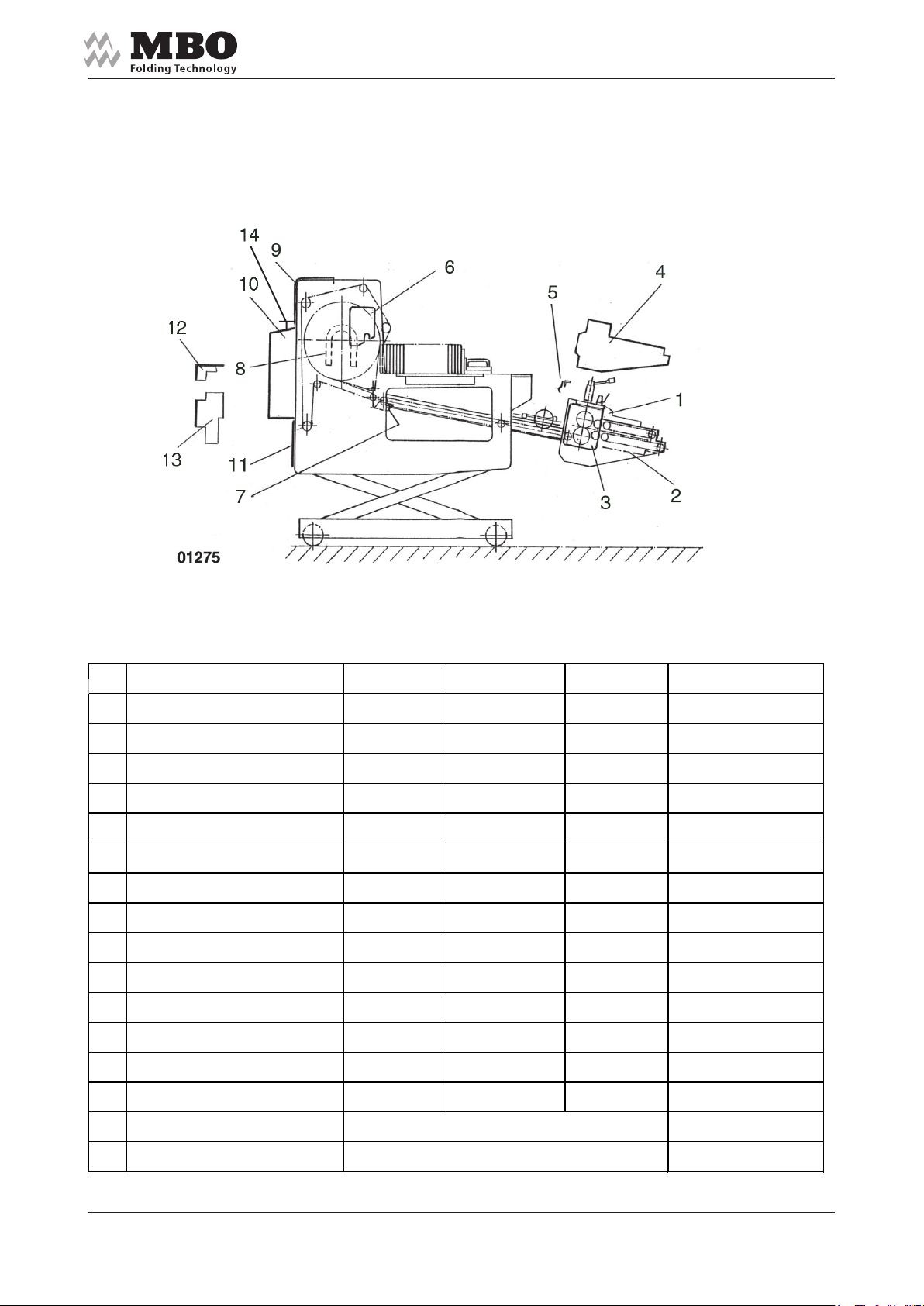
2.3 Safety devices
2.3.1 Protective hoods – Layout
Operating Manual
SBAP 46/72/82-ME USA
2.3.2 Protective hoods – Checklist
Pos De signation Function Visible control Result Rem ark
Guard at infeed
1
Cover infeed
2
below
Guard above
3
gear wheel
Protection hood at
4
drive
Guard for touching
5
Guard over
6
adjus ting chain
Guard over
7
belt drive s ystem
Guard over
8
drum drive
U p p er c o ve r
9
Electric box and
10
m iddle c over
Cover below
11
Cover over
12
drive chain
Cover over
13
drive chain
EM E RG E NCY -STOP switch in the operator field
14
control
date nam e signature
Alterations reserved
Stand 10/2006Page 10
Page 11
Operating Manual
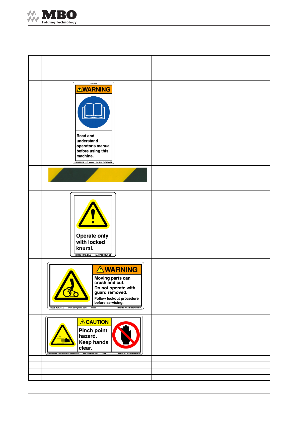
2.3.3 Check list: warning labels (oder warning signs)
SBAP 46/72/82-ME USA
Pos. Warnings Introduction
At first commissioning
(oder at initial operation)
(first customer)
1
2
3
Note
4
5
Date:
Name:
Signature:
Page 11Alterations reserved
Stand 10/2006
Page 12
Operating Manual
Pos. 1
Significance:
Please read and understand
the operating manual before you
start to work on the machine.
SBAP 46/72/82-ME USA
Pos. 2
Significance:
Danger from infeed point.
Keep away your hands from the
rotating shaft!
Pos. 2
Significance:
Danger of squeezing!
Keep away your hands when the
transportation plate is moving.
Alterations reserved
Stand 10/2006Page 12
Page 13

Operating Manual
Pos. 3
Significance:
Work only with a tightened lever.
Danger of jerky height adjustment in
case of non-tightened lever.
SBAP 46/72/82-ME USA
Pos. 4
Significance:
Danger of dragging through transport
tape. Keep away your hands from infeed
points!
Pos. 4
Significance:
Danger of dragging through transport
tape. Keep away your hands from infeed
points!
Page 13Alterations reserved
Stand 10/2006
Page 14
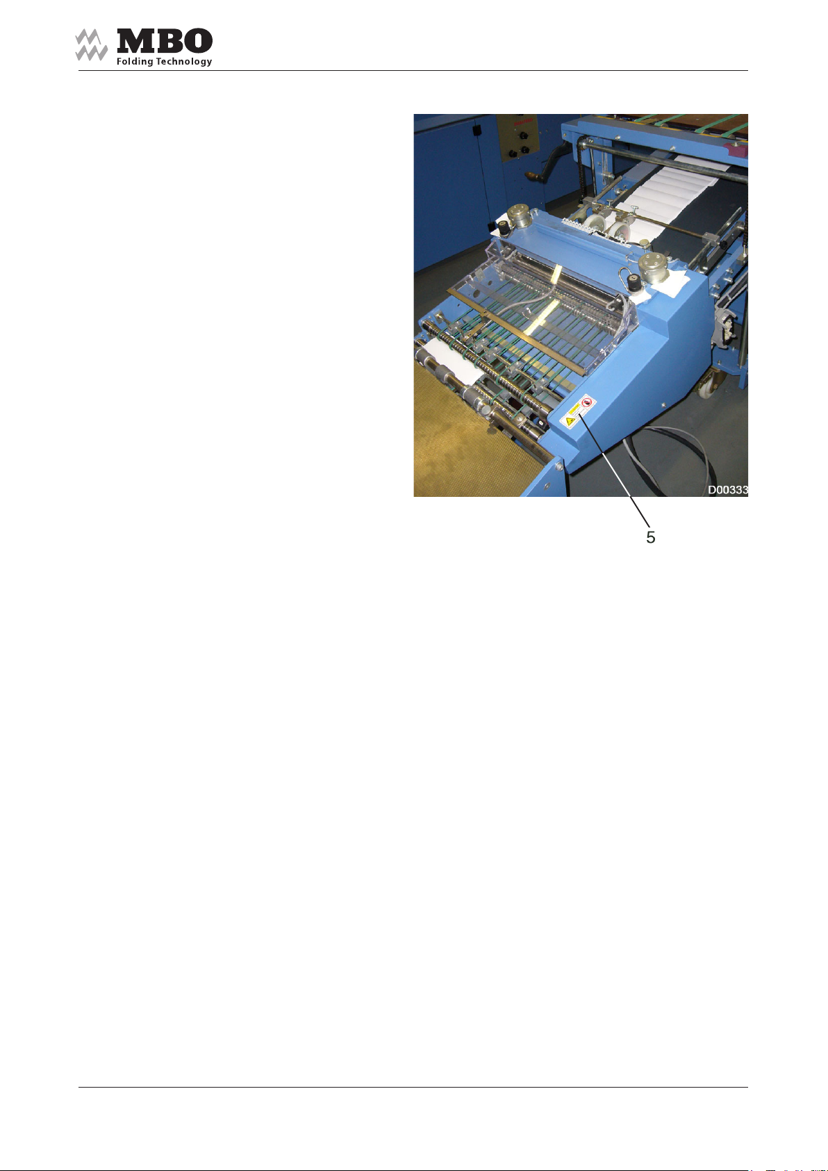
Pos. 5
Significance:
Non-observance may possibly
cause bruises to the hands.
Please keep your hands away
from this danger spot.
Operating Manual
SBAP 46/72/82-ME USA
Alterations reserved
Stand 10/2006Page 14
Page 15

Operating Manual
SBAP 46/72/82-ME USA
3.0 Transportation, installation, and initial operation
This part of the Operating Manual is specifically directed at service personnel and internal
authorised personnel responsible for transportation and installation.
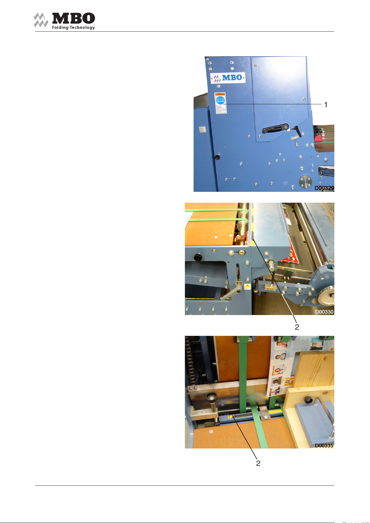
3.1 Transportation
The Vertical Stacker Delivery
SBAP 46/72/82 – ME is shipped on a
pallet or in a crate.
Carry the pallet as close as possible to
its final destination by means of a forklift.
Unscrew the delivery from the pallet.
Remove the delivery from the pallet
or crate by lifting with a forklift
(see markings 1 on the frame).
>ATTENTION< There is a danger of risk
of injuries as the delivery may overturn!
>DANGER< The delivery must be
supported by two persons.
The ideal operating temperature is 10-35 °C.
3.2 Installation
Clean the SBAP46/72/82 - ME with rust preventing agents.
Page 15Alterations reserved
Stand 10/2006
Page 16
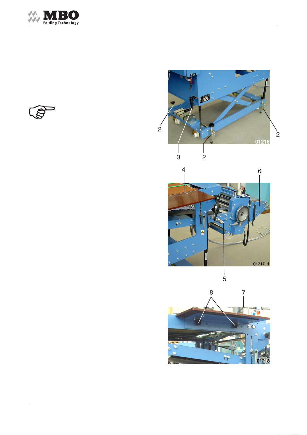
3.3 Erection
Position the SBAP 46/72/82 - ME
delivery next to the folding machine
and secure it with supporting screws 2
against displacement.
>NOTICE< The centre of the sheet
should be equal to the centre of the
delivery!
Position the line-up table 4 to
the suitable pick-up height by means
of the crank 3.
Operating Manual
SBAP 46/72/82-ME USA
The necessary height of the
infeed table 6 can be adjusted by means
of the crank 5.
This infeed height should match the
exit height of the folding machine.
Subsequently, fasten the knock-up
table 7 to the line-up table by
means of the knurled screws 8.
Alterations reserved
Stand 10/2006Page 16
Page 17
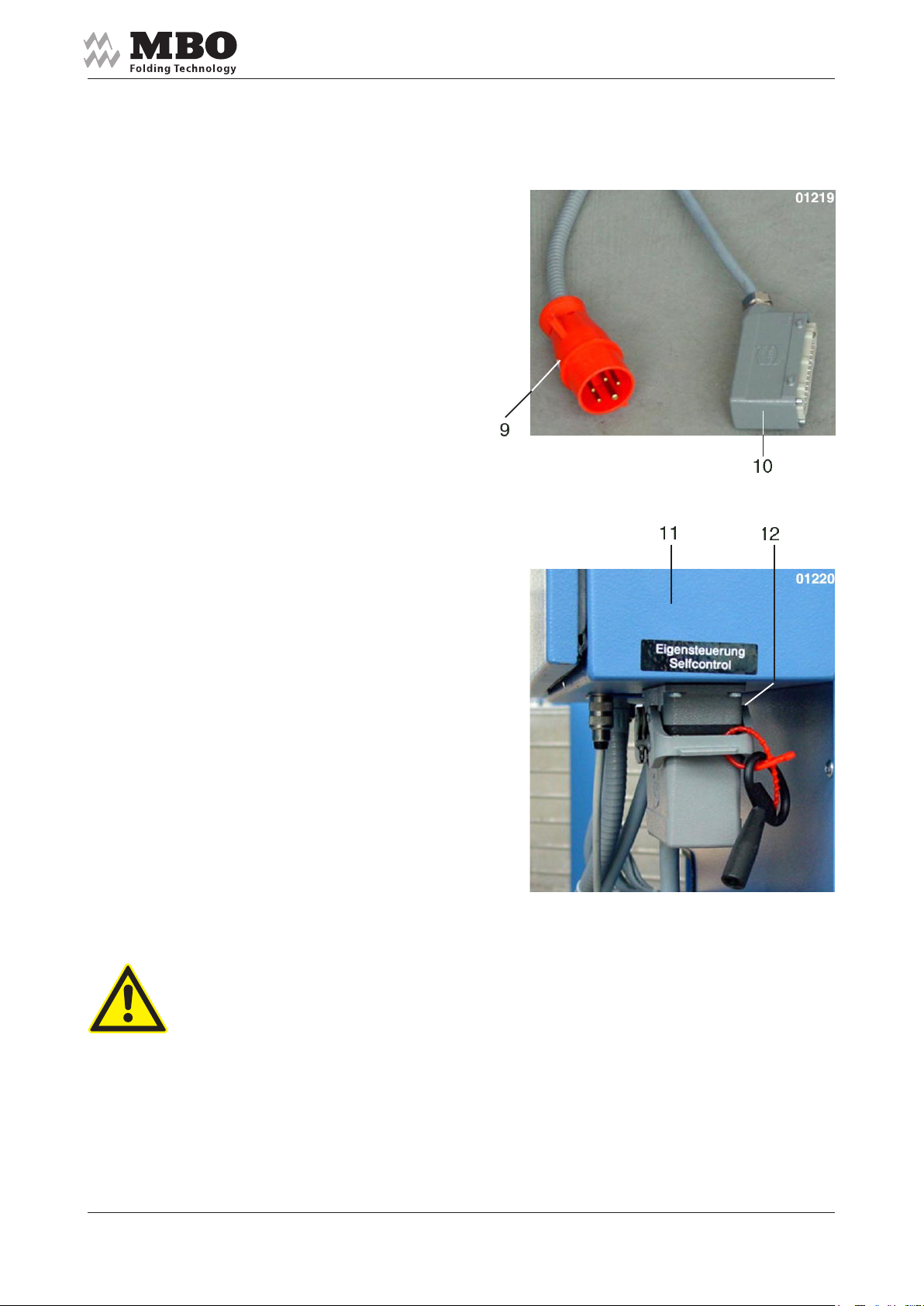
3.4 Electrical connection
Connect the SBAP 46/72/82 - ME to
the folding machine by means of
the power supply plug 9
and control plug 10.
Due to its self-control the
SBAP 46/72/82 - ME may also be
connected to foreign folding machines.
Operating Manual
SBAP 46/72/82-ME USA
For this purpose insert the power supply
plug into the supply circuit,
and the control plug into the socket
„Self-Control“ 12 at the control panel 11.
>DANGER< Please note that there is no joint OFF switch if the MBO Vertical Stacker Delivery is
connected to a foreign machine. We must expressly advise you that there is no safety cut-off if
the delivery is connected to a foreign machine. Both units must be turned ON and OFF separately!
The manufacturer shall not be liable for any damage or injuries caused by the lack of safety cut-off
devices!
Page 17Alterations reserved
Stand 10/2006
Page 18

Operating Manual
4.0 Service / Maintenance
This part of the Operating Manual is specifically directed at service personnel and internal
authorised personnel of the operating company responsible for service and maintenance.
>DANGER< Unless the delivery is isolated no service or maintenance work should be carried
out. Always activate the EMERGENCY STOP button or turn OFF the main switch and secure
it with a lock.
4.1 Procurement of spare parts
SBAP 46/72/82-ME USA
>ATTENTION< Only use spare parts that are supplied or recommended by the manufacturer.
For inquiries and spare parts orders it is necessary to provide the machine and serial number,
which may be obtained from the label 1.
Alterations reserved
Stand 10/2006Page 18
Page 19
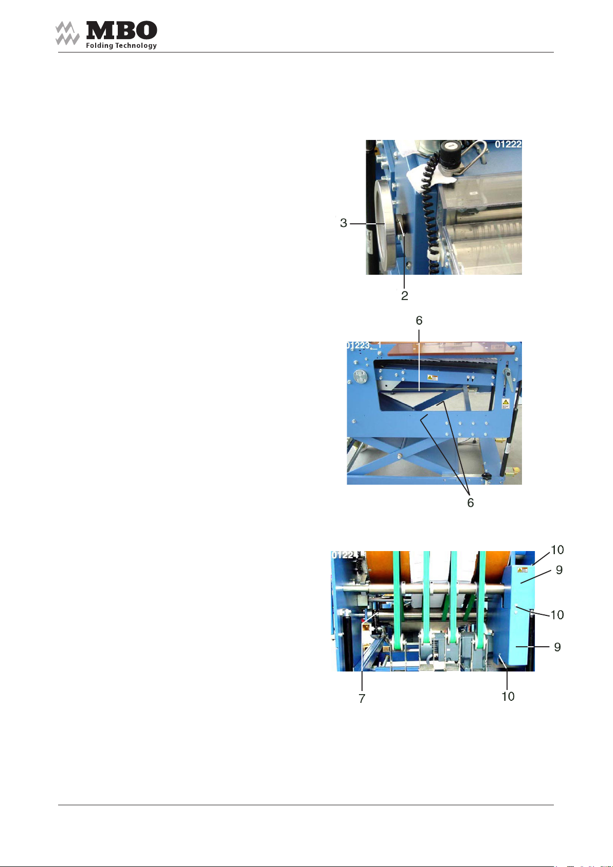
4.2 Lubrication / Cleaning
Clean and lubricate the lubricating
nipple 2 behind the hand wheel 3 with a
few drops of oil monthly.
Operating Manual
SBAP 46/72/82-ME USA
The threaded spindle 6 for the height
adjustments should be cleared of dust
and slightly greased monthly.
The drive chain 7 for the transport tape
should be cleaned and provided with a
slight touch of oil monthly.
All drive chains (see chapter 4.4.1)
going from the main motor should be
cleaned and provided with a slight touch
of oil monthly.
For this purpose, remove the protective
hood 9 that has been fastened with the
screws 10. Thereafter, replace the
protective hood and re-fasten all the
screws.
Page 19Alterations reserved
Stand 10/2006
Page 20

Operating Manual
SBAP 46/72/82-ME USA
4.3 Cleaning of transport tapes and pressing rollers
>NOTICE< Generally, the delivery must be cleaned after each application! Particularly moveable or
rotating parts that are frequently changed for exchange of sheet size must be cleared of dust.
Heavy dust may detract the function.
>DANGER< Transport belts and pressing rollers should be cleaned while the delivery has been
turned OFF. Activate the EMERGENCY OFF switch, or turn OFF the main switch, or pull out the
power supply plug.
>NOTICE< Depending on the extent of dirt, transport tapes and pressing rollers must be cleaned
occasionally. Heavy contamination of printing powder or deposit of ink on the transport tapes and
pressing rollers may cause reduction in the quality of the folded products. The tapes should be
cleaned with a cleansing agent suitable for synthetic materials. Please contact your machine/delivery
supplier for further details. Unsuitable cleansing agents may swell the material or devastate the
proportion of adhesive material.
>DANGER< Do not use any aggressive cleaners! Protective gloves should be worn while you are
cleaning. Protect exposed parts of the body against splashes or contact. Dispose the soiled cleaning
material in the correct manner, i.e. environmentally friendly. Consider the flammability of the cleansing
agent. In regard to disposal and skin irritability, please also remember that a residual danger could
eventually exist after a period of time. Check the technical data sheet of the cleansing agent
manufacturer.
>NOTICE< MBO, the manufacturer of this Vertical Stacker Delivery, recommends a cleaning
material made by VARN for the fold rollers, bearing the designation „VARN-Wash VM 111“ or „VWM“.
Our recommendation is on a label near the fold rollers.
VARN is a worldwide supplier to the printing industry. Therefore, it cannot be excluded that in
certain countries different designations are used. Please take the individual order number from
VARN’s technical data sheet.
>DANGER< Make sure to check all technical data of the manufacturers cleansing agents for any
0
possible residual danger in respect of disposal, flammability, and skin irritablility.
Alterations reserved
Stand 10/2006Page 20
Page 21
Operating Manual
4.4 Tensioning of tapes, belts and chains
>NOTICE< Check the tension of drive tapes and chains once a month and, if necessary,
re-tension.
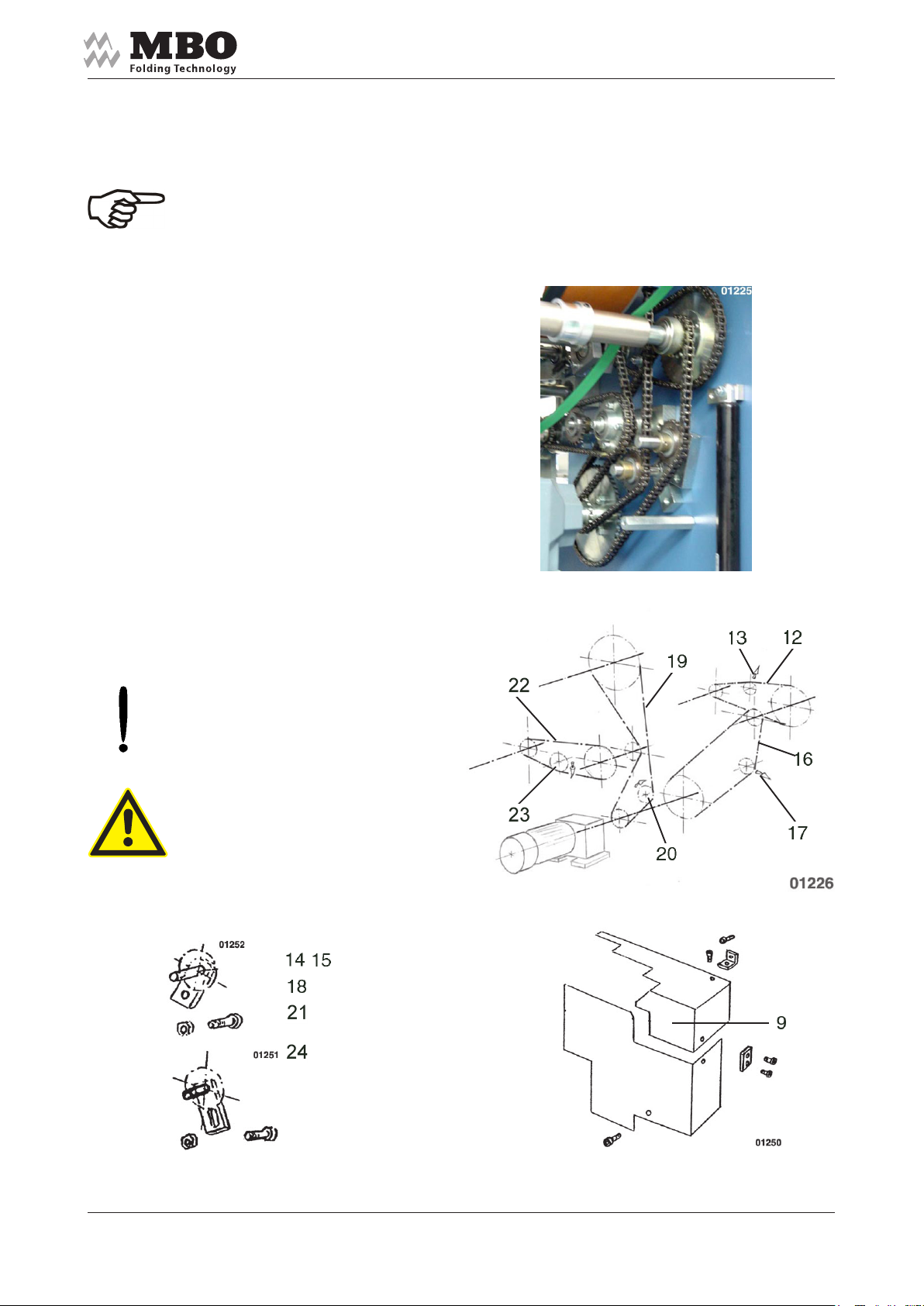
4.4.1 Chains at main drive motor
Remove the protective hood 9.
After loosening the screw 14 and
the nut 15 tension the chain 12 through
the chain tensioner 13.
After loosening the screw 18 tension
the chain 16 through the
chain tensioner 17.
After loosening the screw 21 tension
the chain 19 through the
chain tensioner 20.
SBAP 46/72/82-ME USA
After loosening the screw 24 tension
the chain 22 through the
chain tensioner 23.
>ATTENTION< Make sure that the
screws of chain tensioners are properly
re-tensioned after tensioning.
>DANGER< Make sure that no other
person is running the delivery while you
are working on it! Activate the
EMERGENCY STOP button,
or turn OFF the main switch,
or pull out the power supply plug!
Page 21Alterations reserved
Stand 10/2006
Page 22

Operating Manual
4.4.2 Drive chains for the transport tape at the collector table
The drive chain 29 for the
transport tape at the collector table 30
must be tensioned through the chain
tensioner 31.
For this purpose, remove the protective
hood 32 and loosen the screw 33 with
the externally located nut 34.
SBAP 46/72/82-ME USA
Subsequently, re-fasten the
screw with the nut and
replace the protective hood.
Alterations reserved
Stand 10/2006Page 22
Page 23

Operating Manual
4.4.3 Drive of pressing rollers and infeed tapes
Remove the protective hood over this
drive and loosen the Poly-V belt 35
through the belt tensioner 36 by
loosening the screw 37 with
the internally located nut 38.
The drive tape 39 should be
tensioned downward through the
tensioning roller 40.
SBAP 46/72/82-ME USA
For this purpose,
loosen the screw 41 with the
internally located nut 42.
After completion,
re-fasten the screws and
nuts and replace the protective hood.
Page 23Alterations reserved
Stand 10/2006
Page 24

Operating Manual
4.4.4 Transport tape at the collector table
The transport tape 43 at the collector
table may be tensioned on both sides.
For this purpose, loosen four screws 44
each on both sides and, upon loosening
the internally located nut 46,
unscrew the tensioning screw 45
counter-clockwise.
Make sure that the tape is equally
tensioned on both sides and does not
run off to the side.
Although the centre run is fixed laterally
through the disks 47, the tape should
not push too firm against the disks. After
you have completed the adjustments refasten all screws and nuts.
SBAP 46/72/82-ME USA
4.4.5 Lower line-up tapes
The lower line-up tapes 48 are
completely tensioned through the tape
shaft 49.
For this purpose, loosen the screws 50
and the counter nuts 51.
Consequently, the tape shaft is
tensioned by a constant clockwise turn
of both nuts 52.
After you have completed the tensioning
re-fasten all screws and nuts.
Alterations reserved
Stand 10/2006Page 24
Page 25

4.4.6 Upper line-up tapes
The upper line-up tapes 53 are
tensioned by weights 54.
For heavy, smooth paper sheets you
may hang up additional weights 55
which are delivered with the machine.
For this purpose, swing the control
cabinet 56 to the side, after you have
pulled the stop bolt 57 and removed the
guard plate 58.
>NOTICE< Do not use additional
weights when you process thin or
unstable paper sheets.
Operating Manual
SBAP 46/72/82-ME USA
After you have hung up the additional
weights, re-fasten the guard plate and
re-swing the control cabinet into its
previous position.
4.4.7 Pile transport tapes
The pile transport tapes 59 are
tensioned through the tape shaft 60.
For this purpose, loosen the screws 61
and the counter nut 62 on both sides.
Upon completion, re-fasten the screw
and counter nut.
Page 25Alterations reserved
Stand 10/2006
Page 26

Operating Manual
5.0 Operation (of the delivery)
5.1 Control desk
1 Key to „START“ the delivery.
2 Key to „STOP“ the delivery.
3 Red mushroom button on yellow background for „EMERGENCY STOP“.
4 Key for continuous sheet infeed.
5 Key for single sheet infeed.
6 Potentiometer for infinite speed regulation of the infeed tapes and pressing rollers.
7 Potentiometer for infinite speed regulation of the infeed tapes after the pressing rollers.
8 Selector switch to control the tapes after the pressing rollers:
a) Endurance run, e.g. to empty the delivery upon completion of a production run.
b) Photocell control during production; the tapes will stop if the sheet infeed has been
interrupted.
9 Batch counter „IVO“: only if the delivery is equipped with this option. See the attached Ope
rating Manual for functioning description. If no „IVO“ batch counter is provided, the „marking
device“ is controlled through the batch counter of the folding machine. Functioning description:
see the operating manual for the „folding machine“.
SBAP 46/72/82-ME USA
Alterations reserved
Stand 10/2006Page 26
Page 27

5.2 Infeed table
5.2.1 Infeed tapes
The products delivered from the folding
machine are taken by the round belts 1.
Positioning of tape rollers 2 and 3:
Loosen the screw 4 and displace the
guide 5.
The distance between the upper and
lower round belts may be adjusted for
product thickness by displacing the
upper tape rollers 8 and 2 and by
loosening the screws 7 at the collector
flange 7. Usually, this is only necessary
if you process very heavy products.
Remove the protective hood 6, loosen
the screws and nuts 7 and adjust the
tape rollers 2 or 8.
Make sure that they are adjusted
equally at both sides!
Operating Manual
SBAP 46/72/82-ME USA
Re-fasten the screws and nuts 7 and
replace the protective hood 6.
>DANGER< Before you perform these
actions it is absolutely imperative that
you activate the „EMERGENCY STOP“
or turn OFF the main switch of the
delivery. Otherwise risk of injury!
Page 27Alterations reserved
Stand 10/2006
Page 28

5.2.2 Multiple-up production
If signatures are cut into two- or threeup production in the folding machine:
Place the individual groups of round
belts 1, 2 and 3 diagonally to each other
or spread them!
Modify the position of the round belts 1,
2 and 3 only at the lateral side of the exit
of the infeed table – see item 5.2.1.
At least two round belts are necessary
for each production.
>DANGER< Before you perform these
actions it is absolutely imperative that
you activate the „EMERGENCY STOP“
or turn OFF the main switch of the
delivery.
Otherwise risk of injury!
Operating Manual
SBAP 46/72/82-ME USA
Two-up production
Three-up production
Alterations reserved
Stand 10/2006Page 28
Page 29

5 2.3 Marking device
>NOTICE< This device enables you to
exactly count and displace 1 batches to
each other in the desired number of
pieces to ensure the continuous take-off
of equally sized batches.
The desired number of pieces of
products of each batch must be entered
into the IVO – batch counter 9; see the
separately attached „IVO“ Operating
Manual.
If 9 does not exist, the marking device
will be controlled over the batch counter
of the folding machine. (see operating
manual „folding machine“)
Install a photocell 3 above the sheets.
Functioning check: The diode will light
up if a sheet is passing the photocell.
Operating Manual
SBAP 46/72/82-ME USA
As soon as the pre-selected number of
pieces of one batch is reached you
should displace the round belts to the
left or right side through the electromagnet 5 and marking bars 6.
Do not reach into rotating shafts!
>NOTICE< You should place the
photocell in such a way that it is not
influenced by the marking bars 6.
Page 29Alterations reserved
Stand 10/2006
Page 30

5.3 Pressing unit
How to adjust the pre-pressing rollers 1:
Insert a paper strip 2 into the calliper 3
(normally the full product thickness).
How to adjust the main
pressing rollers 4:
Insert a paper strip 5 into the calliper 6 -
(1/2 to 3/4 of the product thickness). For
opening turn the hooked key 7 left, and
for closing turn to the right (clockwise).
The micro switches 8 will turn the
complete delivery off if a product that is
too thick passes these micro switches.
>DANGER< Please be advised that
such switch-off will occur only if the
delivery is connected to an MBO
folding machine!
Operating Manual
SBAP 46/72/82-ME USA
Alterations reserved
Stand 10/2006Page 30
Page 31

5.4 Collector table
After the signature has passed the
pressing rollers the folded product will
fall onto the transport tape 1 of the
collector table 2.
The height of fall between the pressing
rollers and the collector table may be
adjusted at the adjustment grip 3 for
various products:
If you turn the adjustment grip
clockwise = you decrease the height of
fall; if you turn the adjustment grip
counter-clockwise = you increase the
height of fall.
>NOTICE< Unstable or thin products
require less height of fall; stable and
bulky products require more height of
fall.
Operating Manual
SBAP 46/72/82-ME USA
After the pressing rollers the sheet
passes the photocell 4. Functioning
check: The diode will light up if
a sheet is passing the photocell.
Thereby, it will set the
transport tape 1 into motion. The
collector rollers 6 should grasp the sheet
before the tape stops again after it has
left the photocell’s range of detection.
For positioning of the collector rollers it
is necessary to loosen both knurled
screws 7.
You may laterally displace the
collector rollers if you loosen the
knurled screws 8. The smoother bars 9
may be placed forward if you loosen the
knurled screw 10.
Wrinkled sheets after the pressing unit will cut off the delivery through the default switch 11.
The delivery will also be cut off if it is connected to an MBO folding machine. However,
if the delivery is connected to a foreign machine only the SBAP 46 - ME will cut off.
The second photocell and the second default switch will be used for two-up production.
The speed of the transport tape and therefore the adjustment of short or extensive
formation of shingles may be adjusted through the potentiometer at the control cabinet.
Page 31Alterations reserved
Stand 10/2006
Page 32

Operating Manual
5.5 Line-up tapes and line-up table
SBAP 46/72/82-ME USA
The shingled sheets are transferred by
the collector table 1 A between the
lower 1 and upper 2 line-up tapes and
transported by them around the drum 3
onto the collector table 4.
The speed of these line-up tapes
may be changed parallel to the
transport tape 1 A as they are driven
by the same motor. The height
adjustment of the line-up rollers 5 –
levelled to the upper edge of the folded
sheets 6 – may be performed through
the crank 7 after the clamping lever 8
has been loosened.
With short signatures, whose upper
edge 6 is deeper than the centre of the
drum 3, the pressure of the upper tape
onto the lower tape may be altered by
means of the line-up rollers:
Clockwise screwing of the red-marked
knurled nut 10 reduces pressure.
Counter-clockwise screwing of the redmarked knurled nut 10 increases
pressure.
A
Subsequently, you should secure the
position of the knurled screw by
countering the knurled nut 11.
The speed of the pile transport tapes 12
must be adapted to the production
speed and product thickness.
Low production speed and thin products
require less forward feed, but heavy
products and high production speed
require more forward feed.
continuation
Alterations reserved
Stand 10/2006Page 32
Page 33

Operating Manual
continuation
This forward feed can be adjusted
through the knurled screw 13:
Clockwise screwing of the knurled
screw 13 reduces forward feed.
Counter-clockwise screwing of the
knurled screw 13 increases forward
feed.
A retaining angle 14 is used to avoid the
tilt of the pile on the line-up table.
After loosening the knurled screw 16
the attachment plate 15 may be turned
or removed for various heights of
signatures.
Two retaining angles are used if you
process two-up productions.
SBAP 46/72/82-ME USA
The transport tapes 1, 2 and 12 should
only be displaced laterally in exceptional
cases.
At first, you should attempt to vary the
infeed position of the sheets into the
delivery by changing the position of the
delivery or by slanting the infeed tapes.
If you displace the transport tapes you
should ensure that all tape rollers for
each single transport tape are equally
displaced. We recommend using a tape
rule and measure from the delivery’s
side panel. Locking screws are fixed in
all tape rollers.
The lower transport tapes 1 are
displaced through the tape rollers 17
The upper transport tapes 2 are
displaced through the tape rollers 13,
and the pile transport tapes are
displaced through the tape rollers 19.
>ATTENTION< Make sure that these
tapes do not rub laterally as they may be
destroyed.
Page 33Alterations reserved
Stand 10/2006
Page 34

6.0 Putting out of service
6.1 Details of storage
• Check the premises in respect of temperature and humidity. The ideal storing temperature
rests between +15°C and +28°C. The higher the humidity the greater the danger of corrosion.
• It is essential that you take the weight details of the machine into con-sideration in respect of
the maximum load capacities.
• It is essential that you take the size details of the machine into consid-eration in respect of
the maximum load capacities.
• Prepare the gears/transmission for storage. You should also take into consideration that the
pre-requisites vary from case to case. Therefore, please contact the supplier of the
gears/ transmission and motor and fol-low the respective manual.
Operating Manual
SBAP 46/72/82-ME USA
• Clean dirt and dust carefully from the machine; do not use water - dan-ger of corrosion.
• Ensure that only an electrician disconnects the machine from the power supply.
• Use a fork lift to transport the machine.
• Cover the machine with foil.
Alterations reserved
Stand 10/2006Page 34
Page 35

Operating Manual
6.2 Environmental waste disposal
Dispose of single machine parts and all occurring waste materials from the K 800.2 Combi folding
machine environmentally according to:
For European . 75/442 EEC
Community member . 91/156 EEC
countries: . 91/692 EEC
For non-EC member Compatible with the country and district
countries: specific Waste Disposal Acts.
Ask about the possibility of municipal disposal or waste disposal by private waste disposal companies.
SBAP 46/72/82-ME USA
in connection with the country and district
specific Waste Disposal Acts.
On this occasion you should differ between:
. Destruction (destruction of records)
. Recycling (plastic packaging materials)
. Disposal (disposal of harmful substances)
6.2.1 Disposal of the waste machine
You may dispose of the waste machine:
. Through the supplier
. Through a disposal and demolition company, or
. Through your own company
6.2.2 Disposal by instructing the supplier
Instruct your supplier to dispose of the machine. The waste machine will be either part-exchanged or
professionally disassembled and environmentally disposed of.
As a result you are spared any further trouble.
6.2.3 Disposal by a disposal and demolition company
You may also instruct one of the nearby disposal and demolition companies who are also familiar
with this special field.
6.2.4 Disposal by your own company
You also have the alternative of demolishing the waste machine by your own expert personnel on
your own premises.
However, you should bear in mind that in some places you may require a separate official permit for
transportation and disposal. Make sure to obtain written confirmation of your professional disposal.
Page 35Alterations reserved
Stand 10/2006
Page 36

6.2.5 Ground water preservation
Please comply with the applicable provisions and acts to avoid ground water pollution:
For European . 80/68 EEC
Community member . 90/656 EEC
countries: . 91/692 EEC
For non-EC member Compatible with the country and district
countries: specific Waste Disposal Acts for the ground water protection.
Operating Manual
. 96/350 EC
. 96/59 EC
in connection with the country and district
specific Waste Disposal Acts.
SBAP 46/72/82-ME USA
6.3 Final remarks
You have now reached the end of this Operating Manual. We hope that you understood
everything, if so, then our efforts to prepare this Manual have been worthwhile. Of course, we
accept comments and wish to thank you for any suggestions to improve it. Even we are not
perfect! We wish you much pleasure and success with this machine. Should you, however,
still have problems with it, please do not hesitate to contact our technicians or supervisors
who will be able to assist you.
Alterations reserved
Stand 10/2006Page 36
Page 37

MBO-Group worldwide
MBO Deutschland
MBO Portugal
MBO Amerika
MBO Binder GmbH & Co. KG
Postfach 1169
D-71567 Oppenweiler
Tel.: +49 (0) 71 91 / 46 – 0
Fax: +49 (0) 71 91 / 46 – 34
http://www.mbo-folder.com
info@mbo-folder.com
MBO Binder GmbH & Co.
Maquinas Graficas, Lda
Rua Joaquim Alves da Silva 240, 420 e 570
P-4455-473 Perafita / Portugal
Tel.: +351 (22) 99 82 - 200
Fax: +351 (22) 99 82 - 201
info@mbo-folder.com
MBO Binder GmbH & Co. of America
400 Highland Drive
Westampton, NJ 08060 / USA
MBO Frankreich
MBO Herzog & Heymann
Tel.: +1 (6) 09267 - 2900
Fax: +1 (6) 09 267 - 14 77
http://www.mboamerica.com
MBO France SAS
Z. A. Burospace n° 3
Route de Gisy B.P. 33
F-91571 Bievres Cedex
Tel.: +33 (1) 69 35 50 - 90
Fax: +33 (1) 69 35 50 - 99
info@mbofrance.fr
Herzog & Heymann GmbH + Co. KG
Postfach 110355
D-33663 Bielefeld
Tel.: +49 (0) 71 91 / 46 – 0
Fax: +49 (0) 71 91 / 46 – 34
http://www.herzog-heymann.com
info@herzog-heymann.com
Stand 10/2006 Haug/Nol
Page 38

Operating ManualOperating Manual
Operating Manual
Operating ManualOperating Manual
SBAP 46/72/82 MESBAP 46/72/82 ME
SBAP 46/72/82 ME
SBAP 46/72/82 MESBAP 46/72/82 ME
VV
ertical Stacker Deliveryertical Stacker Delivery
V
ertical Stacker Delivery
VV
ertical Stacker Deliveryertical Stacker Delivery
with pressingwith pressing
with pressing
with pressingwith pressing
and marking deviceand marking device
and marking device
and marking deviceand marking device
Page 39

Operating Manual
SBAP 46/72/82-ME ENG
Contents
Prologue.................................................................................................................. 4
1.0 Machine specification............................................................................................ 4
1.1 Manufacturer .......................................................................................................... 4
1.2 Type:........................................................................................................................4
1.3 Technical data ........................................................................................................ 5
1.3.1 Sizes.................................................................................................................................................. 5
1.3.2 Floor plan (measures in cm)............................................................................................................ 5
1.4 Documentation ....................................................................................................... 6
1.5 User information / Functioning description......................................................... 7
2.0 BASIC SAFETY INSTRUCTIONS ........................................................................... 8
2.1 Warnings and symbols.......................................................................................... 8
2.2 Safety in the working place Destined use of the Vertical Stacker Delivery ...... 8
2.3 Safety devices ...................................................................................................... 10
2.3.1 Protective hoods – Layout ............................................................................................................. 10
2.3.2 Protective hoods – Checklist ......................................................................................................... 10
Alterations reserved
Stand 01/2004Page 2
Page 40

Operating Manual
SBAP 46/72/82-ME ENG
3.0 Transportation, installation, and initial operation ............................................. 11
3.1 Transportation ...................................................................................................... 11
3.2 Installation ............................................................................................................ 11
3.3 Erection................................................................................................................. 12
3.4 Electrical connection ........................................................................................... 13
4.0 Service / Maintenance.......................................................................................... 14
4.1 Procurement of spare parts ................................................................................ 14
4.2 Lubrication / Cleaning ......................................................................................... 15
4.3 Cleaning of transport tapes and pressing rollers ............................................. 16
4.4 Tensioning of tapes, belts and chains................................................................ 17
4.4.1 Chains at main drive motor ........................................................................................................... 17
4.4.2 Drive chains f or the transport tape at the collector tab le............................................................ 18
4.4.3 Drive of pressing rollers and inf eed tapes ................................................................................... 19
4.4.4 Transport tape at the collector table ............................................................................................. 20
4.4.5 Lower line-up tapes ........................................................................................................................ 20
4.4.6 Upper line-up tapes........................................................................................................................ 21
4.4.7 Pile transport tapes........................................................................................................................ 21
5.0 Operation (of the delivery) .................................................................................. 22
5.1 Control desk ......................................................................................................... 22
5.2 Infeed table ........................................................................................................... 23
5.2.1 Infeed tapes .................................................................................................................................... 23
5.2.2 Multiple-up production................................................................................................................... 24
5 2.3 Marking de vice ............................................................................................................................... 25
5.3 Pressing unit ........................................................................................................ 26
5.4 Collector table ...................................................................................................... 27
5.5 Line-up tapes and line-up table ......................................................................... 28
6.0 Final remarks........................................................................................................ 30
Page 3Alterations reser ved
Stand 01/2004
Page 41

Prologue
The MBO Vertical Stacker Delivery SBAP 46/72/82 - ME you have purchased is a valuable
piece of equipment. It is absolutely imperative that you compl y with all Safety Regulations
and Safety Instructions. This Operating Man ual is designed to instruct you to correctly operate
the machine, to comply with the Safety Regulations, and also to maintain the machine
properly.
1.0 Machine specification
Operating Manual
SBAP 46/72/82-ME ENG
1.1 Manufacturer
MBO Binder & Co. Maschinenbau Oppenweiler
Grabenstrasse 4, D-71570 Oppenweiler , Germany
P.O. Bo x 1169, D-71567 Oppenw eiler , Germany
Tel. +49 7191 460
Fax +49 7191 4634
1.2 Type:
Vertical Stacker Delivery SB AP 46/72/82 - ME
Alterations reserved
Stand 01/2004Page 4
Page 42

Operating Manual
SBAP 46/72/82-ME ENG
1.3 Technical data
1.3.1 Sizes
SBAP 46-ME SBAP 72-ME SB AP 82-ME
Working width: 46 cm 72 cm 82 cm
Maximum infeed height: 95 cm 95 cm 95 cm
Minimum infeed height: 38 cm 38 cm 38 cm
Sheet width / line-up height max.: 30 cm 30 cm 30 cm
Sheet width / / line-up height min.: 8 cm 8 cm 8 cm
Length of pile: 73 cm 73 cm 73 cm
Pressing power max.: 2000 kp 2000 kp 2000 kp
Speed: 40-155m/min 40-155m/min 40-155m/min
Po wer requirements: 1.3 kw 1.3 kw 1.3 kw
1.3.2 Floor plan (measures in cm)
Page 5Alterations reser ved
Stand 01/2004
Page 43

Operating Manual
SBAP 46/72/82-ME ENG
1.4 Documentation
Customer:
Machine configuration: Vertical Stacker Delivery SBAP 46/72/82 - ME
Machine No.:
Serial No.:
BA Batch Counter IVO:
Electrical data:
Wiring diagram no.:
Operational voltage V3/Hz:
Control voltage V/A:
Control voltage V/A:
Total nominal current A:
Fuse at power supply A:
Wiring diagram no’s .:
Test mark GS Nr.:
Test mark CE Nr.:
Certificate of Conformity:
Perceiv ed noise le v el (dB/AI):
GS marking no.:
Alterations reserved
Stand 01/2004Page 6
Page 44

Operating Manual
1.5 User information / Functioning description
The Ve rtical Stacker Delivery SBAP 46/72/82 - ME is a mobile, separate unit with self-drive to
vertically set up signatures with the spine downwards. The sheets are simultaneousl y pressed
and the batches may be counted through a batch counter and displaced to eac h other.
For multiple-up productions the different ups may be separated at the entry of the vertical
stacker delivery by slanting the round belts.
SBAP 46/72/82-ME ENG
Page 7Alterations reser ved
Stand 01/2004
Page 45

Operating Manual
2.0 BASIC SAFETY INSTRUCTIONS
2.1 Warnings and symbols
The following designations or symbols are used f or v ery special instructions in this Operating
Manual:
>NOTICE< Special instructions in respect to the economical use of the machine.
>ATTENTION< Special instructions or requirements and prohibitions to avoid injuries and damage .
>DANGER< Instructions or requirements and prohibitions to pre vent personal injuries or extensive
damage.
SBAP 46/72/82-ME ENG
2.2 Safety in the working place Destined use of the Vertical Stacker Delivery
2.2.1 MBO units correspond to their prescribed Safety T echnical Requirement at the time of their shipment.
For this purpose, any mov ea ble and rotating parts are covered with protective hoods and
are mechanically or electrically interlocked to such an extent as to not unreasonab ly detract from
the operation.
- Single person operation only (insufficient view at the drive side).
2.2.2 With technical safety precautions it is extremely impor tant that all operating personnel receive
sufficient technical safety instructions and are advised of all potential sources of danger . Ho w ev er ,
it must be remembered that even with proper use of the machine, accidents can occur which
present a danger to life and limb of the operator or third parties. Respectively, it does not exclude
the detraction of the machine and other material assets.
2.2.3 The delivery should only be operated when in good working order. Any malfunctions that may
impair safety must be remov ed immediately by tr ained personnel of the manufacturer/supplier.
2.2.4 The delivery is exclusively designed to handle folded paper sheets. The processing of any other
materials should not be attempted as the manufacturer or supplier will not be liable f or any resulting
damage.
2.2.5 Carefully read the complete Operating Manual, including the Safety and Ser vice Requirements,
before you operate the machine .
2.2.6 The Operating Manual should be k ept with the machine at all times .
2.2.7 Complete the Operating Manual, if necessary with internal Safety Instructions, as well as with
the legal regulations for the Prev ention of Accidents.
Alterations reserved
Stand 01/2004Page 8
Page 46

Operating Manual
2.2.8 Make sure that all frequently substituted operators are thoroughly informed about the aforementioned
subjects and trained accordingly .
2.2.9 Nev er remo v e any protective or safety devices from the delivery, and do not make any changes
that may impair the safety of the deliv ery.
2.2.10 Nev er use any tools which are not in perfect condition, and make sure that no tools are left on the
delivery after completion of settings and maintenance work. Tools that fall into the deliver y may
cause serious injuries and damage.
2.2.11 Note that all Safety Instructions are kept in a legible and visible condition.
2.2.12 Any audible and visible change on the deliv ery in relation to its safety must be reported
immediately to the supervisor or manager of your company.
2.2.13 All operating personnel should be aware that loose clothing, je wellery or long hair can cause serious
injuries if caught in the delivery.
2.2.14 It is absolutely prohibited to clean the transport tapes or pressing rollers, eliminate malfunctions,
or to undertake adjustments while the delivery is in operation.
>DANGER< Therefore, always activate the EMERGENCY STOP button.
SBAP 46/72/82-ME ENG
2.2.15 Make sure that no other person starts the delivery while you are working on it, e.g. adjustment or
other works!
>DANGER< Therefore, always activate the EMERGENCY STOP button, or turn OFF the main
switch, or unplug the delivery.
2.2.16 Do not immediately turn the delivery ON if it has stopped for any inexplicable reason. Make sure
that the delivery is in good working condition and that no other person is working on the delivery.
2.2.17 Turn off the main switch and secure it, if necessary, with a lock if you are required to underta ke
extensive mechanical or electrical maintenance and repair work.
2.2.18 Never open the main or subcontrol panel! Only authorised personnel should gain access to electronic
control cabinets as there are no user serviceable parts.
>DANGER< if control cabinet is open! All main terminals could be alive even though the
mains switch has been turned off.
2.2.19 Any damaged cables or electrical connections must be reported to the appropriate supervisor
of your company.
2.2.20 Machine connections must be installed in such a manner that no cables, tubes or hoses are left
trailing.
Page 9Alterations reser ved
Stand 01/2004
Page 47

2.3 Safety devices
2.3.1 Protective hoods – La yout
Operating Manual
SBAP 46/72/82-ME ENG
2.3.2 Protective hoods – Checklist
Pos Designa tion Function V isible control Result Com m ent
G uard at infeed
1
Cover infeed
2
below
G uard above
3
gear wheel
P rotection hood at
4
drive
G uard for touc hing
5
G uard over
6
a d jus t ing c h a in
G uard over
7
belt drive sy stem
G uard over
8
drum drive
Upper cover
9
E lectric box and
10
middle cover
Cover belo w
11
Cover over
12
drive c hain
Cover over
13
drive c hain
control
date name signature
Alterations reserved
Stand 01/2004Page 10
Page 48

Operating Manual
3.0 Transportation, installation, and initial operation
This part of the Operating Manual is specifically directed at service personnel and internal
authorised personnel responsible for transportation and installation.
3.1 Transportation
The V ertical Stacker Delivery
SBAP 46/72/82 – ME is shipped on a
pallet or in a crate.
Carry the pallet as close as possible to
its final destination by means of a forklift.
Unscrew the delivery from the pallet.
Remove the deliv ery from the pallet
or crate by lifting with a f orklift
(see markings 1 on the frame).
SBAP 46/72/82-ME ENG
>ATTENTION< There is a danger of risk
of injuries as the delivery may overturn!
>DANGER< The delivery must be
supported by two persons.
3.2 Installation
Clean the SBAP46/72/82 - ME with rust preventing a gents.
Page 11Alterations reser ved
Stand 01/2004
Page 49

3.3 Erection
Position the SBAP 46/72/82 - ME
delivery next to the folding machine
and secure it with supporting screws 2
against displacement.
>NOTICE< The centre of the sheet
should be equal to the centre of the
delivery!
Position the line-up table 4 to
the suitable pick-up height b y means
of the crank 3.
Operating Manual
SBAP 46/72/82-ME ENG
The necessary height of the
infeed table 6 can be adjusted b y means
of the crank 5.
This infeed height should match the
exit height of the folding machine.
Subsequently , f asten the knock-up
table 7 to the line-up table b y
means of the knurled screws 8.
Alterations reserved
Stand 01/2004Page 12
Page 50

3.4 Electrical connection
Connect the SBAP 46/72/82 - ME to
the folding machine by means of
the power supply plug 9
and control plug 10.
Due to its self-control the
SBAP 46/72/82 - ME may also be
connected to foreign folding machines.
Operating Manual
SBAP 46/72/82-ME ENG
For this purpose insert the power supply
plug into the supply circuit,
and the control plug into the socket
„Self-Control“ 12 at the control panel 11.
>DANGER< Please note that there is no joint OFF switch if the MBO Vertical Stacker Delivery is
connected to a foreign machine. We must expressly advise yo u that there is no safety cut-off if
the delivery is connected to a foreign machine. Both units must be turned ON and OFF separately!
The manufacturer shall not be liable for any damage or injuries caused by the lack of saf ety cut-off
devices!
Page 13Alterations reser ved
Stand 01/2004
Page 51

Operating Manual
4.0 Service / Maintenance
This part of the Operating Manual is specifically directed at service personnel and internal
authorised personnel of the operating company responsible for service and maintenance.
>DANGER< Unless the delivery is isolated no service or maintenance work should be carried
out. Always activ ate the EMERGENCY STOP button or turn OFF the main s witch and secure
it with a lock.
4.1 Procurement of spare parts
SBAP 46/72/82-ME ENG
>ATTENTION< Only use spare parts that are supplied or recommended by the manufacturer .
For inquiries and spare parts orders it is necessary to provide the machine and serial number,
which may be obtained from the label 1.
Alterations reserved
Stand 01/2004Page 14
Page 52

4.2 Lubrication / Cleaning
Clean and lubricate the lubricating
nipple 2 behind the hand wheel 3 with a
few drops of oil monthly.
Operating Manual
SBAP 46/72/82-ME ENG
The threaded spindle 6 for the height
adjustments should be cleared of dust
and slightly greased monthly .
The drive chain 7 for the transport tape
should be cleaned and provided with a
slight touch of oil monthly.
All drive chains (see chapter 4.4.1)
going from the main motor should be
cleaned and provided with a slight touch
of oil monthly .
For this purpose, remove the protective
hood 9 that has been f astened with the
screws 10. Thereafter, replace the
protective hood and re-fasten all the
screws.
Page 15Alterations reser ved
Stand 01/2004
Page 53

Operating Manual
SBAP 46/72/82-ME ENG
4.3 Cleaning of transport tapes and pressing rollers
>NOTICE< Generally , the delivery must be cleaned after each application! Particularly moveable or
rotating parts that are frequently changed for exchange of sheet size must be cleared of dust.
Heavy dust may detr act the function.
>DANGER< Transport belts and pressing rollers should be cleaned while the delivery has been
turned OFF. Activate the EMERGENCY OFF switch, or turn OFF the main switch, or pull out the
power supply plug.
>NOTICE< Depending on the extent of dirt, transport tapes and pressing rollers must be cleaned
occasionally. Heavy contamination of printing powder or deposit of ink on the transport tapes and
pressing rollers may cause reduction in the quality of the folded products. The tapes should be
cleaned with a cleansing agent suitable for synthetic materials. Please contact your machine/deliv ery
supplier for further details. Unsuitable cleansing agents may swell the material or devastate the
proportion of adhesive material.
>DANGER< Do not use an y aggressive cleaners! Protective gloves should be worn while you are
cleaning. Protect e xposed parts of the body against splashes or contact. Dispose the soiled cleaning
material in the correct manner, i.e. environmentally friendly. Consider the flammability of the cleansing
agent. In regard to disposal and skin irritability , please also remember that a residual danger could
eventually exist after a period of time. Check the technical data sheet of the cleansing agent
manufacturer.
>NOTICE< MBO, the manufacturer of this V ertical Stacker Delivery, recommends a cleaning
material made by V ARN for the fold rollers, bearing the designation „V ARN-W ash VM 111“ or „VWM“.
Our recommendation is on a label near the fold rollers.
VARN is a wor ldwide supplier to the printing industry. Therefore, it cannot be excluded that in
certain countr ies different designations are used. Please take the individual order number from
V ARN’s technical data sheet.
>DANGER< Make sure to check all technical data of the manufacturers cleansing agents for any
0
possible residual danger in respect of disposal, flammability , and skin irritab lility.
Alterations reserved
Stand 01/2004Page 16
Page 54

Operating Manual
4.4 Tensioning of tapes, belts and chains
>NOTICE< Check the tension of drive tapes and c hains once a month and, if necessary ,
re-tension.
4.4.1 Chains at main drive motor
Remove the protectiv e hood 9.
After loosening the screw 14 and
the nut 15 tension the chain 12 through
the chain tensioner 13.
After loosening the screw 18 tension
the chain 16 through the
chain tensioner 17.
After loosening the screw 21 tension
the chain 19 through the
chain tensioner 20.
SBAP 46/72/82-ME ENG
After loosening the screw 24 tension
the chain 22 through the
chain tensioner 23.
>ATTENTION< Make sure that the
screws of chain tensioners are properly
re-tensioned after tensioning.
>DANGER< Make sure that no other
person is running the delivery while you
are working on it! Activate the
EMERGENCY STOP button,
or turn OFF the main switch,
or pull out the power supply plug!
Page 17Alterations reser ved
Stand 01/2004
Page 55

Operating Manual
4.4.2 Drive chains for the transport tape at the collector tab le
The drive chain 29 for the
transport tape at the collector table 30
must be tensioned through the chain
tensioner 31.
For this purpose, remove the protective
hood 32 and loosen the screw 33 with
the externally located nut 34.
SBAP 46/72/82-ME ENG
Subsequently , re-f asten the
screw with the nut and
replace the protective hood.
Alterations reserved
Stand 01/2004Page 18
Page 56

Operating Manual
4.4.3 Drive of pressing rollers and infeed tapes
Remove the protective hood ov er this
drive and loosen the Poly-V belt 35
through the belt tensioner 36 by
loosening the screw 37 with
the internally located nut 38.
The drive tape 39 should be
tensioned downward through the
tensioning roller 40.
SBAP 46/72/82-ME ENG
For this purpose,
loosen the screw 41 with the
internally located nut 42.
After completion,
re-fasten the screws and
nuts and replace the protective hood.
Page 19Alterations reser ved
Stand 01/2004
Page 57

Operating Manual
4.4.4 Transport tape at the collector table
The transport tape 43 at the collector
table may be tensioned on both sides .
For this purpose, loosen four screws 44
each on both sides and, upon loosening
the internally located nut 46,
unscrew the tensioning screw 45
counter-clockwise.
Make sure that the tape is equally
tensioned on both sides and does not
run off to the side.
Although the centre run is fixed laterally
through the disks 47, the tape should
not push too firm against the disks. After
you have completed the adjustments refasten all screws and nuts .
SBAP 46/72/82-ME ENG
4.4.5 Lower line-up tapes
The lower line-up tapes 48 are
completely tensioned through the tape
shaft 49.
For this purpose, loosen the screws 50
and the counter nuts 51.
Consequently, the tape shaft is
tensioned by a constant clockwise turn
of both n uts 52.
After you have completed the tensioning
re-fasten all scre ws and nuts .
Alterations reserved
Stand 01/2004Page 20
Page 58

4.4.6 Upper line-up tapes
The upper line-up tapes 53 are
tensioned by weights 54.
For heavy, smooth paper sheets you
may hang up additional weights 55
which are delivered with the machine.
For this purpose, swing the control
cabinet 56 to the side, after you have
pulled the stop bolt 57 and removed the
guard plate 58.
>NOTICE< Do not use additional
weights when you process thin or
unstable paper sheets.
Operating Manual
SBAP 46/72/82-ME ENG
After you hav e hung up the additional
weights, re-fasten the guard plate and
re-swing the control cabinet into its
previous position.
4.4.7 Pile transport tapes
The pile transport tapes 59 are
tensioned through the tape shaft 60.
For this purpose, loosen the screws 61
and the counter nut 62 on both sides.
Upon completion, re-fasten the screw
and counter nut.
Page 21Alterations reser ved
Stand 01/2004
Page 59

Operating Manual
5.0 Operation (of the delivery)
5.1 Control desk
1 Key to „START“ the delivery.
2 Key to „STOP“ the deliv ery.
3 Red mushroom button on yellow bac kground for „EMERGENCY STOP“.
4 Key for contin uous sheet inf eed.
5 Key for single sheet inf eed.
6 Potentiometer for infinite speed regulation of the infeed tapes and pressing rollers .
7 Potentiometer for infinite speed regulation of the infeed tapes after the pressing rollers .
8 Selector switch to control the tapes after the pressing rollers:
a) Endurance run, e.g. to empty the deliv ery upon completion of a production run.
b) Photocell control during production; the tapes will stop if the sheet infeed has been
interrupted.
9 Batch counter „IVO“: only if the delivery is equipped with this option. See the attached Ope
rating Manual for functioning description. If no „IV O“ batch counter is pro vided, the „marking
device“ is controlled through the batch counter of the folding machine. Functioning description:
see the operating manual for the „f olding machine“.
SBAP 46/72/82-ME ENG
Alterations reserved
Stand 01/2004Page 22
Page 60

5.2 Infeed table
5.2.1 Infeed tapes
The products delivered from the folding
machine are taken by the round belts 1.
Positioning of tape rollers 2 and 3:
Loosen the screw 4 and displace the
guide 5.
The distance between the upper and
lower round belts may be adjusted for
product thickness by displacing the
upper tape rollers 8 and 2 and by
loosening the screws 7 at the collector
flange 7. Usually, this is only necessary
if you process very heavy products.
Remove the protectiv e hood 6, loosen
the screws and nuts 7 and adjust the
tape rollers 2 or 8.
Make sure that they are adjusted
equally at both sides!
Operating Manual
SBAP 46/72/82-ME ENG
Re-fasten the screws and nuts 7 and
replace the protective hood 6.
>DANGER< Bef ore you perf orm these
actions it is absolutely imperative that
you activate the „EMERGENCY STOP“
or turn OFF the main switch of the
delivery . Otherwise risk of injury!
Page 23Alterations reser ved
Stand 01/2004
Page 61

5.2.2 Multiple-up production
If signatures are cut into two- or threeup production in the folding machine:
Place the individual groups of round
belts 1, 2 and 3 diagonally to each other
or spread them!
Modify the position of the round belts 1,
2 and 3 only at the lateral side of the exit
of the infeed table – see item 5.2.1.
At least two round belts are necessary
for each production.
>DANGER< Bef ore you perform these
actions it is absolutely imperative that
you activate the „EMERGENCY STOP“
or turn OFF the main switch of the
delivery.
Otherwise risk of injury!
Operating Manual
SBAP 46/72/82-ME ENG
Tw o-up pr oduction
Three-up production
Alterations reserved
Stand 01/2004Page 24
Page 62

5 2.3 Marking device
>NOTICE< This de vice enab les you to
exactly count and displace 1 batches to
each other in the desired number of
pieces to ensure the continuous take-off
of equally sized batches.
The desired number of pieces of
products of each batch must be entered
into the IVO – batch counter 9; see the
separately attached „IVO“ Operating
Manual.
If 9 does not exist, the marking device
will be controlled over the batch counter
of the folding machine. (see operating
manual „folding machine“)
Install a photocell 3 above the sheets.
Functioning check: The diode will light
up if a sheet is passing the photocell.
Operating Manual
SBAP 46/72/82-ME ENG
As soon as the pre-selected number of
pieces of one batch is reached you
should displace the round belts to the
left or right side through the electromagnet 5 and marking bars 6.
>NOTICE< You should place the
photocell in such a way that it is not
influenced by the marking bars 6.
Page 25Alterations reser ved
Stand 01/2004
Page 63

5.3 Pressing unit
How to adjust the pre-pressing rollers 1:
Insert a paper strip 2 into the calliper 3
(normally the full product thickness).
How to adjust the main
pressing rollers 4:
Insert a paper strip 5 into the calliper 6 -
(1/2 to 3/4 of the product thickness). F or
opening turn the hooked key 7 left, and
for closing turn to the right (clockwise).
The micro switches 8 will turn the
complete delivery off if a product that is
too thick passes these micro switches .
>DANGER< Please be advised that
such switch-off will occur only if the
delivery is connected to an MBO
folding machine!
Operating Manual
SBAP 46/72/82-ME ENG
Alterations reserved
Stand 01/2004Page 26
Page 64

5.4 Collector table
After the signature has passed the
pressing rollers the folded product will
fall onto the transport tape 1 of the
collector table 2.
The height of fall between the pressing
rollers and the collector table may be
adjusted at the adjustment grip 3 for
various products:
If you turn the adjustment grip
clockwise = you decrease the height of
fall; if y ou turn the adjustment grip
counter-clockwise = you increase the
height of fall.
>NOTICE< Unstable or thin products
require less height of fall; stab le and
bulky products require more height of
fall.
Operating Manual
SBAP 46/72/82-ME ENG
After the pressing rollers the sheet
passes the photocell 4. Functioning
check: The diode will light up if
a sheet is passing the photocell.
Thereby, it will set the
transport tape 1 into motion. The
collector rollers 6 should grasp the sheet
before the tape stops again after it has
left the photocell’s range of detection.
For positioning of the collector rollers it
is necessary to loosen both knurled
screws 7.
You may laterally displace the
collector rollers if you loosen the
knurled screws 8. The smoother bars 9
may be placed forw ard if y ou loosen the
knurled screw 10.
Wrinkled sheets after the pressing unit will cut off the delivery through the default switch 11.
The delivery will also be cut off if it is connected to an MBO folding machine. However,
if the delivery is connected to a foreign machine only the SBAP 46 - ME will cut off.
The second photocell and the second default s witch will be used f or tw o-up production.
The speed of the transport tape and therefore the adjustment of short or extensiv e
formation of shingles may be adjusted through the potentiometer at the control cabinet.
Page 27Alterations reser ved
Stand 01/2004
Page 65

Operating Manual
5.5 Line-up tapes and line-up table
SBAP 46/72/82-ME ENG
The shingled sheets are transferred b y
the collector table 1 A between the
lower 1 and upper 2 line-up tapes and
transported by them around the drum 3
onto the collector table 4.
The speed of these line-up tapes
may be changed parallel to the
transport tape 1 A as they are driven
by the same motor. The height
adjustment of the line-up rollers 5 –
levelled to the upper edge of the folded
sheets 6 – may be perf ormed through
the crank 7 after the clamping lev er 8
has been loosened.
With short signatures, whose upper
edge 6 is deeper than the centre of the
drum 3, the pressure of the upper tape
onto the lower tape ma y be altered b y
means of the line-up rollers:
Clockwise screwing of the red-marked
knurled nut 10 reduces pressure.
Counter-clockwise screwing of the redmarked knurled nut 10 increases
pressure.
A
Subsequently, you should secure the
position of the knurled screw by
countering the knurled nut 11.
The speed of the pile transport tapes 12
must be adapted to the production
speed and product thickness.
Low production speed and thin products
require less forward f eed, b ut hea vy
products and high production speed
require more forward feed.
continuation
Alterations reserved
Stand 01/2004Page 28
Page 66

Operating Manual
continuation
This forward f eed can be adjusted
through the knurled screw 13:
Clockwise screwing of the knurled
screw 13 reduces forward feed.
Counter-clockwise screwing of the
knurled screw 13 increases forward
feed.
A retaining angle 14 is used to avoid the
tilt of the pile on the line-up table.
After loosening the knurled screw 16
the attachment plate 15 may be turned
or removed f or v arious heights of
signatures.
Two retaining angles are used if you
process two-up productions.
SBAP 46/72/82-ME ENG
The transport tapes 1, 2 and 12 should
only be displaced laterally in exceptional
cases.
At first, you should attempt to vary the
infeed position of the sheets into the
delivery by changing the position of the
delivery or by slanting the infeed tapes.
If you displace the transport tapes you
should ensure that all tape rollers for
each single transport tape are equally
displaced. W e recommend using a tape
rule and measure from the delivery’s
side panel. Locking scre ws are fixed in
all tape rollers.
The lower transport tapes 1 are
displaced through the tape rollers 17
The upper transport tapes 2 are
displaced through the tape rollers 13,
and the pile transport tapes are
displaced through the tape rollers 19.
>ATTENTION< Make sure that these
tapes do not rub laterally as they may be
destroyed.
Page 29Alterations reser ved
Stand 01/2004
Page 67

6.0 Final remarks
Y ou have now reac hed the end of this Operating Manual. We hope that you ha ve understood
everything. If so, then our eff orts in preparing this manual have been worthwhile. Of cour se,
we accept comments and wish to thank you for any suggestions y ou may have to impro ve it.
Even we are not perfect! We wish y ou every success with this delivery . Ho wever , should y ou
have any problems with its operation, please do not hesitate to contact our technicians or
supervisors who will be able to assist you.
Operating Manual
SBAP 46/72/82-ME ENG
Alterations reserved
Stand 01/2004Page 30
Page 68

Änderungen vorbehalten Binder & CO. Telefon 07191 / 46-0
Alterations reserved Postfach 1169 Telefax 07191 / 4634
sous reserve de modifications D - 71567 Oppenweiler http://www.mbo-folder.com
Stand 01/2004 Haug/No
 Loading...