

Page 1
Buckle Folding Machine
Original Manual
Preserve for future appliance!
B21
Continuous
Feeder
Page 2

Operating Manual B21-C - en
Machine type: Buckl e F ol di ng Machi ne B21
Model: Continuous feeder
Ma nufa cturer: MBO Binder Máquina s Gráficas SA
Rua Joaquim Alves da S il va
Apart ado 5093
4456-951 Perafita/ Portugal
Tel.: + 351 22 998 22 00
Fax : +351 22 998 22 01
Document type:
Stand: 13-09-2006 Professional : S. Mat os; M . Wiec h
Version: 09/06 Language: English
Altera ti o n s re served!
Operating manual / A NSI
Page2Alterations reserved Version 05/2008
Page 3

Operating Manual B21-C - en
Prologue
With the MBO folding machine you have purchased a valuable product. However, it is absolutely
imperative to comply with all Safety Regulations and Safety Instructions. This Operating Manual
should instruct you how to operate correctly the MBO folding machine and to comply with the
Safety Regulations and to maintain the machine properly .
Keep this operator manual for future apply at the machine.
Copyright
All rights reserved.
Any use of any of the marks appearing throughout the Products and Services, copy or relay to
third party without the express written consent of MBO-Binder S.A., as appropriate, is strictly
prohibited.
Warranty
Our products are contractually regularized. However, MBO´s warranty does not cover the following:
• Self-assembling/installations and alterations at the machine.
• Damages caused biy self-assembling/installations, faulty maintenance and self-repair .
• Assembling of spare parts when not purchased from an authorized MBO dealer .
• Not definded apply .
• Removing of guards or safety devices and resultant damages.
Customer´s information
MBO machines and spare parts can be purchase from our dealers worldwide, also close to you.
For questions, request for technical support or service please contact your dealer.
Allways indicate these statements for the sevice orders and spare part orders which can be read-off
from the machine label.
• Fabrication number
• Serial number
• Machine type
Use only spare parts, which are supplied or recommended by the manufacturer .
Alterations reserved
Page 3
Version 05/2008
Page 4

Operating Manual B21-C - en
Page4Alterations reserved Version 05/2008
Page 5

Operating Manual B21-C - en
Indice
1 General....................................................................................... 9
1.1 Content and diagram conventions............................................................... 9
1.2 Important references to the operating manual .......................................... 9
1.2.1 Marking of the product .....................................................................................10
1.2.2 Working area ...................................................................................................10
1.3 Product data .................................................................................................. 11
1.3.1 Floor plan B21/44X...........................................................................................11
1.3.2 Floor plan B21/64X.......................................................................................... 11
1.4 Technical Data............................................................................................... 12
1.5 Supplyed documents .................................................................................... 13
1.6 Equipment ...................................................................................................... 14
1.6.1 Buckle folding machine.................................................................................... 14
1.6.2 Folding unit one ............................................................................................... 14
1.6.3 Folding unit two ............................................................................................... 14
1.6.4 Knife folding unit „X“ ......................................................................................... 14
1.6.5 Hook on stream delivery................................................................................... 14
1.7 Functioning description ................................................................................ 15
1.7.1 Functioning description buckle fold .................................................................. 15
1.7.2 Functioning description knife fold ..................................................................... 15
2 Safety ......................................................................................... 17
2.1 Representation of alerts ...............................................................................17
2.2.1 Safety references and colours.......................................................................... 17
2.1.2 General dangers signs .....................................................................................18
2.1.3 Danger level ..................................................................................................... 20
2.1.4 Safety advises at the operators manual............................................................21
2.1.5 Dangerous zones / Warning signs at the machine ........................................... 25
2.2 Product security............................................................................................. 33
2.2.1 Obligation and liability...................................................................................... 33
2.2.2 Due use ...........................................................................................................34
2.2.3 Inappropriate use is: ........................................................................................ 34
2.3 Protection guard -general plan.................................................................... 35
2.3.1 Protection guard - general plan of machine ...................................................... 35
2.3.2 Protection guard list 8 and 16pg unit ................................................................ 36
2.3.3 Protection guard list knife folding unit „X“..........................................................37
2.3.4 Protection guard list Delivery A56..................................................................... 38
2.4 Organisational and personnel ..................................................................... 39
2.4.1 Working safety................................................................................................. 39
2.4.2 Demands on the operating personnel ............................................................... 39
2.4.3 Qualification and training.................................................................................. 39
Alterations reserved
Page 5
Version 05/2008
Page 6

Operating Manual B21-C - en
2.5 Personal protection equuipment ................................................................. 40
2.6 Tasks for Emergency ..................................................................................... 40
2.6.1 Rescue of persons ...........................................................................................40
2.6.2 Emerging substances ......................................................................................41
3.0 Transport ation, assembly and inst allation..............................42
3.1 Transportation ............................................................................................... 42
3.1.1 Feeder ............................................................................................................. 42
3.1.2 Parallel unit...................................................................................................... 43
3.1.3 8 and 16pg unit................................................................................................ 43
3.1.4 Mobile knife folding unit “X”............................................................................... 44
3.1.5 Mobile stream delivery ..................................................................................... 44
3.2 Assembly and installation of machine..................................... 45
3.3 Electrical connection .................................................................................... 45
3.3.1 Control cabinet................................................................................................. 47
3.3.2 Main current connection................................................................................... 47
3.3.3 Stream delivery ................................................................................................47
4.0 Maintenance ..............................................................................48
4.1 Tensioning or exchange of belts/tapes ....................................................... 49
4.1.1 Upper feeder transport tape.............................................................................. 49
4.1.2 Lower feeder transport tape.............................................................................. 49
4.1.3 Feeder chain.................................................................................................... 50
4.1.4 Alignment tape at register table ....................................................................... 50
4.1.5 Drive belt for suction wheel............................................................................... 51
4.1.6 Drive belt for foldrollers and slitter shaft at parallel unit .....................................51
4.1.7 Main drive of parallel unit..................................................................................51
4.1.8 Drive belt for foldrollers at parallel unit and slitter shafts at subsequent unit......52
4.1.9 Drive belt at register table of following folding unit............................................. 52
4.1.10 Drive belt for foldrollers and slitter shafts of knife folding unit “X” .......................53
4.1.1 1 Setting of air gap for knife coupling of knife folding unit “X”................................53
4.2 Lubrication / Cleaning ..................................................................................54
4.2.1 Main machine including register table ..............................................................54
4.2.2 Continuous feeder F......................................................................................... 54
4.2.3 Guides of pressure bars / Bearings of foldrollers ..............................................54
4.2.4 Coupling of knife folding unit “X”........................................................................ 55
4.2.5 Guide rails / sheet stop (knife folding unit “X”) .................................................. 55
4.2.6 Cleaning of foldrollers ....................................................................................... 55
4.2.7 Compressor .....................................................................................................56
Page6Alterations reserved Version 05/2008
Page 7

Operating Manual B21-C - en
5.0 Operation of the machine .........................................................57
B 1.0 Main control panel ........................................................................................ 58
B 2.0 Continuous feeder C ..................................................................................... 59
2.1 Generally settings............................................................................................ 59
2.2 Air support ..................................................................................................... 60
2.3 Transportation system - ventilation.............................................................. 61
2.4 Suction wheel ............................................................................................... 64
2.5 Vacu-Infeed (Option) ..................................................................................... 65
B 3.0 Register table with ball rail, double sheet control, sheet infeed
control .................................................................................................... 66
3.1 Ball rail .......................................................................................................... 66
3.1.1 Vacu-Alignment (Option) .................................................................................. 67
3.2 Double sheet control..................................................................................... 69
3.3 Sheet infeed .................................................................................................. 69
B 4.0 Parallel folding unit ...................................................................70
4.1 Setting of foldrollers ..................................................................................... 70
4.2 Buckle plates .................................................................................................71
4.3 Deflectors ....................................................................................................... 72
4.4 Combi buckle plates FTK (Option) .............................................................. 73
B 5.0 Slitter shafts...............................................................................74
5.1 Perforating..................................................................................................... 74
5.2 Special perforating knife (Option) ...............................................................75
5.3 Cutting ............................................................................................................ 75
5.4 Scoring ........................................................................................................... 75
5.5 Gully cut ......................................................................................................... 76
5.6 Edge trimming ............................................................................................... 7 7
5.7 Slitter shaft guard.......................................................................................... 78
B 6.0 Mobile buckle folding unit ........................................................ 79
6.1 Installation ..................................................................................................... 79
6.2 Setting and sheet transportation ................................................................. 79
6.3 Electrical connection .................................................................................... 80
6.4 Control panel................................................................................................. 80
6.5 Foldrollers and slitter shafts at subsequent folding units .......................... 80
Alterations reserved
Page 7
Version 05/2008
Page 8

Operating Manual B21-C - en
B 7.0 Mobile knife folding unit “X” .................................................... 81
7.1 Installation .....................................................................................................81
7.2 Electrical connection .................................................................................... 81
7.3 Setting and sheet transportation ................................................................. 82
7.3.1 Knife folding unit “X” as first crossfold...............................................................82
7.3.2 Knife folding unit “X” as 2nd crossfold (threefold) ..............................................84
7.3.3 Foldrollers / Slitter shafts of the knife folding unit “X” ........................................ 84
7.3.4 Knife setting..................................................................................................... 85
B 8.0 Noise damping device ..............................................................87
B 9.0 Stream delivery .........................................................................88
9.1 Mobile stream delivery A56.......................................................................... 88
9.2 Hook-on stream delivery SE500/3 ................................................................89
D10.0 Instructions to the use.............................................................. 90
D10.1 Setting instructions for the most commonly folds ......................................90
10.1.1 Parallelfold .......................................................................................................90
10.1.2 Crossfold .........................................................................................................92
10.1.3 Threefold ..........................................................................................................93
M 1.0 Installation instruction ..............................................................94
1.1 Conveyer table for unit “X”.......................................................................... 94
M2.0 Maintenance protocol............................................................... 95
M 3.0 Pulley and belt drive ................................................................. 96
M 4.0 Out of order ........................................................................................100
4.1 Statements for the storage ...........................................................................100
4.2 Environment and disposal ............................................................................100
4.3 Disposal of the old machine.........................................................................101
4.3.1 Disposal with order at the supplier ...................................................................101
4.3.2 Disposal with order at a disposal and wrecking ................................................101
4.3.3 Disposal over the own firm ...............................................................................101
4.4 Ground-water protection .............................................................................. 101
Page8Alterations reserved Version 05/2008
Page 9

Operating Manual B21-C - en
1 General
1.1 Content and diagram conventions
That construct organizes itself this user information in:
Chapter 1: General
Chapter 2: Safety
Chapter 3: Transportation/Set up/Installation
Chapter 4: Adjustment/Setup
Chapter 5: Operation
Chapter 6: Out of order
the sequnce of these chapters enables you a uniformly progressive trained success with the
unse of the machine. The single chapters gives first a surveyover the subject handled, going
progressively into detail.
Working hint and information:
6$)(7<),567
127,&(
This sign marks information that seve the securityand the protection of the
machine.
This sign marks information for procedure, that guarantee a simple and
helpful mode of operation.
1.2 Important references to the operating manual
The existing user information is aligned on the operator of the machine. It should make the operator
trusted with the operation method, operating mode, security references and the maintenance of this
machine.
This user information is a part of your product. It must be stored during the service life of the product
at the machine. Give this instruction to each following owner or user of the product.
Keep this user information allways updated. Introduce every update in this document.
Our machine corresponds at the moment of delivery to the newest state of technology . As we work
permanently at further developments, we reserve ourselves changes.
User judgment of the operating instructions:
Our operating instructions are regularly updated. Help us with your proposals to form user-friendly
operating instructions.
Alterations reserved
Page 9
Version 05/2008
Page 10
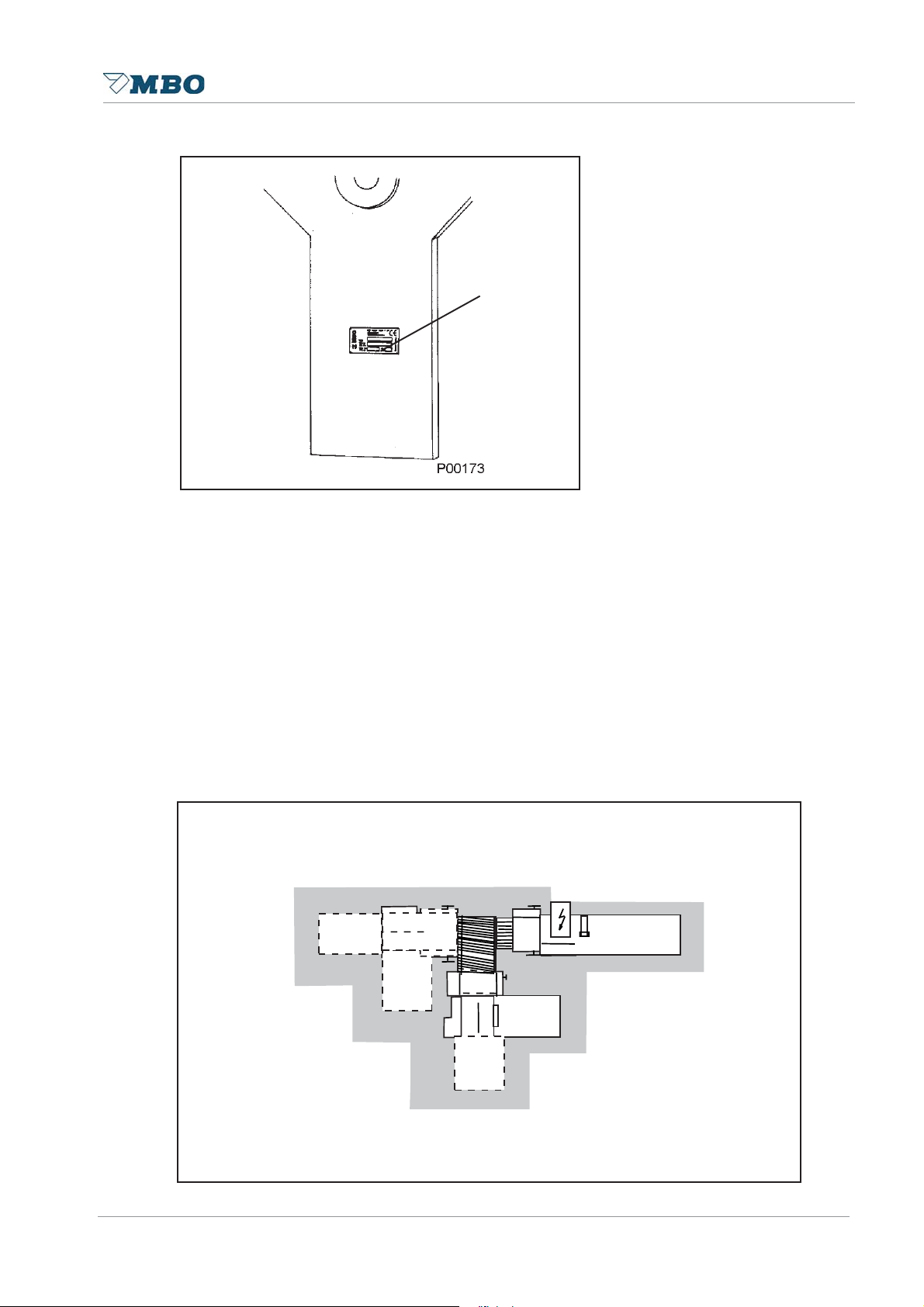
1.2.1 Marking of the product
$
$
$
$
The identification of the machine as well as the most important machines data can be seen at the
machine in the type sign (1).
Operating Manual B21-C - en
1
Allways indicate these statements for the sevice orders and spare part orders:
• Fabrication number
• Serial number
• Machine type
1.2.2 Working area
The represented graphics show the single working area of the machine. The permitted work field
during the operation is marked in grey .
3
Page10Alterations reserved Version 05/2008
Page 11
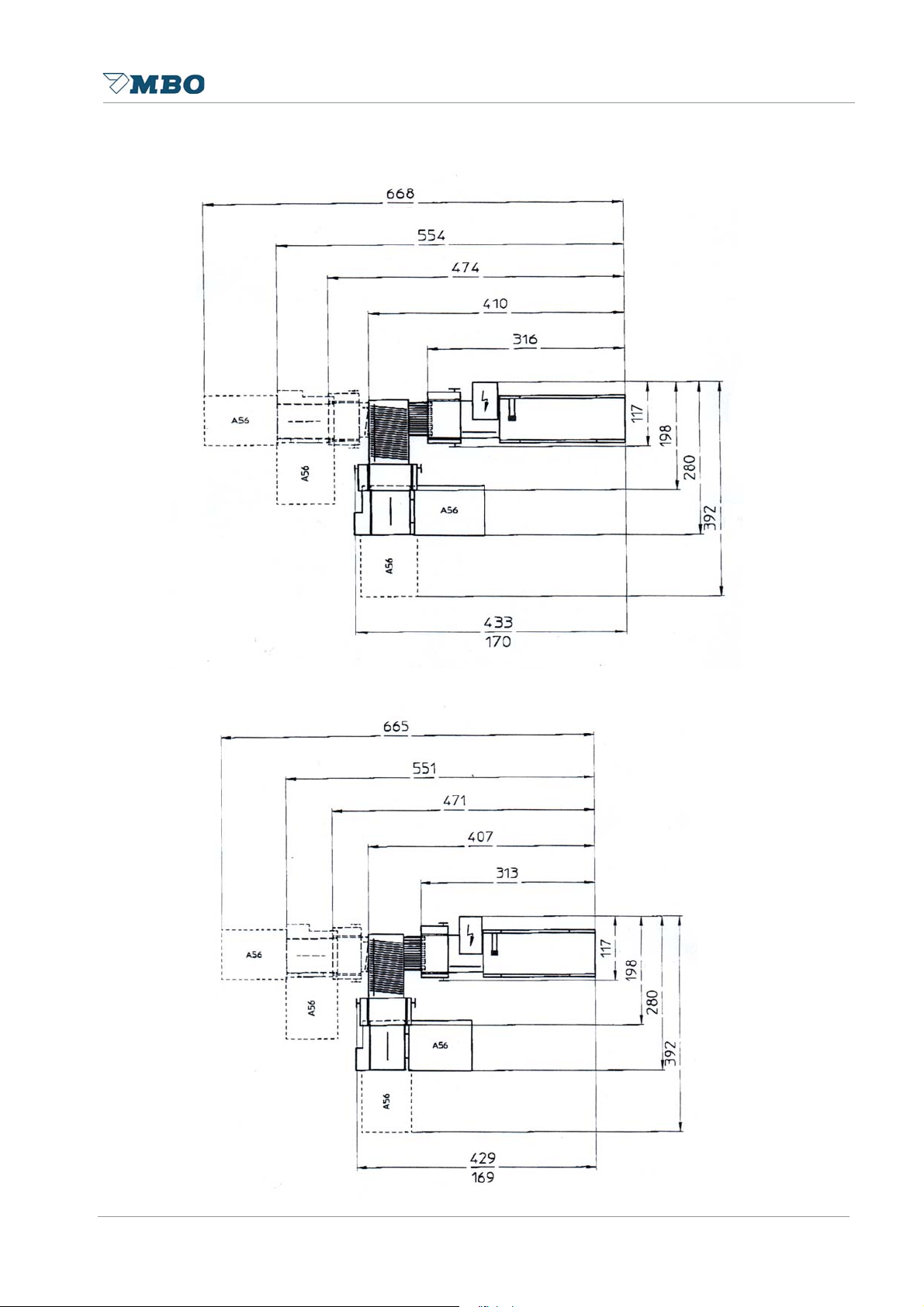
1.3 Product data
1.3.1 Floor plan B21/44X
Operating Manual B21-C - en
1.3.2 Floor plan B21/64X
Measurements in inch
Alterations reserved
Page 11
Measurements in inch
Version 05/2008
Page 12

1.4 Technical Data
Operating Manual B21-C - en
Machine data:
Certif icat ion: Conf ormity certif icat ion:
Sound e mission: Sound emission (Al):
Elect rica l data: W iring diagram no.:
Name:
Customers address:
Machine conf iguration:
Machine- and serial no.:
F eeder t yp:
C o m p r e sso r typ :
G S -Sign no .:
8 page un it
16 page unit
Knif e unit " X"
St ream deliv er y:
O perat ion voltage (V: /Hz:)
Control voltage (V: /A :)
T ot al nominal current (V: /A:)
Main supply f use (A : )
Buckle fol ding machi ne B21
4; 4X; 44; 44X; 6; 6X; 64; 64X; 66; 66X
Continuo us feeder - C
For mats: Minimal format :
Maximal format:
Connect ed wat t age: Parellel unit
(220V;50HZ) Compressor:
Cont inuous feeder 0,1 KW
8 page un it
Knif e unit " X"
St ream deliv er y SE500/ 3; A 56
Wo rk ing speed Min. work ing speed:
Max . w ork ing speed:
6 x 6 inch
21 x 33 inch
0,75 K W
1,5 KW
0,75 K W
0,55 K W
0,12 K W
400 inch/ min.
8000 inch/ min
Page12Alterations reserved Version 05/2008
Page 13

Operating Manual B21-C - en
Net lbs Br ut lbs
Weight in lbs: Continuous feede r 4 buck les 1219 1585
Continuous feede r 6 buck les
Parallel unit 4 buc kles with noise hood 990 1631
Parallel unit 4 buc kles without noise
hood
Parallel unit 6 buc kles with noise hood 1047 1752
Parallel unit 6 buc kles without noise
hood
8pg 4 buckle unit with noise hood
8pg 4 buckle unit withou t noise hood
8pg 6 buckle unit with noise hood
8pg 6 buckle unit withou t noise hood
1234 1600
Knif e unit " X" T530- 4X 595 881
Knife unit " X" T530- 44X 637 926
St ream deliv ery SE 500/ 3 79 235
St ream deliv ery A 56 218 383
1.5 Supplyed documents
Users ma nual: Counter:
Air produc er:
Sequence stat i on:
Wiring diagram no.: Machine:
Sequence stat i on:
Spa re pa rts manual: Mac hi ne: B21 Cont i nuous feeder
Knife unit "X": B21
St ream deli very: SE 500/3 / A56
Sequence uni t :
Knife li st: TM 35/2
Alterations reserved
Page 13
Version 05/2008
Page 14

1.6 Equipment
1.6.1 Buckle folding machine
The buckle folding machine works exclusively in accordance with the principle of buckle folding.
The MBO buckle folding machine B21 with pile feeder has been developed to process sheets in
the sizes of 6 x 6 inch up to 21 x 33 inch. The production speed can be regulated between 400
and 8000 inch/min. However, this result depends on the type and size of sheet and type of fold.
The basic machine consists of a folding unit one with pile feeder as well as the well-proven MBO
register table.
1.6.2 Folding unit one
The folding unit one is equipped with four (optional six) stainless-steel buckle plates, sheet stop
fine adjustment and integrated swing deflectors. Moreover , it is also equipped with the well-proven
MBO spiral foldrollers, which may be adjusted through the quick-setting elements located on top
of the machine, combined with the low-noise belt drive system and solid, quickly removeable
slitter shafts through plug bearings.
1.6.3 Folding unit two
The folding unit two is a mobile buckle folding unit with own drive, register table, a maximum
working width of 21 inch as well as four buckle plates as descriped above.
Operating Manual B21-C - en
1.6.4 Knife folding unit „X“
The knife folding unit “X”, which is equipped with belt drive system, maximum working width of
21inch, and electronical knife control is useable as a folding unit two or three.
The knife folding unit “X” has an own drive and self-control.
1.6.5 Hook on stream delivery
The hook-on stream delivery SE500/3 is available in the configurations B21/4 ; B21/6 ; B21/44 ;
B21/64; B21/66 as standard. The mobile delivery A56 is optional. Machines with a unit ”X”
configuration, 4X ; 6X ; 44X; 64 or 66X, must choose the optional A56 ,because SE500/3 can
not be suspended at the ”X” unit.
The following description from the feeder to the machine should enable the operator to achieve a
general understanding of the machine.
Page14Alterations reserved Version 05/2008
Page 15

Operating Manual B21-C - en
1.7 Functioning description
1.7.1 Functioning description buckle fold
The principle of buckle fold is that
the sheet is always pushed into
the buckle plate.
three foldrollers and one buckle plate
are necessary to prepare a buckle fold.
Foldrollers 1 and 2 carry the sheet into
the buckle plate 4 to the sheet stop.
A buckle occurs during transporation
through these foldrollers to the direction
of foldrollers 2 and 3 by which the sheet
is folded through its passage.
1.7.2 Functioning description knife fold
4
Two foldrollers 1 und 2 as well
as one knife 3 are necessary
to prepare aknife fold.
The sheet is transported under
the knife to a sheet stop and aligned.
After the knife has been released
it moves the sheet between
the foldrollers where it is folded
during its passage.
3
21
Alterations reserved
Page 15
Version 05/2008
Page 16

Operating Manual B21-C - en
Page16Alterations reserved Version 05/2008
Page 17

Operating Manual B21-C - en
2 Safety
2.1 Representation of alerts
2.2.1 Safety references and colours
Representation Meaning
Forbid
Red border
White background
Black symbol
Warning
Y ellow background
Black symbol
Commandment
Blue background
White symbol
Alterations reserved
Page 17
Version 05/2008
Page 18

2.1.2 General dangers signs
Representation Meaning
Operating Manual B21-C - en
Warning of hot surface
Warning of falling objects
Warning of rotating machine parts
Warning of hand injuries
Warning of dangerous electric tension
Caution, danger through stumble places
Caution, lifting of heavy machine parts
Caution, danger through rotating slitter shafts
Caution, danger through rotating chain drive
Page18Alterations reserved Version 05/2008
Page 19

2.1.2 General dangers signs
Representation Meaning
Operating Manual B21-C - en
Caution, danger through rotating belt drives.
Caution before falling down of the opened protection hood.
Caution before flammable agents.
Danger before used cleaning agents and rags.
Warning of a dangerous place.
Alterations reserved
Page 19
Version 05/2008
Page 20

2.1.3 Danger level
Danger level give a reference to the heavy of the danger. They are constructed after a classification
system, which differs through different signal words:
• Danger (Safety signs presented)
• Warning (Safety signs presented)
• Caution (Safety signs presented)
• Caution (without Safety signs)
Danger levels Meaning
'$1*(5
:$51,1*
Operating Manual B21-C - en
A directly threatening danger that leads to heavy injuries or to death.
A possibly dangerous situation that can lead to heavy injuries or to
death.
&$87,21
&$87,21
A possible dangerous situation that can lead to easy personal injury .
A possible dangerous situation that can lead to material damage.
Page20Alterations reserved Version 05/2008
Page 21

Operating Manual B21-C - en
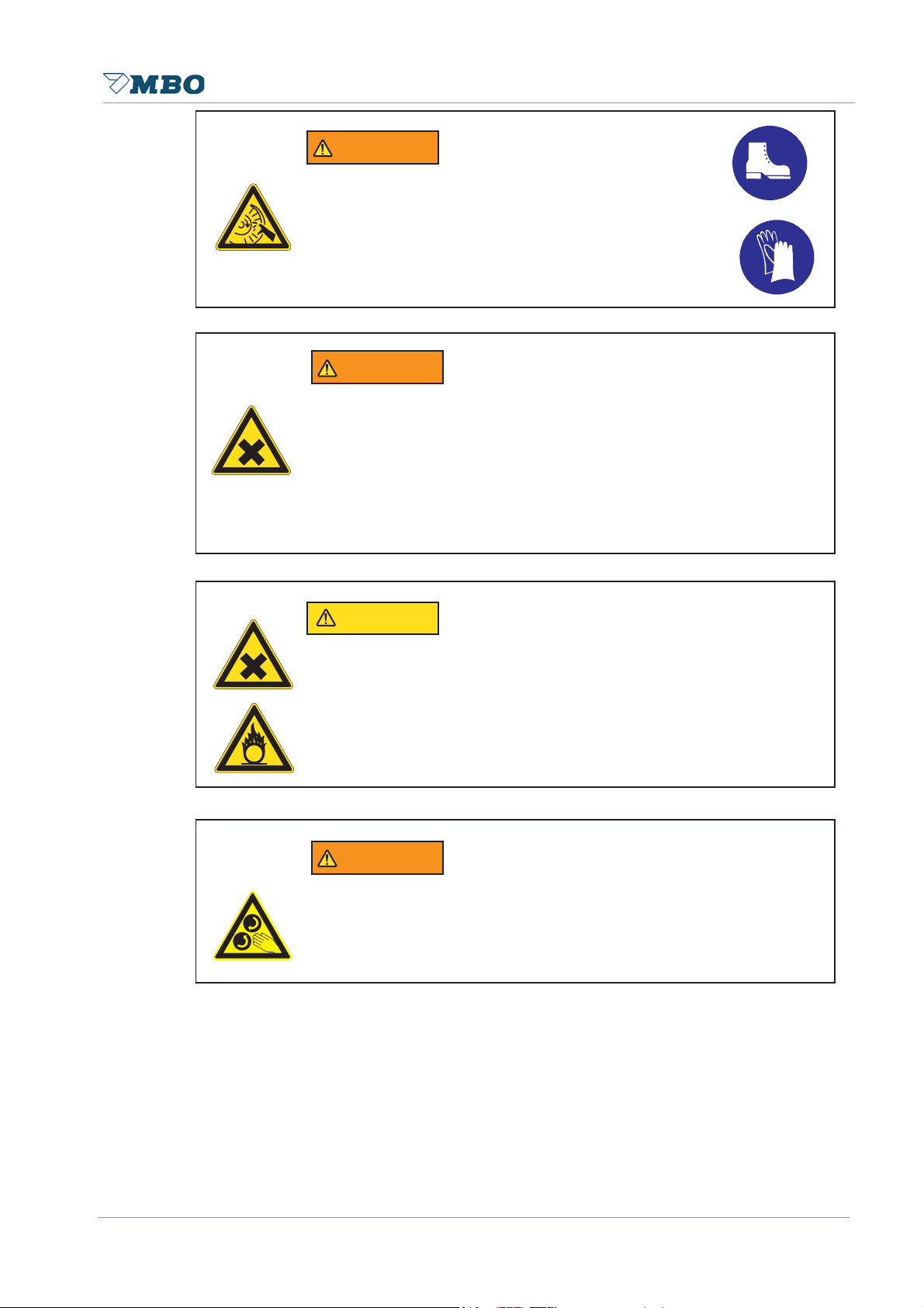
2.1.4 Safety advises at the operators manual
'$1*(5
Danger of electric tension.
Negligence can cause, heavy injuries or death.
Report damaged electrical connections to respnsible supervisor.
'$1*(5
Danger of electric tension at head clams with main switch off.
Negligence can cause, heavy injuries or death.
Work at the electronics can only be carried out of authorized persons or
skilled personnel.
'$1*(5
Danger of electric tension.
Negligence can cause, heavy injuries or death.
• Keep the main control cabinet and the lower distributor cabinet always
locked against unauthorized persons.
• During maintenance working at the control cabinet turn off main switch
and disconnect the network connector.
• Turn off and lock out system power before servicing.
:$51,1*
Danger of running machine parts.
Negligence can cause heavy personal injuries or extensive damages.
Report each audible/visible security-related change of the machine to the
responsible for that in your business.
Alterations reserved
:$51,1*
Danger before running belt-drive.
Negligence can cause, bruise emerges at the hands.
This work should be carried out by one person only !
Page 21
Version 05/2008
Page 22

Operating Manual B21-C - en
:$51,1*
Danger before falling down of the opened protection hood.
Negligence can cause heavy injuries through bruise of body part.
Be sure that in work with opened noise hoods this is completely opened to
the attack.
&$87,21
Danger of stumble places through lying around cables.
Negligence can cause personal injuries.
Place the machines connections (cables, hoses, tubes) so, that they form
no stumble places.
'$1*(5
Danger of running machines part.
Negligence can cause, heavy injuries or death.
• Keep hairs always together bandage and protected.
• T ake by operation and maintenance working at the machine your
jewellery off.
• Carry during operation or maintenance on the machine only adjoining
garment.
'$1*(5
Danger of running machines part.
Negligence can cause, heavy injuries or death.
In sudden stop of the machine, review before turning on:
• That no further person is at the machine.
• That the machine is in a flawless condition.
:$51,1*
Danger of sound pressure.
Negligence can cause, ear damage can emerge.
Use an ear protection for work at the folding machine.
Page22Alterations reserved Version 05/2008
Page 23

Operating Manual B21-C - en
:$51,1*
Danger through maintenance tool.
Negligence can cause heavy personal injuries or extensive damages.
• Use only tools in good working condition.
• Pay attention that after adjustment or maintenance working at the
machine, all tools are removed.
'$1*(5
Danger of running machine parts during the installation work.
Negligence can cause heavy personal injuries or extensive damages.
• Allow service and cleaning works only to be carryed.
• Turn off the machine during maintenance and restoration work by the
main switch.
• Neutralize the electrical cabinet against unintentional switch on.
• Check before turning on, that no further person is at the machine.
&$87,21
Danger through heavy machines components.
Negligence can cause heavy personal injuries or extensive damages.
If the weight amounts more than 25 kg, a further person must be aid for
taken of the components.
:$51,1*
Danger of running machine parts.
Negligence can cause heavy personal injuries or extensive damages.
• Safety switches at the protection and noise hoods can not be
manipulated or modified.
• Adjustments by opened protection hoods are only permited for
setup. Setups can only be performed on machines with electronical
speed regulation.
• Machines with mecanical speed regulation can only be adjusted with
opened protection hoods throught the hand wheel.
Alterations reserved
Page 23
Version 05/2008
Page 24
Operating Manual B21-C - en
:$51,1*
Danger of slitter shafts.
Negligence can cause cut injuries.
• During maintenance work at the slitter shafts, the use of
protection gloves and safteyshoes is required.
• Do not hold the slitter shafts by the tool but always at the
shaft.
:$51,1*
Danger before wrong use of cleansing agents.
Negligence can cause health defects.
• Avoid skin contact.
• Protect yourself against splashes in the eyes.
• Use for cleansing protection gloves.
• Inform yourself through the cleaner manufacturer about remaining
dangers and compatibility for human skin.
&$87,21
Danger before used cleansing rags.
Negligence can cause health defects.
• Note the fire dangers through the flammability of the cleaner .
• Detoxifythe cleaning rags.
• Inform yourself at the cleaner manufacturer about remaining dangers as
well as over the correct disposal.
:$51,1*
Danger of running machines part during the installation working.
Negligence can cause heavy personal injuries or extensive damages.
• Never grasp into the running machine in!
• Keep protection hood close during production.
Page24Alterations reserved Version 05/2008
Page 25
Operating Manual B21-C - en
2.1.5 Dangerous zones / Warning signs at the machine
2.1.5.1 Overview
48
9
5
6
7
3
2
10
1
17
11
15
16
1 Suction wheel
2 Ball bar
3 Fold head - operator side cover
4 Slitter shaft protection
5 Mobile knife folding unit „X“
6 Hand wheel at X-unit
7 Mobile stream delivery A56 (Option)
8 Hand wheel shaft/cleaner roller support
9 Sheet transport 8 and 16 page unit
10 Fold head drive side cover
11 Compressor
12 Main cabinet parallel unit
13 Control cabinet 8 and 16 page unit
14 Control cabinet mobile knife folding unit „X“
15 Control cabinet stream delivery A56
16 Control cabinet hook on stream delivery SE 500/3
17 Feeder drum
14
13
12
Alterations reserved
Page 25
Version 05/2008
Page 26

Operating Manual B21-C - en
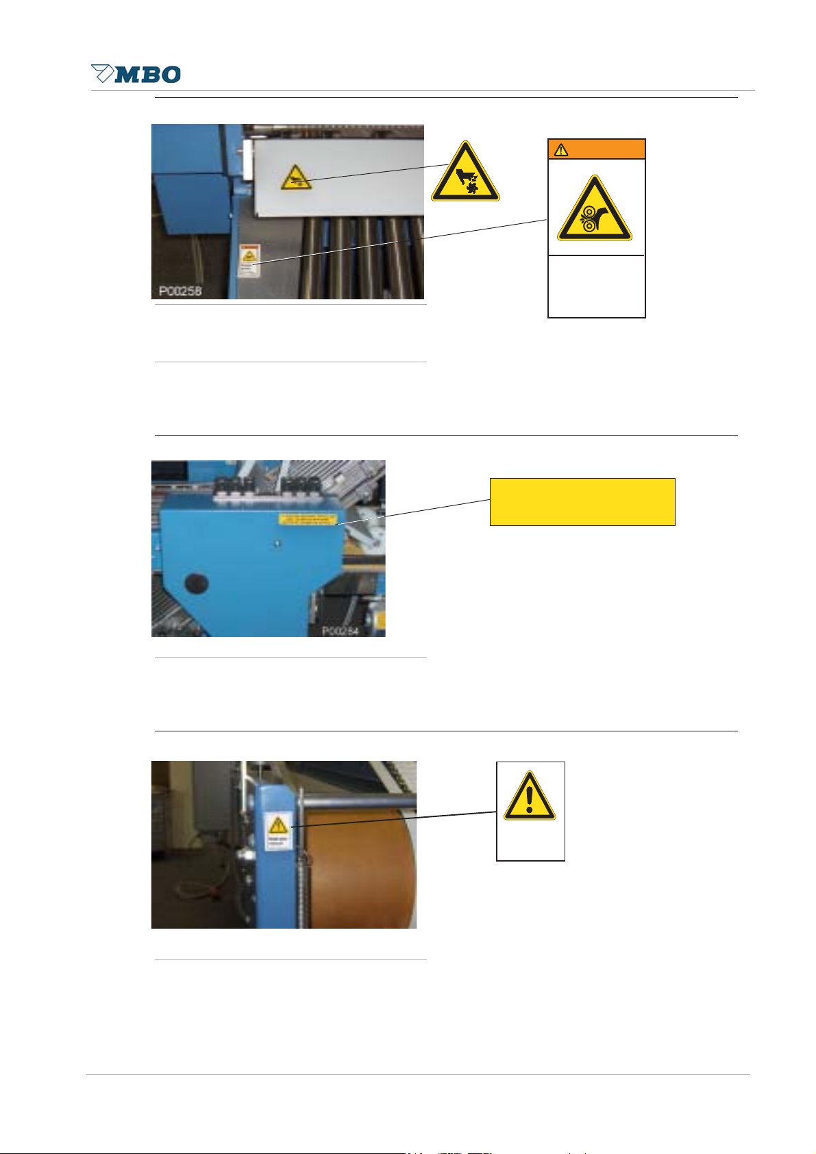
2.1.5.2 Danger references-arrangement and meaning
Pos. 01 Suction wheel
Meaning:
Danger before running suction wheel. Negligence can cause bruises on your hands.
Keep your hands away from the running suction wheel.
Pos. 02 Ball bar
&$87,21
3LQFKSRLQW
KD]DUG
.HHSKDQGV
FOHDU
&$87,21
3LQFKSRLQW
KD]DUG
.HHSKDQGV
FOHDU
Meaning:
Danger before ball bar. Negligence can cause bruises on your hands.
Keep your hands away from this dangerous place.
Pos. 03 Fold head - operator side cover
Meaning:
Warning before moving machine part s in area of fold head - operator side cover. Work only under
super vision of a second person at the machine.
Read and understand operator´s manual before using this machine.
:$51,1*
Ä&$87,21029,1*3$576'2
12723(5$7(0$&+,1(
:,7+287*8$5',13/$&(³
5HDGDQG
XQGHUVWDQG
RSHUDWRUV
PDQXDOEHIRUH
XVLQJWKLV
PDFKLQH
Page26Alterations reserved Version 05/2008
Page 27
Pos.04 Slitter shaft protection
:$51,1*
5RWDWLQJSDUWVDQG
VKDIWFDQFDXVH
VHYHUHLQMXU\
/RFNRXWSRZHUDQG
DOORZPDFKLQHWR
VWRSEHIRUHRSHQLQJ
5HDGDQG
XQGHUVWDQG
RSHUDWRUV
PDQXDOEHIRUH
XVLQJWKLV
PDFKLQH
:$51,1*
:$51,1*
5RWDWLQJSDUWVDQG
VKDIWFDQFDXVH
VHYHUHLQMXU\
/RFNRXWSRZHUDQG
DOORZPDFKLQHWR
VWRSEHIRUHRSHQLQJ
Meaning:
Danger before rotating slitter shafts. Negligence can cause cut or tear off of body parts.
Lock out power and allow machine to stop before opening.
Pos.05 Mobile knife folding unit „X“
Operating Manual B21-C - en
Meaning:
Read and understand operator´s manual before using this machine.
Meaning:
Danger before rotating slitter shafts. Negligence can cause cut or tear off of body parts.
Lock out power and allow machine to stop before opening.
Alterations reserved
Page 27
Version 05/2008
Page 28
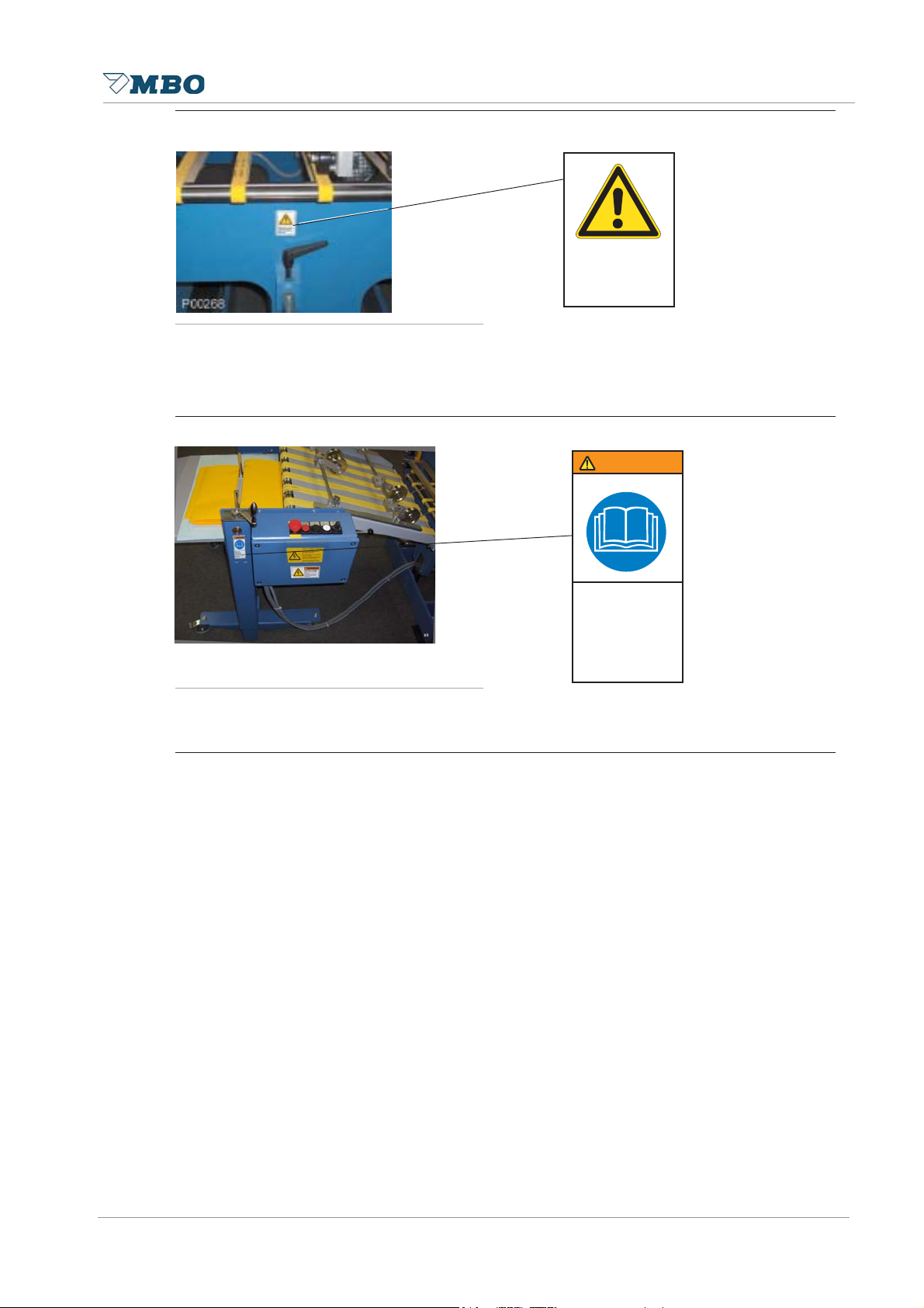
Pos. 06 Hand grip at X-Unit
5HDGDQG
XQGHUVWDQG
RSHUDWRUV
PDQXDOEHIRUH
XVLQJWKLV
PDFKLQH
:$51,1*
Meaning:
Danger before material damages.
Operate X-Unit only with locked hand grip.
Pos.07 Mobile stream delivery A76
Operating Manual B21-C - en
2SHUDWHRQO\
ZLWKORFNHG
NQXUO
Meaning:
Read and understand operator´s manual before using this machine.
Page28Alterations reserved Version 05/2008
Page 29

Operating Manual B21-C - en
.HHSKDQGV
FOHDURIUROOHUV
3LQFKSRLQW
:$51,1*
Pos.08 Hand wheel shaft/cleaner roller support
1
Pos. 1
Pos. 2
:$51,1*
1
1
5RWDWLQJSDUWVDQG
VKDIWFDQFDXVH
VHYHUHLQMXU\
/RFNRXWSRZHUDQG
DOORZPDFKLQHWR
VWRSEHIRUHRSHQLQJ
2
1
Meaning Pos. 1
Danger before rotating machine shafts. Negligence can cause cut or tear off of body parts.
Keep your hands clear of rollers.
Meaning Pos. 2
Danger before rotating slitter shafts. Negligence can cause cut or tear off of body parts.
Lock out power and allow machine to stop before opening.
Alterations reserved
Page 29
Version 05/2008
Page 30
Operating Manual B21-C - en
.HHSKDQGV
FOHDURIUROOHUV
3LQFKSRLQW
:$51,1*
5HDGXVHU
PDQXDO
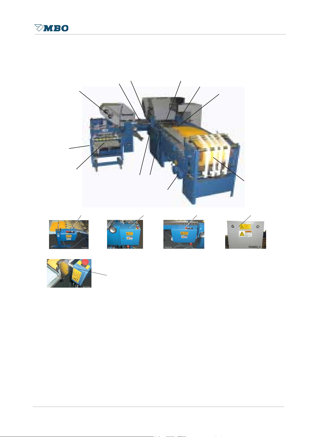
Pos 09 Sheet transport 8 and 16 page unit
Meaning Pos.1
Danger before rotating machine shafts. Negligence can cause cut or tear off of body parts.
Keep your hands clear of rollers.
Meaning Pos.2
Danger before rotating transport rollers at the sheet transport. Negligence can cause bruises on
your hands. Keep hands clear of rollers.
Pos. 10 Fold head drive side cover
Pos. 1
Pos. 2
Meaning:
Warning before moving machine parts in area of parallel fold head-drive side cover . W ork only
under super vision of a second person at the machine.
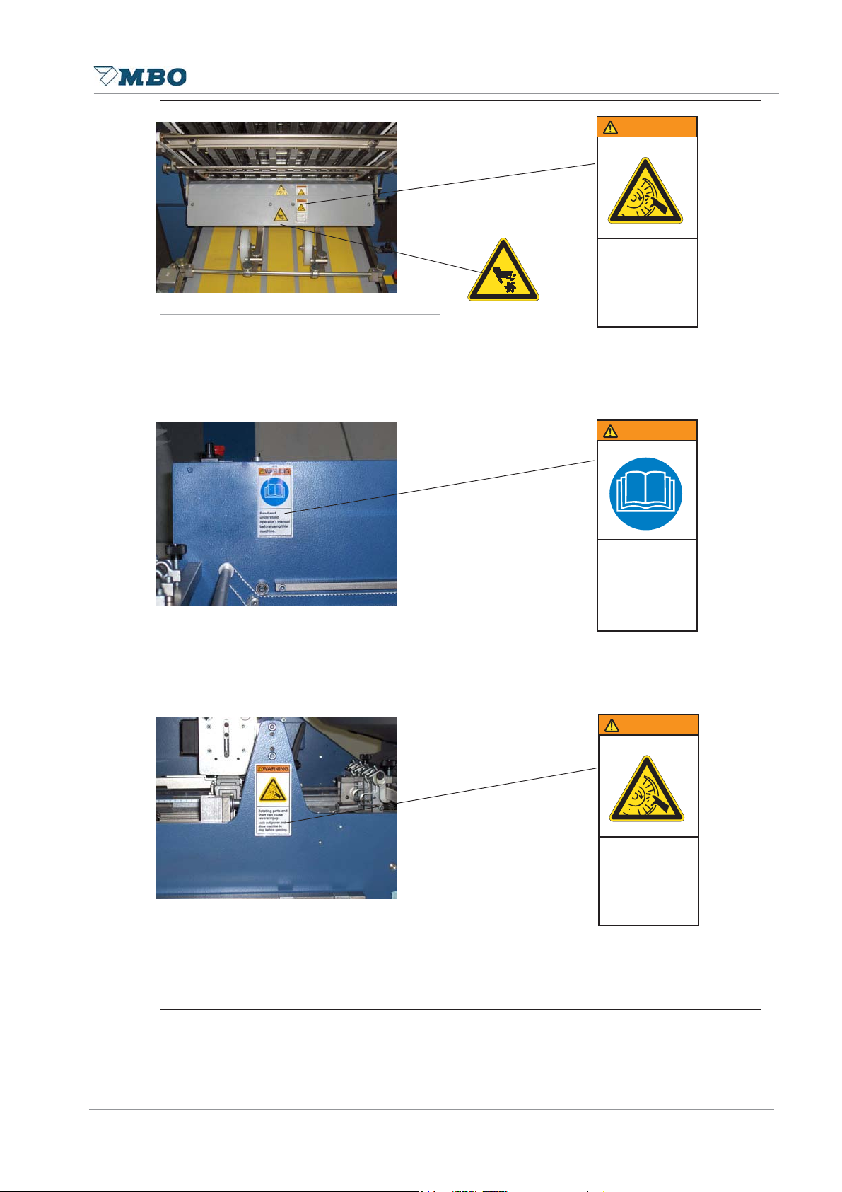
Pos. 11 Sheet guide support
Ä&$87,21029,1*3$576'2
12723(5$7(0$&+,1(
:,7+287*8$5',13/$&(³
Meaning:
Read and understand the operator manual before using this machine.
Page30Alterations reserved Version 05/2008
Page 31

Pos. 12 Main cabinet parallel unit
Operating Manual B21-C - en
9256,&+7$77(17,21$7(17,21
9RUGHPgIIQHQ6FKUDQNLQQHUHV
VSDQQXQJVORVPDFKHQ
3ULRUWRRSHQLQJEHVXUHWKDWLQVLGH
RIFDELQHWLVGHDG
$YDQWGRXYULUYpULILH]TXHOLQWpULHXU
GHODUPRLUHVRLWVDQVWHQVLRQ
$QWHVGHDEULUDVHJXUDUVHTXHHO
LQWHULRUGHODUPDULRHVWHVLQGWHQVLyQ
+D]DUGRXVYROWDJH
5LVNRIHOHFWULFVKRFN
RUEXUQ
7XUQRIIDQGORFNRXW
V\VWHPSRZHUEHIRUH
VHUYLFLQJ
&KDUDFWHULVWLFIRU
DOOIXVHV
PHGLXPWLPHODJ
86(&233(5
:,5(21/<
Pos.1
:$51,1*
Pos.2
Pos.3
Pos.4
Meaning Pos.1 und Pos. 2:
Hazardous voltage. Negligence can cause electric shock or burn.
Turn off and lock out system power before servicing.
Meaning Pos.3:
Replacement of fuses only with same specification.
Meaning Pos.4:
Use copper wire only!
Pos. 13 Control cabinet 8 and 16 page unit
Meaning:
Hazardous voltage. Negligence can cause electric shock or burn.
Turn off and lock out system power before servicing.
9256,&+7$77(17,21$7(17,21
9RUGHPgIIQHQ6FKUDQNLQQHUHV
VSDQQXQJVORVPDFKHQ
3ULRUWRRSHQLQJEHVXUHWKDWLQVLGH
RIFDELQHWLVGHDG
$YDQWGRXYULUYpULILH]TXHOLQWpULHXU
GHODUPRLUHVRLWVDQVWHQVLRQ
$QWHVGHDEULUDVHJXUDUVHTXHHO
LQWHULRUGHODUPDULRHVWHVLQGWHQVLyQ
:$51,1*
+D]DUGRXVYROWDJH
5LVNRIHOHFWULFVKRFN
RUEXUQ
7XUQRIIDQGORFNRXW
V\VWHPSRZHUEHIRUH
VHUYLFLQJ
Alterations reserved
Page 31
Version 05/2008
Page 32

Operating Manual B21-C - en
Pos. 14 Control cabinet mobile knife folding unit „X“
Meaning:
Hazardous voltage. Negligence can cause electric shock or burn.
Turn off and lock out system power before servicing.
Pos.15 Control cabinet stream delivery A56
9256,&+7$77(17,21$7(17,21
9RUGHPgIIQHQ6FKUDQNLQQHUHV
VSDQQXQJVORVPDFKHQ
3ULRUWRRSHQLQJEHVXUHWKDWLQVLGH
RIFDELQHWLVGHDG
$YDQWGRXYULUYpULILH]TXHOLQWpULHXU
GHODUPRLUHVRLWVDQVWHQVLRQ
$QWHVGHDEULUDVHJXUDUVHTXHHO
LQWHULRUGHODUPDULRHVWHVLQGWHQVLyQ
:$51,1*
+D]DUGRXVYROWDJH
5LVNRIHOHFWULFVKRFN
RUEXUQ
7XUQRIIDQGORFNRXW
V\VWHPSRZHUEHIRUH
VHUYLFLQJ
9256,&+7$77(17,21$7(17,21
9RUGHPgIIQHQ6FKUDQNLQQHUHV
VSDQQXQJVORVPDFKHQ
3ULRUWRRSHQLQJEHVXUHWKDWLQVLGH
RIFDELQHWLVGHDG
$YDQWGRXYULUYpULILH]TXHOLQWpULHXU
GHODUPRLUHVRLWVDQVWHQVLRQ
$QWHVGHDEULUDVHJXUDUVHTXHHO
LQWHULRUGHODUPDULRHVWHVLQGWHQVLyQ
Meaning:
Hazardous voltage. Negligence can cause electric shock or burn.
Turn off and lock out system power before servicing.
Pos. 16 Control cabinet hook on stream delivery SE 500/3
Meaning:
Hazardous voltage. Negligence can cause electric shock or burn.
Turn off and lock out system power before servicing.
:$51,1*
+D]DUGRXVYROWDJH
5LVNRIHOHFWULFVKRFN
RUEXUQ
7XUQRIIDQGORFNRXW
V\VWHPSRZHUEHIRUH
VHUYLFLQJ
9256,&+7$77(17,21$7(17,21
9RUGHPgIIQHQ6FKUDQNLQQHUHV
VSDQQXQJVORVPDFKHQ
3ULRUWRRSHQLQJEHVXUHWKDWLQVLGH
RIFDELQHWLVGHDG
$YDQWGRXYULUYpULILH]TXHOLQWpULHXU
GHODUPRLUHVRLWVDQVWHQVLRQ
$QWHVGHDEULUDVHJXUDUVHTXHHO
LQWHULRUGHODUPDULRHVWHVLQGWHQVLyQ
Page32Alterations reserved Version 05/2008
Page 33

2.2 Product security
2.2.1 Obligation and liability
Note references in the operation instructions:
Prerequisite for safety and free interference working with this machine is the knowledge of the
basic safety references and the safety prescript.
This operating instruction is to be noted by all persons, who work at the machine. In addition all rules
valid for accident prevention has to be noted.
Potential danger while operating with machine:
The Buckle folding machine is after the state of the technology and that acknowledged safety
rules constructed. Nevertheless dangers for body and life of the unser or third and/or inpairment
can emerge in its use at the machine or at other material asset.
The machine is to be used only:
• For the due use
• In safety flawless condition
Interferences, which can impair the safety , are to be removed immediately .
Operating Manual B21-C - en
Guarantee and liability
Herefor our general sale and delivery conditions has to be concerned. The Guarantee and liability
claims with personal injuries and equipment damages are not excluded if they are to be led back to
one or several of the following causes:
• Due use of the machine,
• Improber installation, do into operation, serving and maintenance of the machine,
• Operating of the machine in defective safety arrangements or not regular appropriate or not
operable safety devices and protection devices,
• Not following of the references in the operating instructions regarding carrier, storage,
assembling, starting, operating, maintenance and mobilizing of the machine,
• Independent structural variations at the machine,
• The not keeping of maintenance and cleaning intervals that exclude a standstill of the
machine,
• Deficient supervision of machines part, that a wear be subject,
• Bad servicing and damages through foreign objects.
Alterations reserved
Page 33
Version 05/2008
Page 34

2.2.2 Due use
• The machine is intended only for the folding, designing, perforating and cutting of paper.
• The machine is displayed only for the one-man-operation.
• The machine can only be operated in a flawless technical condition. Interferences, which
endanger the safety , must immediately be removed by instructed persons or from
manufacturer or from supplier.
• The machine can only be operated of seviced by skilled and autorized personnel. Machine can
only be operated/serviced by persons older than 18 years.
2.2.3 Inappropriate use is:
• An other use of the machine as folding, designing, perforating and cuttting of paper .
• Working of other materials as a paper .
• Manipulating and independent modification of the machine.
• Removing of protection and safety devices from the machine.
• Operating of the machine without instructed or trained personal.
• Operating / maintenance by persons younger than 18 years.
• Operating of the machine without instructed or trained personel.
The manufacturer and/or supplier is not responsible for all damages, that develop from inappropriate
use.
Operating Manual B21-C - en
Page34Alterations reserved Version 05/2008
Page 35

Operating Manual B21-C - en
2
6
5
41311
0
617
2.3 Protection guard -general plan
2.3.1 Protection guard - general plan of machine
1
8 1
1
1
1
5
3
6
2
4
9
7
1
1
Alterations reserved
Page 35
Version 05/2008
Page 36

Operating Manual B21-C - en
0
2.3.2 Protection guard list 8 and 16pg unit
123
1
5
9
6
4
7
8
Page36Alterations reserved Version 05/2008
Page 37

Operating Manual B21-C - en
2.3.3 Protection guard list knife folding unit „X“
6
5
4
7
3
2
1
Alterations reserved
Page 37
Version 05/2008
Page 38

Operating Manual B21-C - en
2.3.4 Protection guard list Delivery A56
3
1
2
Page38Alterations reserved Version 05/2008
Page 39

Operating Manual B21-C - en
2.4 Organisational and personnel
2.4.1 Working safety
• Preserve the operationg instructions manual permanently at the machine regarding to the
operating instructions the universally valid local regulations to the accident prevention and to
the environmental protection.
• Keep all safety references and dangers references at the machine in readable conditions.
• Review the safety references and dangers references occasionally .
2.4.2 Demands on the operating personnel
This table represents the jurisdictions and the different activities of person groups, which work at
the machine.
Instructed
Persons
Transport and pack i ng
Mechanic firm
Custom er s ervi c e
Responsable
supervisor
Starting
Operation
Troubleshoot i ng mec hanic all y
Interference removal el ectric all y
Arrange, mobi li z ing
Maintenance
Restoration
Out of order, storage
2.4.3 Qualification and training
Ensure that the operating personal was trained with the machine and that the operating manual
was read. A correct operating of the machine can prevent severe injuries to the operator and third
persons as well as material damages.
Attend to following references:
• Permit only trained and on manner personnel work at the machine.
• The user information must be read and understood by the operating and maintenance
personnel.
• Determine clearly the responsibility of the personnel for operating, converting and
maintenance.
• Let only trained personnel work at the machine under supervision of a trained person.
• Instruction must be receipt in written form.
Alterations reserved
Page 39
Version 05/2008
Page 40

Operating Manual B21-C - en
2.5 Personal protection equuipment
:$51,1*
Danger of sound pressure.
Negligence can cause, ear damage.
Use an erar protection for work at the folding machine.
:$51,1*
Danger before slitter shafts.
Negligence can cause, cut injuries can emerge.
Carry protection gloves and safety shoes while maintenance
work.
2.6 Tasks for Emergency
2.6.1 Rescue of per son s
1 Urgent measures Rescue the injured person.
2 Emergency call Telephone no.:.................. (Register number)
3 First aid Secure the accident place
Replace vital functions again, hold this
uprightly
Avoiding further damage.
Who reports?
What happened?
How many are injured?
Where happened?
Which type of injuries?
Wait for check response!
Further care of the injured: Confortable and correct situation
Calming encouragement
St able if fractures
Place bandages on open wounds.
4 Further measures Advise/inform rescue service
Keep curious persons away .
Page40Alterations reserved Version 05/2008
Page 41

Operating Manual B21-C - en
2.6.2 Emerging substances
Concern the factory directives with its statements in the fire case. Depend on the given directions.
Is this not by hand advance so:
2.6.2.1 Solvent degreasing out of hydrocarbons
• Inform superior.
• Emerging of the material: in larger quantities supply immediately for fresh air and leave the
location.
• Slight spill quantities absolve with allocated binding agent.
• In case of fire extinguish only with extinguisher located to this.
• Notify immediately First helper and supervisor.
• Wash off in skin contact with much water and skin cleaner.
• By eye contact rise with much water (eye shower).
• After inhaling of softening, reach for fresh air .
• Carry unconscious persons immediately to the fresh air.
2.6.2.2 Inflammable degreasing solvents out of not water mixable hydrocarbons (ex. petroleum,
test gasoline, Naphtene: Cyclohexan)
• Disengage inflammation of the material: Unit, leave dangers area and inform layer master.
• Use extinguish: Coal dioxide (CO2), foam, powder extinguisher or water as spray ray .
• Leakage: Slight spill quantities absolve with allocated binding agent.
• Gather remainder materials and refuse in containers planned for that.
• Eyes: Rise immediately with much water at least 10 minutes and search for physician.
• Skin: Rise concerned skin place with much water.
• Inhaling: Worry immediately for fresh air. Keep quietly and hold warm search for physician.
• Swallowing: Search immediately for medical help.
2.6.2.3 Cleaner with watery alkaline cleaning solution:
• Leakage: Inform superior. S pill quantities absolve with allocated binding agent. Clean slight
quantities with much water.
• Accidents: Inform first helper and superior.
• Irritation of skin or eyes rise with much water.
• In swallowing of the concentrate rise mouth drink much water.
• Search for after swallowing of concentrate or continuous irritation medical help.
2.6.2.4 Cleaner BG5-9, weakly alkaline:
• Leakage: Neutralize of initiating running out of little quantities into the discharge channel.
• Eyes: Rise immediately with a lot water at least 10 minutes and search for physician.
• Skin: Rise concerned skin with a lot water.
• Inhaling: Go immediately for fresh air. Keep calm and hold warm and contact medical
assistance.
• Swallowing: Immediately contact medical assistance and show label safety data sheet.
Alterations reserved
Page 41
Version 05/2008
Page 42

Operating Manual B21-C - en
3.0 Transportation, assembly and inst allation
This part of the Operating Manual is directed to the service personnel and internal authorized
personnel.
&$87,21
Danger through heavy machines components.
Negligence can cause heavy personal injuries or extensive damages.
If the weight amounts more than 25 kg, a further person must be aid for
taken of the components.
:$51,1*
Danger before turn of component during the unloading and
assembling process.
Negligence can cause heavy personal injuries or extensive damages.
• Note the weight statement for the carrier under chapter „technical data“.
• Use the forklift for transportation.
• Arrange additional personnel for unloading and setting up. Some
machine groups must be additionaly secured and supported.
3.1 Transportation
3.1.1 Feeder
The folding unit one and the continuous
feeder are delivered in separate crates.
Carry the pallet with a fork lift as close
as possible to its final position.
Unscrew continuous feeder from the
pallet. You should hang tm ropes on the
points 6 and 7 and lift it minimal with the
use of a fork lift. Remove the pallet and
set the continuous feeder to its final
position.
6
7
Page42Alterations reserved Version 05/2008
Page 43

3.1.2 Parallel unit
The folding unit I, completely mounted with
pile feeder, is delivered in one crate. Carry the
pallet with a fork lift as close as possible to
its final position. Unscrew the machine off the
pallet and set the fork lift to the tiebars 1.
Remove the pallet and set the folding unit to
its final position.
Operating Manual B21-C - en
1
3.1.3 8 and 16pg unit
Make sure that machine rollers 3 and guide
roller 5 will not be damaged when taking the
unit of the pallet.
Unscrew the folding unit II off the pallet and
set the fork lift to the tiebar 4.
Two additional persons are also required to
hold the unit. Remove the pallet and carry the
unit to its final position.
3
4
5
Alterations reserved
Page 43
Version 05/2008
Page 44

Operating Manual B21-C - en
3.1.4 Mobile knife folding unit “X”
:$51,1*
Danger before turn of component during the unloading and
assembling process.
Negligence can cause heavy personal injuries or extensive damages.
• Secure the knife folding unit to prevent it from falling over or sliding!
Arrange additional personnel for unloading and setting up.
Unscrew the knife folding unit “X” off the
pallet, set the fork lift onto the frame 1,
and remove the pallet. Affix the four guide
wheels 2 and let the knife folding unit
carefully down
3.1.5 Mobile stream delivery
:$51,1*
Danger before turn of component during the unloading and
assembling process.
Negligence can cause heavy personal injuries or extensive damages.
• Secure the mobile stream delivery in addition with two persons off. Be
careful that by dropping it is not damaging the guide rollers and
machine rollers.
Unscrew the stream delivery and lift it
with two additional persons off the pallet.
2
1
A56
Clean all machine parts (folding units and deliveries) with rust preventing agents!
Page44Alterations reserved Version 05/2008
Page 45

Operating Manual B21-C - en
3.2 Assembly and installation of machine
Carry the machine to its final position.
Plastic feets 3 must be placed
underneath the eight levelling bolts. Level
out the machine by means of these
levelling bolts. Alignments should be
made in crossdirection on the upper, free
accessible foldroller 2.
Levelling should be made also in
longitudinal direction on side frames 1
at left and right side.
Insert the buckle plates. Detach the
guide rails at register table and affix
slitter shafts. All these works are
descriped under the following category
“Operation of the Machine”.
3.3 Electrical connection
2
1
4
3
1
3
3
'$1*(5
Danger of electric tension.
Negligence can cause, heavy injuries or death.
Report damaged electrical connections to respnsible supervisor .
'$1*(5
Danger of electric tension at head clams with main switch off.
Negligence can cause, heavy injuries or death.
Work at the electronics can only be carried out of authorized persons or
skilled personnel.
Alterations reserved
Page 45
Version 05/2008
Page 46

Operating Manual B21-C - en
'$1*(5
Danger of electric tension.
Negligence can cause, heavy injuries or death.
• Keep the main control cabinet and the lower distributor cabinet always
locked against unauthorized persons.
• During maintenance working at the control cabinet turn off main switch
and disconnect the network connector.
• Turn off and lock out system power before servicing.
3.3.1 Control cabinet
Unpack the control cabinet 5 and fasten
it onto the side panel of the register table
6 as well as onto the angled backplate 7
at the feeder. Insert the plugs of the
feeder and the machine into the sockets
of the control cabinet. Plugs as well as
sockets bear the same marking.
Connect the cable of the feeder motor,
machine motor , sockets for auxiliary
folding units as well as the connection
cable of the compressor directly to the
motor protective switch inside the main
control panel according to the attached
wiring diagram.
5
7
6
Page46Alterations reserved Version 05/2008
Page 47

3.3.2 Main current connection
&$87,21
Make sure that power supply and frequency correspond with the data of
your machine! These data should be checked with the label on the side of
the control cabinet.
&$87,21
Consider Clockwise rotating field! A fter wiring has been completed the
terminals must be protected with cover plates provided .
'$1*(5
Operating Manual B21-C - en
After connections have been completed check the rotating field of motors
as described under item 3.3.1. However, if one of these motors should
have the wrong rotating field, change the connection of the individual motor
at the terminal. Turn OFF the machine immediately, if direction of pile plate
does not correspond with switch position 1.10 at main control panel.
Otherwise the limit switch control will not function properly and switch
OFF! This may cause serious personal injuries or extensive damage to the
feeder !
Insert the cable in the base of the control cabinet and connect it with the main terminals provided
according to the attached wiring diagram.
3.3.3 Stream delivery
Danger, the printed circuit board (p.c.b.) of the stream delivery is
provided with 220 voltages!
Negligence can cause heavy injuries or death.
If you are working on the opened cabinet of the delivery make sure that no
power is supplied or do not touch this p.c.b!
'$1*(5
Alterations reserved
Page 47
Version 05/2008
Page 48

4.0 Maintenance
This part of the Operating Manual is directed to the competent service personnel and internal
authorized personnel.
Danger through maintenance tool.
Negligence can cause heavy personal injuries or extensive damages.
• Use only tools in good working condition.
• Pay attention that after adjustment or maintenance working at the
machine, all tools are removed.
Danger of running machine parts.
Negligence can cause heavy personal injuries or extensive damages.
• Safety switches at the protection and noise hoods can not be
manipulated or modified.
• Never carry out foldroller settings while machine is still running.
• Even manual foldroller setting by the handwheel.
Operating Manual B21-C - en
:$51,1*
'$1*(5
Danger of running machine parts during the installation work.
Negligence can cause heavy personal injuries or extensive damages.
• Allow service and cleaning works only to be carryed.
• Turn off the machine during maintenance and restoration work by the
main switch.
• Neutralize the electrical cabinet against unintentional switch on.
• Check before turning on, that no further person is at the machine.
:$51,1*
Danger of slitter shafts.
Negligence can cause cut injuries.
• During maintenance work at the slitter shafts, the use of
protection gloves and safteyshoes is required.
• Do not hold the slitter shafts by the tool but always at the
shaft.
Page48Alterations reserved Version 05/2008
Page 49

Operating Manual B21-C - en
4.1 Tensioning or exchange of belts/tapes
127,&(
The tension of drive belts, and especially for foldrollers and slitter shaft drives should be checked
periodically , i.e. monthly . The drive belt s must be tensioned to such an extent that the foldrollers
cannot manually be held if the machine is turned by handwheel.
:$51,1*
Danger before running belt-drive.
Negligence can cause, bruise emerges at the hands.
This work should be carried out by one person only !
4.1.1 Upper feeder transport tape
For an undisturbed transport, the upper
transport tape (1) must be strained
tightly . Re-strain the tape if required:
Turn both screws (2).
The adjustment must be undertaken on
both sides equal.
The tape will be led by disks (3)
4.1.2 Lower feeder transport tape
For an undisturbed transport, the upper
transport tape (1) must be strained
tightly . Re-strain the tape if required:
Turn both screws (2). The adjustment
must be undertaken on both sides equal.
The tape will be led by disks (3).
1
3
2
4
6
Alterations reserved
Page 49
5
2
Version 05/2008
Page 50

Operating Manual B21-C - en
4
4.1.3 Feeder chain
T est the feeder chain occasionally for it s
tension and re-strain if necessary .
Strain the drive chain (2) with the chain
tensioner (1).
4.1.4 Alignment tape at register table
1 2
Loosen screw 5 and 6 release tension of
tape. For threading/rethreading unhinge
the lattice-type alignment table at pos. 3.
Loosen screw 2, push back the rod 1 in
direction of drive side, remove tape from
the rollers and rethread at pos. 4. Install
new tape in the opposite sequence and
tension it through
screw 6.
Adjustment for centre running of tape
occurs through screw 8.
For this purpose loosen the screw 9
(screw 8 and 9 are located at the internal
side) and fasten it again after completion.
Thereafter, check again and, if
necessary , make necessary corrections.
1
2
3
65
4
8 9
Page50Alterations reserved Version 05/2008
Page 51

Operating Manual B21-C - en
4.1.5 Drive belt for suction wheel
The drive belt 2 is tensioned by means of
tensioning lever 1.
1 2
4.1.6 Drive belt for foldrollers and slitter shaft at parallel unit
The drive belt 4 is tensioned by means of
tensioning lever 3.
4.1.7 Main drive of parallel unit
The poly-V-belt 5 coming from the main
drive shaft 7 to the parallel unit is
tensioned by means of tensioning
lever 6.
3
4
5
6
7
Alterations reserved
Page 51
Version 05/2008
Page 52

Operating Manual B21-C - en
4.1.8 Drive belt for foldrollers at parallel unit and slitter shafts at subsequent unit
See item 4.1.3 page 49.
4.1.9 Drive belt at register table of following folding unit
:$51,1*
Danger befor running belt drive.
Danger of injuries to fingers.
This work should be carried out by one person only !
The drive belt 6 should be tensioned by
means of tape tensioner 5.
5
6
&$87,21
Danger, overstretching of the drive belt.
Negligence can cause material damage.
Let the folding unit run by turning the hand wheel. At the same time the
cross rollers must be easy to stop with the other hand.
Page52Alterations reserved Version 05/2008
Page 53

Operating Manual B21-C - en
4.1.10 Drive belt for foldrollers and slitter shafts of knife folding unit “X”
The drive belt 5 is tensioned by means of
tensioning lever 6.
127,&(
All tapes and belts should be correctly
tensioned as described under item 4.1.
4.1.11 Setting of air gap for knife coupling of knife folding unit “X”
The nominal air gap can be set easily
and without any difficulties through two
setting screws. It is not necessary to
dismantle the COMBIBOX. All you need
is a hexagon key , a C-wrench as well as
a feeler gauge to check the nominal air
gap.
Setting instruction 4.5
1. Remove both access plugs.
2. Loosen both counter nuts.
3. Insert feeler gauge at both sides
between rotor and armature and
turn in the locking screws to such
an extent that you reach the
nominal air gap of 0.15 - 0.20 mm.
Check if gap is equal at both
sides.
4. Retension counter nuts whereby
the locking screws should not
change the position previously set.
5. Mount both access plugs.
Alterations reserved
Page 53
Version 05/2008
Page 54

Operating Manual B21-C - en
4.2 Lubrication / Cleaning
127,&(
Generally , the machine should be cleaned after each job, particularly moveable part s which have
been changed due to change of sheet size, because heavy dust may cause reduction of function.
4.2.1 Main machine including register table
1 2
Clean dust off guide shaft 2 for change of
sheet size at register table as well as
drive shaft 1 and supply a slight touch of
oil.
Safety handwheels should also
occasionally be relubricated at nipples 3.
4.2.2 Continuous feeder R
Clean drive chain 4 grease slightly .
3
4
4.2.3 Guides of pressure bars / Bearings of foldrollers
Supply a slight touch of oil to all
pressure bars of foldrollers and slitter
shafts in all folding units 6 as well as
between the machine panel and bearing
levers 5, monthly (also parallel unit).
Page54Alterations reserved Version 05/2008
5
6
Page 55

Operating Manual B21-C - en
4.2.4 Coupling of knife folding unit “X”
Provide a slight touch of oil to all knife
guides with ball-type nipple, monthly .
127,&(
Just use a few drops of oil because too
much lubricant may drop onto the sheets
through the knife guide!
4.2.5 Guide rails / sheet stop (knife folding unit “X”)
1
Clean dust off the guide rails of the
sheet stop 2 from to ensure perfect
condition of stop guides.
4.2.6 Cleaning of foldrollers
:$51,1*
Danger before wrong use of cleansing agents.
Negligence can cause health defects.
• Avoid skin contact.
• Protect yourself against splashes in the eyes.
• Use for cleansing protection gloves.
• Inform yourself through the cleaner manufacturer about remaining
dangers and compatibility for human skin.
2
Alterations reserved
:$51,1*
Danger before running machine elements.
Negligence can cause bruise at the hands.
Fold rollers should be cleaned only if the machine is not in motion! Push
the Emergency Stop button and/or turn OFF main switch. Ensure that the
machine cannot be re-started!
Page 55
Version 05/2008
Page 56

Operating Manual B21-C - en
&$87,21
Danger before used cleaning rags.
Negligence can cause health defects.
• Note the fire dangers through the flammability of the cleaner .
• Detoxifythe cleaning rags.
• Inform yourself at the cleaner manufacturer about remaining dangers as
well as over the correct disposal.
Depending on the extent of ink build-up, the foldrollers must be cleaned from time to time. The
affect of printing powder or ink build-up on the foldrollers may decrease the quality of the folding.
The rollers must be cleaned with a cleansing agent suitable for the synthetic material. Please
contact your machine supplier . Improper cleaner may cause decomposure or swelling of the
foldroller coating.
MBO - the manufacturer of this folding machine recommends a cleaning material for the foldrollers
made by V ARN, bearing the no. V ARN -W ash VM 111 or VWM. Our recommendation is on a label
near the foldrollers.
The V ARN company is a worldwide supplier for the printing industry . Therefore, it cannot be
excluded that in certain other countries different indications are used. Please take the individual
order no. from the technical data sheets of V ARN.
4.2.7 Compressor
Essential maintenance:
T o ensure full efficiency , however , the
Filter cartridge at suction side should be
checked and cleaned occasionally . The
Filtre cartridge must be cleaned every 50
HOURS OF OPERATION (see page 58)
and be exchanged every 3.000 hours of
operation, according to manufacturers
statement. Dirty or damaged cartridges
must be replaced immediately . Do not
remove the filter cartridge with the
compressor running, otherwise
penetration of foreign substances may
damage the compressor. Make sure that
compressor is turned OFF during
maintenance work.
Exchange of admission filter:
Turn the compressor switch OFF and / or the main supply OFF. Make sure that no other person
can turn ON the pump.
Open the clips 3, remove the guard 4 and the cartridge 5. Clean the cartridge (blow throught
inside to outside) and replace it if it is necessary.
Replacement occures every 6 mounth.
Page56Alterations reserved Version 05/2008
Page 57

Operating Manual B21-C - en
5.0 Operation of the machine
In addition to the numbers the operating sequences to operate the machine are marked with B.
'$1*(5
Danger of running machines part.
Negligence can cause, heavy injuries or death.
• Keep hairs always together bandage and protected.
• T ake by operation and maintenance working at the machine your
jewellery off.
• Carry during operation or maintenance on the machine only adjoining
garment.
:$51,1*
Danger of sound pressure.
Negligence can cause, ear damage can emerge.
Use an ear protection for work at the folding machine.
'$1*(5
Danger of running machines part.
Negligence can cause, heavy injuries or death.
In sudden stop of the machine, review before turning on:
• That no further person is at the machine.
• That the machine is in a flawless condition.
:$51,1*
Danger of running machine parts.
Negligence can cause heavy personal injuries or extensive damages.
• Never carry out foldroller settings while machine is still running.
• Even manual foldroller setting by the handwheel.
Alterations reserved
Page 57
Version 05/2008
Page 58

B 1.0 Main control panel
2
8
920
123
7
6
5
413
7
4
629
0
8112225
For more information see separated operating manual “MS - Control”.
127,&(
Operating Manual B21-C - en
2
2
9
1
1
2
2
1
1
1
1
1
1
8
2
1 2 3 4
1.1 MAIN SWITCH
1.2 Turn ON/OFF switch for compressor
1.3 EMERGENCY -STOP button
1.4 Red button for machine STOP
1.5 Black button for machine ST ART
1.6 White button for SHEET INFEED
1.7 White button for SINGLE SHEET INFEED
1.8 Green indicator light for MACHINE RELEASE
1.9 8- digit display
1.10 Button suction length
1.11 Button suction gap
1.12 Button with double function 7 / +
1.13 Button with multliple function 4/ speed up delievery/ Kicker/ marking device
1.14 Button with double function 8 / -
1.15 Button with double function 9 / speed indication
1.16 Button with double function 5 / interruption suction wheel
1.17 Button with double function 6 / current productions speed / hrs
1.18 Button with double function 3 / total counter at infeed
1.19 Button with double function 2 / total counter at exit
1.20 Button Clear (delete)
1.21 Button 0
1.22 Button 1
1.23 Button Enter (confirm)
1.24 Button Batch preselection
1.25 Button Code
1.26 Diagnosis LED photocell at exit B 43 (Option)
1.27 Diagnosis LED photocell at suction wheel B 2
1.28 Diagnosis LED slot initiator B 1
1.29 Potentiometer for electronical speed regulation
5
6 7
Page58Alterations reserved Version 05/2008
Page 59

B 2.0 Continuous feeder C
2.1 Generally settings
For pile transportation use the blue push button 1.6
(see page 30) at main control panel or the blue push
button on the feeder 1. Use the locking handle 3 to
adjust lateral sheet guide 2,. set to 112 of sheet wid th.
(Lateral sheet guide can be used on either left or
right side, if you want to load the feeder at drive side!).
The tapes 4 have to be set in accordance with the
sheet size.
If large sheets have to be processed use the four
tapes, for smaller sheets use less tapes.
The outer tapes should be positioned approximately
2 cm away from the sheet edge by means of setting
element 14. The tape in the
middle should be centred.
127,&(
Operating Manual B21-C - en
After setting the tapes of the feeder let
it run some turns. This will provide a better setting
of the tapes.
T o be able to transport sheets around the drum
without damaged edges T eflon t apes 5 should
be affixed onto the sides of the bar 6 and placed
around the drum down to the lower table 7. As a
transition between the chains and the lower table,
affix three spring steel tapes 8 on the lower table.
The angularity 9 between the upper table and the
tapes may be changed by means of the knurled
nut 10.
127,&(
The angularity should be adjusted on the
left and right side at the same time. With a too plane
angle the sheet edges may be damaged.
T o adjust the pressure of the. tape 4 use the staring crank 11 for the setting element 12
(clockwise = more tension on the tapes, anti-clockwise = less tension on the tapes). The sheets
should be guided which means pressure around the drum 13 if gapping occurs on the lower table 7
(sometimes on very smooth sheets) the pressure should be reduced, which causes a minor ‘loop
formation’ of the sheets underneath the drum. When using heavy sheets the pressure must be
reduced.
The small lower table 7 is mobile. It is adjusted by means of the two feelers
tongue 15. The feeler tongue is hanged with a holder 16, which has two rust points, at a shaft 17. The
adjustment of the feeler tongue may be bigger or smaller according to the height and format of the
pile.
Lower position more prestressirig
Upper position less prestressing
Alterations reserved
Page 59
Version 05/2008
Page 60

Operating Manual B21-C - en
127,&(
A slightly tension should be adjusted.
Load and fan out the sheets on the upper
table; the entire table may be loaded and streamed
with wooden paddle 18 . By detaching stainless
steel rods 19 you achieve and additional extension
of the upper table.
The sheets which are transported on the
lower table are controlled through a feeler
tongue 20 which is placed underneath the
suction wheel. In order to obtain an exact
position of the sheet it is necessary to install
a guide plate 21 at drive side and the guide
pin 22 at operator side.
127,&(
Both guide elements shouldn’t
be too tight to the sheets or otherwise it may
lead to a jam-up.
At the end of the shingled sheets soft rubber
rollers 23 as well as a brush 24 should be placed
on top of the first 2-5 sheets to achieve a
safe sheet separation. The rollers 23 may
be adjusted therefore loosen the adjustment
ring 25 with the knurled screw on the desired
sheet length. The sheet length may be read-off
on a scale 26.
2.2 Air support
Air pressure and vacuum are supplied by a
compressor, which can be turn ON/OFF
through switch 1.2 (see page 30) at main
control panel. Carefully read the technical
data sheet or maintenance data which are
attached to this Operating Manual.
127,&(
It is extremely important to
clean both filter cartridges 36 and 37
(see item 4.2 page 29)!
Page60Alterations reserved Version 05/2008
Page 61

Operating Manual B21-C - en
2.3 Transportation system - ventilation
The sheet transportation is controlled by
the feeler tongue 20 and a inductive switch 38.
If no sheets are at the tongue and if the end
of this tongue 39 is placed at the inductive
switch 38 the feeder will run approximately
2,0 m/min in rapid speed, if sheet infeed 6
is activated. If the feeler tongue 42 leaves the
sensor 38, caused by the sheets arrive], the
speed will reduce to ca. 0,3 m/min The sheet
transportation will stop if the distance between
the end of the feeler tongue and the sensor 43
is approximately 8 mm.
The feeler tongue 20 may be adjusted through
two buttons at feeder operator side in a horizontal
40 and vertical 41 position.
Button 40 sets the tongue forwards and
backwards. Button 41 sets the tongue
upwards and downwards.
Tongue 20 should be moved forwards if sheets
need to be more ventilated 44 but if a few
sheets should be ventilated 45, move the
tongue 20 backwards.
If the sheets tend to roll down you should set
the tongue downwards 46. If sheets tend to
roll up then you should set the tongue
upwards 47 .
If the sheets tend to roll up you may affix
and additional smoother bar 48 beside the
suction Meet onto the tie-bar. The plate
spring 50 with the knurled screw 49 enables
you to smooth sheets which tend to push upwards.
Between the lower transportation tape 51 and
the feeler tongue 20 rests an infeed plate 52
Alterations reserved
Page 61
Version 05/2008
Page 62

Operating Manual B21-C - en
0
Between the lower transportation tape 51 and
the feeler tongue 20 rests an infeed plate 52
which may be adjusted through a knurled
grip 53 after loosen the knurled screw 54 upwards
and downwards.
Set the plate upwards if sheets tend to roll down.
Set the plate downwards if sheets tend to roll up.
2
The air tube 27 is located underneath the
suction wheel. It contains air discharge
holes 55 along
its Mole length. These discharge holes may
be opened or closed through slide clips 56.
These clips should be opened in accordance
to the sheet width, the remaining clips
should be closed. In order to achieve more
air blast at the side blower it is advisable to
open every send clip only . However, the
clips in the centre of the air tube underneath
the suction wheel should be opened continuously .
The air tube is height adjustable through
knurled nut 57. On the knurled grip 58 the
air tube may also be turned after loosen
the knurled screw 59.
Page62Alterations reserved Version 05/2008
Page 63

Operating Manual B21-C - en
0323334
720
The air blast of the air tube 27 may be
regulated through the chokes 28 and 29. In
order to achieve an exact sheet separation
it is necessary that the first 10-15 top sheets
of the shingled pile are properly ventilated.
In addition to the air tube 27 a side blower 30
may be used. The air support may be regulated
through the chokes 31. This side blower may
be adjusted in the longitudinal as well as in
the transversal direction of the feeder through
the element 32. The balance of the blower
should be adjusted through the weight 33 to
such an extent that the blower is slightly
touching the sheet. A dip of the blower may
be avoided after adjusting the knurled screw 34.
This will be achieved a even ventilation.
3
For a controlled move of the sheets to the
alignment table smoother use bars 65 and
two spring steel smoothers 66 beyond the
air tube and smoother bar 64 into the
direction of the feeder are used. These bars
also creates a suction effect for better sheet
control.
Air filter for vacuum 36
Air filter for air blast 37
Alterations reserved
2
Page 63
Version 05/2008
Page 64

2.4 Suction wheel
Operating Manual B21-C - en
The suction wheel 1 which transports the
sheets onto the alignment table enables
you to change the point of suction .
Generally , the point of suction should be
at the lowest position of the suction
wheel, for which the adjustment lever 2
must be in a vertical position. However ,
should the suction point be moved
forward (if sheets are curled at front)
move the lever into the upwards direction.
Should, however, the point of suction be
moved to the rear (if sheets are curled
up) move the lever into the downwards
direction. When processing sensitive
papers and double sheets are supported
frequently you may decrease the vacuum
at suction wheel.
Near the suction wheel you can find a
handle 3. The handle 3 has got a screw 4
and two air holes 5.The screw 4 has
been completely screwed-in by
manufacturer and the holes are closed.
Partial unscrewing of this screw will
cause the opening of one or both of
these holes. You can open the air hole 7
by turning the disc 6. The opening of the
air holes will than cause a decrease of
vacuum at suction wheel.
6
7
1
4
5
3
2
With all holes closed maximum quantity of vacuum
With some holes open medium quantity of vacuum
With all holes open minimum quantity of vacuum
Page64Alterations reserved Version 05/2008
Page 65

2.5 Vacu-Infeed (Option)
The Vacu-Infeed 1 transport s
the sheets onto the register table 2.
The power of vacuum for various
types of paper can be adjusted
through the red screw 3,
use scale +/-
Depending on the sheets tendency
to roll the point of suction can be set
forward or backward through lever 4. The
red markings 5 indicate
the position.
3
Operating Manual B21-C - en
4
1
2
Alterations reserved
Page 65
Version 05/2008
Page 66

Operating Manual B21-C - en
0
B 3.0 Register t able with ball rail, double sheet control, sheet
infeed control
3. 1 Ball rail
Loosen the knurled grip 9 to set the
sidelay 7 to the appropriate size (1/2 of
sheet width). Fine adjustments can be
made through knurled grip 8.
Opposite to the sidelay on the alignment
table is the outer edge sheet guide
consisting of a rail and guide plate 2 This
should be adjusted with the knurled grip
1 so as to control the outside edge of the
transported sheet.
Depending on the sheet width you may
add additional smoother bars 3.
The angle of the sidelay to the foldrollers
may be adjusted through the knurled
screw 6 and the excenter 5.
Please note the setting indication by the
double sheet detector 10.
Depending on the quality of sheets, fill
the ball rail 4 (light sheets=light/plastic
balls, heavy sheets=heavy/steel balls, or
a combination of plastic and steel balls).
However, if you process oblong or
eventually heavy sheets place the balls
into two rows. In both cases, the first
three holes of both rows must be fitted
with steel balls to ensure a proper drive
of the sheets from the suction wheel.
1
9
78
46
5
2
2
3
1
Page66Alterations reserved Version 05/2008
Page 67

3.1.1 Vacu-Alignment (Option)
The Vacu-Alignment 1 has
a separate vacuum pump 3.
ON/OFF position also occurs
through switch 2.
Heavy or thick paper require more vacuum than light or thin paper .
The setting occurs at twist-grip 4, scale +/-
With ball knob 5 scale +/- the vacuum can be adjusted in the infeed area 6.
Set the sidelay 7 through knurled grip 8 to ½ of sheet width at mm-scale.
The fine adjustment occurs through knurled grip 9.
Operating Manual B21-C - en
Angle to the foldrollers: loosen knurled screw 10.
Settings to be made at excenter 11, reading-off at scale 12, +/-.
Set the guide plate with the rail 13 above it to such an extend that the paper edge runs between it.
The quantity of smoother bars 14 above the lattice fence 15 depend on the sheet width.
Alterations reserved
Page 67
Version 05/2008
Page 68

Operating Manual B21-C - en
3.2 Double sheet control
The double sheet control 7 operates
electro-mechanically . T o obt ain setting
press the lever 6 then insert a strip of
paper between the pins and knurled
screw 2. Check by running the machine
the distance between the transport roller
4 and the adjusting segment 3.
If you twist the knurled screw 2
counter-clockwise the adjusting segment
will move towards the transportation
roller . In order to bring certain paper
differences under control you may ,
depending on the paper weight, move the
double sheet control upwards by twist
the knurled screw approx. 1/4 clockwise.
If you check with two (double) sheets of
paper the double sheet control must
interrupt the sheet infeed, however, the
machine will continue to run. If you
check with a single sheet the machine
run must continue and the sheet infeed
must remain in ON position.
Tighten the knurled screw 2 after
adjustment of double sheet control has
been completed. Recheck your settings
and, if necessary , readjust!
1
2
3
8
7
4
6
5
Page68Alterations reserved Version 05/2008
Page 69

3.3 Sheet infeed
Automatic calibration of sheet gap
and suction length
Start machine by pushing black button 5,
switch air pump 4 on.
Keep pressing soft touch button suction
length 1 and press single sheet button 7.
A single sheet will enter with a base
suction length (machine specific). The
suction length from the single sheet will
be measured by the reflection light
sensor B2 at the suction wheel.
T o increase or decrease the suction
length for all following single sheets
press soft touch button 1 together
with + 2 or - 3.
All following single sheets are new
calibrated.
T ouch white button sheet infeed 6 to
complete calibration, sheet gap will be
calculated based on the last sheet length
meusured.
Suction length = 1/3 of full sheet length.
Sheet gap basic setting code 24 = 1 =
sheet length + 1cm.
Sheet gap basic setting code 24 = 0 =
1cm.
Calibrated suction length and sheet gap
allows reconfiguration, see chapter 8.2
and 8.3 in operating manual “MS-
Steuerung”.
Operating Manual B21-C - en
1
2 3
4 5 6 7
Alterations reserved
Page 69
Version 05/2008
Page 70

Operating Manual B21-C - en
B 4.0 Parallel folding unit
4.1 Setting of foldrollers
:$51,1*
Danger before running machine elements.
Negligence can cause, bruise emerges at the hands.
• Never carry out foldrollers settings while the machine is still running.
Machine must be switched OFF and push Emergency-S top button.
• Please bear in mind that although you manually carry out foldroller
setting danger exists of injuries to your fingers.
In order to achieve the required setting of
the foldrollers you should press the lever
3 at caliper setting element 2 and insert
a paper strip of the material to be
processed between the pressure plate 5
and pressure bar 6.
Thereafter , turn the handwheel of the
machine and, in doing so, check whether
the paper strip goes through the
foldrollers, then adjust the knurled screw
1 to achieve an even pressure of
foldrollers to paper strip at operators and
operators opposite side. When you turn
the knurled screw 1 clockwise, the
pressure on the foldrollers becomes less,
if you turn the knurled screw counterclockwise, the pressure on the foldrollers
has increased. After this basic setting
reset the adjusting ring 4 to
0-position, in order to enable a quick
readjustment of foldrollers into their
original position. A slight tightening of
locking screw 7 will secure it against
unintended twisting. For setting of slitter
shafts proceed in the same manner .
Depending on the kind of fold you may
now insert the paper strip to achieve the
desired paper gauge between the
pressure plate 5 and the pressure bar 6.
You will find instructions to set the most
commonly parallel folds on pages
D1 - D3.
A scheme of foldrollers 8 indicates which
elements belong to the individual pair of
foldrollers. This scheme is also fitted as
a diagram on the side frame of the
machine.
1 2
3
4
7
5
6
8
8
Page70Alterations reserved Version 05/2008
Page 71

4.2 Buckle plates
4
9121716
5
413
0
1
Insert the buckle plates 15 into the
lateral supports 1.
The buckle plate and the sheet deflector
is set with their positioning pins into their
lowest (basic) position with the rounded
bolt 17.
Lock them up on both sides through
clamping lever 3 and clambs 2.
127,&(
Y ou should check that before locking the
plates are locked, they are pushed
forwards into the direction of the
foldrollers and are resting on the rounded
bolt!
Operating Manual B21-C - en
1
2
3
6 7 8
5
After metal screw 9 has been loosened
you may carry out the sheet length
setting through handwheel 12.
The size can be read-off at toothed belt 6
and the red indicator 7.
When folding sheets which are not rightangled the angle of the sheet stop 14
may be changed if you loosen the plastic
knurled screw 10 and twisting the frontal
adjustment ring 11.
The 0-position is shown by two markings
on the adjustment rings 5. When you
loosen the hexagon screw 4 you may
carry out fine adjustments without
loosening the metal knurled screw . You
may change the position of the lower
infeed plate 8 through the metal hexagon
screw 16. A marking 13 is located
laterally on the external buckle rails.
Remove the lower buckle infeed (off the
foldrollers) for processing heavy papers.
Move the lower buckle infeed (towards
the foldrollers) if you process sensitive
papers.
1
1
1
1
Alterations reserved
Page 71
Version 05/2008
Page 72

Operating Manual B21-C - en
When you change the setting screw 1
you may achieve a larger or smaller
buckle space 2 between the lower buckle
lip and foldroller:
3
small folding space for porous papers = turn screw to inner direction
large folding space for heavy papers = turn screw to outer direction or take
6$)(7<),567
This setting should be made only in exceptional cases! It is absolutely imperative to reset to basic
setting. If necessary , contact manufacturer or supplier for basic measurements.
4.3 Deflectors
The buckle plates which are not used for
the individual type of fold are replaced by
deflectors 3.
In this case pull out the buckle plates
and dislocate the installed deflectors.
Heavy (multiple) folded sheets may
require an increase of the deflector area,
for which purpose you should slightly
pullout the buckle plates.
If the perforating or scoring line 4 are not
square to the folding line 5 pull out the
deflector or buckle plate at one side to
correct perforating position.
1
buckle plate back
&$87,21
If the buckle plate has been set too deep the plate will damage
the foldrollers.
2
3
4 5
Page72Alterations reserved Version 05/2008
Page 73

Operating Manual B21-C - en
4.4 Combi buckle plates FTK (Option)
In this kind of buckle plate, the sheet
stop can be used as a defector.
Buckle plate/Deflector must not to be
removed.
Sheet stop 1 is a
deflector 2 too.
Funktion „Buckle plate“: See 4.2
Funktion ”Deflector”:
Turn the sheet stop 1 with the
adjustment ring 3 to lower position until
the angle 4 stops.
For perforating,cutting, etc., pull the
deflector at one side.
See 4.3 too.
Alterations reserved
&$87,21
2 may not have contact with the fold rollers!
- Do not make any alteration of the position from the screws 5,6,7 and 8.
-
Page 73
Version 05/2008
Page 74

B 5.0 Slitter shafts
21011
Both slitter shafts 1 which are fitted after
each folding unit may easily be mounted
and removed by plug bearings 3 enabling
insertion of tools for perforation, scoring
or cutting. For removal of the slitter
shafts loosen the internal hexagon screw
2 which locks the plug bearing. Pull the
plug bearing out of the slitter shaft while
holding the slitter shaft with your other
hand. Reinstallation occurs in the
opposite sequence. However, push the
plug bearing against the slitter shaft - to
equalize an axial play - while you are
locking the plug bearing with the internal
hexagon screw.
5.1 Perforating
Operating Manual B21-C - en
1
2
3
T o avoid creasing you perforate crossfold as well as for tear or punch perforation.
T o use perforating or cutting knives, a knife shaf t 9 as well as a counter knife (lower part) 11 is
required. When loosening the nut 7 you may fit a knife 8 into the holder.
Some knives are split 12, which enables you to install them without removing the shaft.
For proper installation the knife 8 should be adjacent to the ground side of counter knife 10
Make sure that during the installation of the shaft that the nut 7 is opposite to the direction of the
shafts rotation 8. This guarantees that the nut does not become loose during rotation. The lock
nut may also be retightened with a C-wrench.
Perforating knives with slanted teeth must be installed in such a manner that they enter with the
obtuse angle first into the sheet. In doing so you may avoid jam-up of sheets between perforating
knife and stripper 4.
Depending on the sheet size you may use additional transport rollers 5. Carefully read the
attached knife list TM 35/2 which indicates the knives you should use when processing different
kind of papers and/or making different types of folds.
5 6
7
8
9
5
1
4
5
5
Page74Alterations reserved Version 05/2008
Page 75

Operating Manual B21-C - en
5.2 Special perforating knife (Option)
We are dealing here with a non-slotted,
V-shaped and two-side grinded
perforating knife of 0,06“ thickness.
This special perforating knife is employed
on the knive shafts at folding unit I of
buckle folding machines.
During perforation the sheet is also
pre-scored.
This resultsin the dog ears at head side
of cross-fold-unit (8-page-unit) being
avoided.
There are two possiblities of installation:
1st between the scoring edges and
2nd between the slitter edges
In any case, the slitter respectively scoring rollers shall not touch the perforating knives. Distance
and method of installation should be adjusted to the product to be processed. It should be
considered that the cut of the perforation is not as clear as usual, because the perforating knife
does not touch the counter knives.
5.3 Cutting
1. Option
2. Option
Perforating
knife
Paper
Slitter rollers
Instead or in addition to a perforating knife you may use a cutting knife (mainly for cutting when
running multiple production). Installation occurs in the same way .
5.4 Scoring
A score should be made before a buckle
fold. If this score has not been made it is
not guaranteed that you obtain the fold in
the desired place. Normally you should
score with one scoring knife 1 which is
placed between two control rollers or two
counter knives 2 placed at the round
side.
Alternatively , you may also score on the
rubber part of the control roller 3.
However, a scoring knife with a smaller
external diameter must be used. Special
scoring devices may also be used upon
request.
1
2
2
3
Alterations reserved
Page 75
Version 05/2008
Page 76

5.5 Gully cut
1
5
7
4
3
When carrying out this procedure you install the knife holder 2 onto the upper slitter shaft 7.
Insert two knives 1 with external cutting edge, place two counter knives 5 against them on the
lower slitter shaft 6. Min. 4 mm to max. 5mm can be cutted off. In order to eject the paper
shavings place strippers 3 and 4 between counter knives.
Operating Manual B21-C - en
5
1 2
6
Page76Alterations reserved Version 05/2008
Page 77

5.6 Edge trimming
Install the knife holder 2 which has rubber ring 4 and cutting knife 7 onto the upper slitter shaft 3.
Y ou may place a control roller to the second rubber ring as additional guide. S tripper 6 should be
used to guide paper cut-off between rubber ring and counter knife.
Operating Manual B21-C - en
2
3
4
5
6
7
Alterations reserved
Page 77
Version 05/2008
Page 78

127,&(
If you obtain angled cut or badly guided paper trim-off you may also install the knife folder onto the
lower instead of the upper slitter shaft. Moreso, you may also install the knife with its cut edge
into the direction of the folding product. However, it mostly depends on the p aper thickness or
running direction.
Experiences shows that the following alternative of installation reveals in the best result:
knife top, counter knife bottom, cut edge of top knife into direction of paper cut-off. Paper cut-off is
guided by rubber ring.
5.7 Slitter shaft guard
:$51,1*
Danger before falling down of the opened protection hood.
Negligence can cause heavy injuries through bruise of body part.
Be sure that in work with opened noise hoods this is completely opened to
the attack.
Operating Manual B21-C - en
:$51,1*
Danger of running machine parts.
Negligence can cause heavy personal injuries or extensive damages.
Report each audible/visible security-related change of the machine to the
responsible for that in your business.
7
5
6
8
The flap 5 is a safety guard for the slitter shafts and it is electrically locked.
For insertion of other aggregates, regulate flat 5 , release knurled nut 7 , pull the grip 8 up and
screw-in the knurled nut 7.
Page78Alterations reserved Version 05/2008
Page 79

Operating Manual B21-C - en
2
413
B 6.0 Mobile buckle folding unit
6.1 Installation
This unit 4 is normally placed crosswise
to the previous folding unit. It is locked
through a brake at foot 6.
The infeed height of the register table 5
or its inclination may also be carried out
through this foot, whereby knurled screw
7 is used for locking purposes.
5
7
6.2 Setting and sheet transportation
Set the sidelay 5 to the appropriate sheet size through the setting elements 4.
Fine adjustments can be made via knurled nut 3. The angle of the sidelay to the foldrollers can be
changed via the knurled screw 6 or through the excenter 7. Please note that a scale 8 has been
fixed onto the sidelay.
The sheet should run with its end as close as possible to the edge of the mobile folding unit. In
order to avoid any lifting of the sheet at the exit of the previous folding unit, smoother tapes 9
should be used. A safe infeed of the sheets underneath the ball rails are achieved if you use sheet
holders 14. Depending on the thickness of product, you may also adjust the infeed plate 1, which
may be carried out by the knurled screws .
In order to avoid any lifting of the sheets on the unit and to ensure a proper infeed of the sheet
into the foldroller, you may also use smoother bars 1 and 2. The height of these smoother bars is
adjustable.
Plastic or steel balls which are positioned in a ball holder are used to transport the sheets on the
register table (consider the inclination). The weight or quantity of these balls depend on the weight
of the paper.
1
2
4
6
3
4
5
6
7
8
1
Alterations reserved
1
Page 79
9
Version 05/2008
Page 80

Operating Manual B21-C - en
0
Light (porous) paper = plastic or less balls
Heavy paper = steel or more balls
A screw with a spring is located on top of this ball holder 12. If you turn in this screw it will avoid
the ball jamping during fast production.
Y ou may place a stop switch to the exit s of the folding units which will turn of f the machine in
case of jam-ups (optional).
The foldrollers, sheet deflectors, slitter shafts and noise damping device are used and adjusted as
described previously .
6.3 Electrical connection
'$1*(5
Danger of electric tension.
Negligence can cause, heavy injuries or death.
Report damaged electrical connections to respnsible supervisor .
The electrical connection occurs through
the cable with power plug 1 and control
plug 2 at control cabinet of the previous
folding unit.
A dummy plug 3 should be plugged into
the control socket 4 for the control cable,
if no subsequent folding unit or delivery is
used.
6.4 Control panel
5 Red mushroom button for EMERGENCY-STOP
6 Red button for machine STOP
7 Black button for machine START
8 White button for SHEET INFEED
9 White button for SHEET INFEED one Sheet
10 Potentiometer for electronical speed regulation
3
4
12
5
6 7 8 9
1
6.5 Foldrollers and slitter shafts at subsequent folding units
Settings of foldrollers and slitter shafts should be carried out as described under item B7.
Y ou will find the MBO setting instructions of the most commonly folds under item D1 - D3.
Page80Alterations reserved Version 05/2008
Page 81

Operating Manual B21-C - en
B 7.0 Mobile knife folding unit “X”
This new, independent knife folding unit “X” may be used as 2nd unit (crossfold) or 3rd unit
(threefold). The drive of foldrollers and slitter shafts as well as the electro-magnetic knife coupling
occurs through a flat belt.
7.1 Installation
The knife folding unit ”X” is moved to the
individual exit each folding unit. Hook the
centring pin 1 on the left and right of the
unit ”X” into the bushing 2 of the previous
folding unit. The unit ”X” can be adjusted
in height with the hand wheel 3 and
locked with the handle 4. Tighten the
centring pins 1 to the bushings 2, with
the two cylinder screws 5.after than
stabilise and level the unit ”X” with the
two adjustment screws 6.
3
4
6
127,&(
If the knife folding unit “X” has been bought separately it may become necessary to install a drive
kit for this knife folding unit “X” - see description on page 89.
7.2 Electrical connection
The electric connection occurs through
the connection cable with power plug 4
and control plug 5 at control cabinet of
the previous folding unit.
1
25
5
4
Alterations reserved
Page 81
Version 05/2008
Page 82

Operating Manual B21-C - en
7.3 Setting and sheet transportation
7.3.1 Knife folding unit “X” as first crossfold
Set the sheet stop 2 through the central
adjustment 6 to the sheet size.
Measurements can be read-off at toothed
belt 5 or through the marked indication at
guide rail. Angular adjustments may be
obtained through the central adjustment,
as mentioned under item 4.2, page 52 for
buckle plates. In addition, the sheet stop
may also be fixed through the hexagon
screws 4 (if heavy sheets are
processed).
If the sheet stop is not used you may lift
it so that only parallel folded sheets will
pass underneath.
Turn OFF coupling of knife, i.e. activate
switch 7 to the middle position.
Move a sheet to the sheet stop and put
the adjustable sidelay 3 with fine
adjustment 1 to the sheet edge. Set the
spring sidelay 2 to the opposite sheet
edge. By means of a scale which is
situated at the sheet stop 8, you may
pre-set the sidelays to the corresponding
sheet size.
3
4
12
8
5 6
7
127,&(
The sheet should run as close as possible to the sidelay . The spring sidelay should not guide the
sheet to the fixed sidelay but rather to slightly hold against it.
Page82Alterations reserved Version 05/2008
Page 83

Operating Manual B21-C - en
0
1
2
Set the transport belts to the sheet size
whereby the external belts 5 should run
near the sidelays (avoid any touch
agains them). Do not reposition the
inside (internal) belts 4 underneath the
ball rail. Depending on the sheet size
you may use guide rails 11 to avoid any
distortion of the sheets. Ball holders 7
should be fitted to the inner ball rails 6.
Depending on the paper quality and
machine speed you may use either light
or heavy balls. In any case, use balls as
less as possible to save the belts and
the folded products. When the sheet has
reached the sheet stop prevent it from
bouncing back. For this purpose highspeed wheels 8 are used at the end of
the sheets. The wheels should be
positioned to such an extent that the rear
edge of the sheet is levelled with the one
wheel, and the other wheel is levelled
with the transport belt. These high-speed
wheels also garant a better control of the
sheet at sheet stop during alignment at
high speed production. In addition
thereto, you should also place ball
holders with brushes 3 onto the external
ball rails. These ball holders should be
placed into such a position that the ball
runs in centre of the external transport
belt and the brush is positioned on the
sheets rear edge. The clearance between
the tapes and bars is height adjustable
by means of lever 9 (loosen locking
screw!). Depending on the sheet size
you may also use stop fingers 12 to
prevent any buckling of the sheets 10.
1 2 3
1
1
4
9
8
567
1
2
3
1
Alterations reserved
Page 83
Version 05/2008
Page 84

Operating Manual B21-C - en
7.3.2 Knife folding unit “X” as 2nd crossfold (threefold)
If this unit should be used as threefold unit (configuration 44X), i.e. after the 2nd folding unit, the
sheets must run centrally beneath the folding knife in knife folding unit “X”. In order to ensure a
safe transfer of the sheets from the 1st folding unit to the guide rail of the 2nd folding unit a
conveyor table (option) must be installed on the exit of the 1st folding unit (see page 89)
7.3.3 Foldrollers / Slitter shafts of the knife folding unit “X”
:$5181*
Danger of running machine parts.
Negligence can cause heavy personal injuries or extensive damages.
• Never carry out foldroller settings while machine is still running.
• Even manual foldroller setting by the handwheel.
3
4 5
6
2
1
7
In order to achieve the required setting of the rollers you should press the lever 2 at caliper setting
element 5 and insert a strip of paper 4 between the pressure plate 6 and pressure bar . Afterwerds,
turn the handwheel of the machine and, in doing so, check whether the paper strip goes through
the foldrollers.
When you turn the knurled screw clockwise the pressure on the foldrollers becomes less, but if
you turn knurled screw counter-clockwise, the pressure on the foldrollers has increased. After this
basic setting, reset the adjusting ring 3 to 0-position in order to enable a quick readjustment of
foldrollers into their original position. The setting of the slitter shafts occurs in the same manner .
Depending on the kind of fold you may now insert the paper strip to achieve the desired paper
gauge between the pressure plate and pressure bar.
8
The slitter shafts 7 of the knife folding unit “X“ are positioned beneath the foldrollers and are easily
changeable through the quick setting elements 8 (see B5.0 on page 69)
MBO setting instructions of the most commonly folds will follow on pages D1-D3.
Page84Alterations reserved Version 05/2008
Page 85

7.3.4 Knife setting
7.3.4.1 Depth setting of knife
When setting the knife 7.31 turn the handwheel manually so that the sheet is moved into the
foldrollers by the knife.
6$)(7<),567
T o make sure that the sheet is t aken correctly from the foldrollers, height corrections of the knife
can be made, however, this depends on the thickness of product.
Such height corrections can be made
through locking handle 1. Clockwise
turning of locking handle - knife moves
upwards. Counter-clockwise turning of
locking handle - knife moves downwards.
7.3.4.2 Horizontal knife setting
Operating Manual B21-C - en
1
2
3
The precise setting of the knife into the
horizontal position is responsible for an
exact sheet infeed and the subsequent
perforating of the sheet.
6$)(7<),567
In order to avoid that the sheet is pushed too hard against the sheet stop you may change the
horizontal knife position with locking lever 2!
If the sheet is not pulled parallel into the foldrollers it means that the knife is not in a horizontal
position. This can be noticed if the sheet, when it is pulled into the foldrollers, is pushed to strong
against the sheet stop or if it runs off from the sheet stop. If the sheet is pushed too strong
against the sheet stop you have to set the declination of the knife somewhat higher by clockwise
turning the clamping lever. If the sheet is pushed of f from the sheet stop you should set the knife
deeper by turning the clamping lever counter-clockwise.
These settings can be carried out without
tools by using the locking handles.
127,&(
For extreme horizontal positioning the knife must be set completely higher , if necessary!
Alterations reserved
Page 85
Version 05/2008
Page 86

7.3.4.3 Knife control
Operating Manual B21-C - en
The folding knife operates independently.
The knife motion is activated by a
photocell with the passing sheet. Set the
time of release as follows. Set the sheet
stop (see 7.3.1,page 77) in accordance
to the size of sheet. The upper part of the
measurement scale 5 shows a value in
cm 4. This value is the path between the
photocell 7 and the sheet stop 6. Enter
the value at main control panel through
push buttons into the digital push button
switch 9, which are available for the
individual folding knives. Y ou may
increase the cm-value, e.g. for longer
sheet aligning underneath the knife, or
decrease the value to achieve a higher
rate of production, e.g. for perforated
sheets. In addition, all photocells serve
as a jam control, i.e. if a sheet is held
underneath the photocell the machine
will turn-off immediately . Moreover, each
photocell may also be used as sheet
length control. Enter the sheet length
through the digital push button switch.
However , if the sheet is longer than the
entered value the machine will swtich off
automatically.
4 5
6
5
7
6
7.3.4.4 Use of switch to turn the folding knife ON/OFF
The switch 8 near the digital push button
switch 9 can be set for various
procedures as follows:
turn switch to position A = machine ready for production
turn switch to position B = machine OFF e.g. during set-up procedures or
production without knife
turn switch to position C = knife release, e.g. during set-up procedure if
should be folded after it has been positioned.
8
9
Page86Alterations reserved Version 05/2008
Page 87

Operating Manual B21-C - en
B 8.0 Noise damping device
:$51,1*
Danger of running machines part during the installation working.
Negligence can cause heavy personal injuries or extensive damages.
• Never grasp into the running machine in!
• Keep protection hood close during production.
:$51,1*
Danger before falling down of the opened protection hood.
Negligence can cause heavy injuries through bruise of body part.
Be sure that in work with opened noise hoods this is completely opened to
the attack.
3
2
6 78
4
1
5 see page 73- 5.7
5
Noise damping and protection device.
The noise hood consists of two parts for insertions or adjustments. Push the hood upwards by
means of the grips 1 and 2. Fine adjustments at buckle plates 1 and 3 can be made through the
openings 3 and 4.
Alterations reserved
Page 87
Version 05/2008
Page 88

Operating Manual B21-C - en
2
8
716
5
41310
1
B 9.0 Stream delivery
9.1 Mobile stream delivery A56
The mobile stream delivery may be placed at each exit (outlet) of a folding machine. Move the
stream delivery into the required position and secure the caster wheels with foot brakes 10.
Use the hand crank 11 for height adjustments. A slight angle of the infeed table 12 is advisable
and can be acheived using the lever 13.
&$87,21
The infeed table must be held with your other hand when you activate the
lever!
Since the tapes of the infeed table are
fixed only the transport rollers 14 should
be set in accordance to the sheet size.
In order to guide the sheets underneath
the transport rollers, fit rods 15 onto the
frontal transport rollers. In case of
multiple production affix the rear
transport rollers onto the front rod.
The folded sheets fall onto the collector
sheet 16 which may be adjusted by a
setting spindle 17 located beneath the
collector sheet. T wo moveable magnetic
posts serve as sheet stop.
1
1
1
1
1
1
The electric power is supplied as
descriped under 7.2 page 76. The speed
may be regulated through the
potentiometer located at the terminal box
of the stream delivery .
1
2
6$)(7<),567
If the machine is operated without a stream delivery , e.g. during set-up of the machine, a dummy
plug 2 must be plugged into the control socket 1 “Machine Control” of the previous folding unit.
Page88Alterations reserved Version 05/2008
Page 89

Operating Manual B21-C - en
0
1
9.2 Hook-on stream delivery SE500/3
The deliveries SE500/3 can be suspended at unit I and II. They are suspended at the holder 1 and
snapped-on in three different height position3 with the Snap-On hoop 2. The transport rollers
should be set in accordance to the sheet size. The electric connection occurs through the
connection cable with power plug and control plug 5 and 6 at control cabinet of the folding unit.
The speed can be regulated through the button 7 located at the terminal box of the stream
delivery.
8 Emergency stop
9 Red button MACHINE STOP
10 Black button MACHINE STAR T
11 White button SHEET INFEED
6$)(7<),567
If the machine is operated without a stream delivery (during set-up of the machine), a dummy plug
must be plugged into the control socket ”machine control” of the previous folding unit.
4
2
7
1
1
8
5
6
9
1
3
:$51,1*
Danger of dump and slipping of the delivery.
Negligence can cause heavy personal injuries or extensive damages.
Be sure that the hook-on stream delivery is correctly positioned in support
1
Alterations reserved
Page 89
Version 05/2008
Page 90

Operating Manual B21-C - en
D10.0 Instructions to the use
D10.1 Setting instructions for the most commonly folds
10.1.1 Parallelfold
1-5 = 1st - 5th set of foldrollers
8 = set of slitter shafts
P1 1 x parallel unit, i.e. 4 pages
at 1, set for single paper thickness, and
from 2 through 8, set to double paper
thickness. Set sheet stop C12 at 1st
buckle plate at 1/2 of sheet length. The
buckle plates 2nd through 4th are
replaced by sheet deflectors.
P2 2 x parallel fold, i.e. 8 pages
at 1 set for single, and at 2 set for double
paper thickness, and at 3 through 8 set
to quadruple paper thickness. Set sheet
stop C12 to 1/2 of sheet length at 1st
buckle plate and 1/4 of sheet length at
2nd buckle plate. Buckle plates 3 and 4
are replaced by sheet deflectors.
8
8
P3 2 x parallel unit (letter fold), i.e. 6 pages
I. with one top (T1) and one bottom (T2)
buckle plate, set at 1 and 2 for single
and at 3 through 8 for triple thickness of
paper. Set the sheet stop C12 at 1st
buckle plate to 2/3 of sheet length, and
2nd to 1/3 of sheet length. Buckle plates
3 and 4 are replaced by sheet deflectors.
II. with two top buckle plates (T1 and
T3), set at 1 through 3 to single and at 4
through 8 to triple thickness of paper. Set
the sheet stop C12 at 1st and 3rd buckle
plate to 1/3 of sheet length. Buckle
plates 2 and 4 are replaced by sheet
deflectors.
Page90Alterations reserved Version 05/2008
Page 91

Operating Manual B21-C - en
P4 2 x parallel unit (accordian fold), i.e. 6 pages
set at 1 and 2 to single thickness of
paper, and at 3 through 8 to triple
thickness of paper. Set sheet stop C12
at buckle plate T1 and T2 to 1/3 of sheet
length. Buckle plates 3 and 4 are
replaced by sheet deflectors.
P5 3 x parallel unit (accordian fold), i.e. 8 pages
set at 1 through 3 for single thickness
and at 4 through 8 to quarduple
thickness of paper. Set sheet stop C12
to 1/4 of sheet length of buckle plates
1st to 3rd. The 4th buckle plate is
replaced by sheet deflector.
P6 4 x parallel unit (accordian fold), i.e. 10 pages
set at 1 through 4 to single paper
thickness and at 5 through 8 to fivefold
thickness of paper. Set the sheet stop
C12 to 1/5 of sheet length at buckle plate
1st through 4th.
P7 3 x parallel unit (letter fold), i.e. 12 pages
set at 1 to single paper thickness, at 2
through 4 to double thickness of paper
and at 5 through 8 to sixfold thickness of
paper. Sheet stop C 12 should be set 1/2
of sheet length at first buckle plate, and
to 1/6 of sheet length at 2nd and 4th
buckle plate. The 3rd buckle plate is
replaced by a sheet deflector.
Alterations reserved
Page 91
Version 05/2008
Page 92

Operating Manual B21-C - en
10.1.2 Crossfold
K1 1 x parallel unit and 1 x crossfold unit (double folding), i.e. 8 pages
See item P1 for setting of parallel
section.
Setting of crossfold section:
set the foldroller 1 to doublefold, and the
remaining foldrollers and slitter shaft to
fourfold thickness of paper . Set the sheet
stop of buckle plate at crossfold unit to
1/2 of sheet width.
K2 2 x parallel unit and 1 x crossfold unit, i.e. 16 pages
See item P2 for setting of parallel unit.
Setting of crossfold unit:
set the foldroller 1 to fourfold, and the
remaining foldrollers and slitter shaft to
eightfold thickness of paper . Set the
sheet stop of buckle plate at crossfold
unit to 1/2 of sheet width.
K3 2 x parallel unit (letter fold) and 1 x crossfold unit, i.e. 12 pages
see item P3/1 for setting of parallel
section.
setting of crossfold section:
set the foldroller 1 to triplefold, and the
remaining foldrollers and slitter shaft to
sixfold thickness of paper . Set the sheet
stop of buckle plate at crossfold unit to
1/2 of sheet width.
Page92Alterations reserved Version 05/2008
Page 93

Operating Manual B21-C - en
10.1.3 Threefold
K4 2 x parallel fold (accordian) and 1 x crossfold, i.e. 12 pages
see item P4 for setting of parallel unit.
setting of crossfold section:
set the foldroller 1 to threefold, and the
remaining foldrollers and slitter shaft to
sixfold of paper thickness and sheet
stops at crossfold unit to 1/2 of sheet
width.
K5 1 x parallel unit, 1 x crossfold unit and 1 x threefold unit (threefold right-angle), i.e. 16
pages
see item K1 for setting of parallel and
crossfold unit
setting of threefold section:
set the foldroller 1 to fourfold, and the
remaining foldrollers and slitter shaft to
eightfold of paper thickness and sheet
stop at threefold section to 1/4 of sheet
length.
Alterations reserved
Page 93
Version 05/2008
Page 94

Operating Manual B21-C - en
5
8
9
M 1.0 Installation instruction
1.1 Conveyer table for unit “X”
Fit the crown gear 1 on the shaft 2,
secure with the locking screw 3 and
hook-on the tooth belt 4.
1
Hook-on the conveyer table 5 on the bar
6 and cramp it with the two knurled
screw 7.
T ooth belt will be tensioned with the
knurled screw 9.
2
3
4
7
6
127,&(
Distance screw 8 of the conveyer table must be placed on the side wall.
The range of the thooth wheels must coincident. If not, adjust the distance screw.
Page94Alterations reserved Version 05/2008
Page 95

Operating Manual B21-C - en
M2.0 Maintenance protocol
Y ou can use this sheet (a copy) like a maintenance protocol or a checklist, but don´t forget the
other checkpoints at item 4.2, page 52.
:.on-retpahC noitarepO llavretnI etaD erutangiS
ecnanetniaM2.2.4niahcredeeF
1.1.4
2.1.4
3.1.4
5.1.4
4.1.4lellarapevirdniaM
6.1.4
7.2.4
htnomyreve
taepatretsigeR
elbatretsiger
rD
roftlebevi
leehwnoitcus
htnomyreve
htnomyreve
roftlebevirD
-tinulellarap
dnarellordlof
htnomyreve
stfahsrettils
htnomyreve
ssorcnotlebevirD
retsigerreirrac
e
dnagp8-elbat
tinugp61
retlifgninaelC
egdirtrac
htnomyrev
fosruoh05yreve
noitarepo
7.2.4
buL1.2.4
noitacifir
2.2.4
gninaelC6.2.4srellordlo
Alterations reserved
retlifegnahcxE
egdirtrac
dnaenihcamniaM
elbattnemngila
elipniahcevirD
redeef
F
srosneS
rellorrenaelC
enihcamelbavoM
straP
Page 95
htnom6yreve
htnomyreve
htnomyreve
yrassecennehw
yadyreve
yadyreve
hcaeretfA
noitcudorp
Version 05/2008
Page 96

Operating Manual B21-C - en
M 3.0 Pulley and belt drive
SUCTION WHEEL DRIVE
flat belt - 50x2100 P11
id.no.00106924
REGISTER T ABLE DRIVE
transport belt- 20x2280 PU/V A
id.no.: 00105890
Page96Alterations reserved Version 05/2008
Page 97

DRIVE BEL T
T ape - 25x1470 PU1 1
id.no. 00106245
DRIVE BEL T
Operating Manual B21-C - en
T ape - 20X1710 PU1 1
id.no. 0106276
ROLLER DRIVE BEL T
flat belt - 20x2970 NE 21
id. no. 00106111
Alterations reserved
Page 97
Version 05/2008
Page 98

DRIVE X-UNIT
Operating Manual B21-C - en
Tape
20x2950 NE 17
id. no. 0106107
20x360 NE22
id. no. 001051 10
“X“
Page98Alterations reserved Version 05/2008
Page 99

Operating Manual B21-C - en
Alterations reserved
Page 99
Version 05/2008
Page 100

Operating Manual B21-C - en
M 4.0 Out of order
4.1 Statements for the storage
• T est the accomodations concerning the temperature and humidity . The ideal warehouse
temperature isbetween 59- 82°F . As higher the humidity , higher the risk of corrosion.
• Notice the machine weight before selection of the accomodations.
• Prepare the transmissions and motors for storage. The prerequisites are different from case to
case.For this reason, ask the supplier of the transmissions/motors and read the respective
handling instructions.
• Clean the machine thoroughly of dirt and dust, however do not use water due to the risk of the
corrosion.
• Use a forklift to carry the machine.
• Cover the machine with foil.
4.2 Environment and disposal
• Disposal old machine and there components according to environment laws:
Ask for disposal possibilities to the municipal disposal services or private disposers.
Distinguish at the same time between:
• Annihilation (acts annihilation)
• Recycling (plastic packaging)
• Disposal (pollutant disposal).
Page100Alterations reserved Version 05/2008
 Loading...