

Page 1
Guillotines
EBA 551-06
EBA 551-06 LT
GB Operating Instructions
F Mode d´emploi
NL Gebruiksaanwijzing
I Manuale d´istruzione
E Instrucciones de uso
S Bruksanvisning
Dieser Text darf nicht sein!!
Dieser Text darf nicht sein!! Zusatzbemerkung !!!!
B_Muster 5221-05EP _07-2005.pmd
B_Muster 550-06LT___03-2006.pmd
B_Muster 721-06LT___05-2006.pmd
- 1 -
Page 2
9
Sicherheitshinweise • Safety precautions
23456789012345678
EBA 551-06 • EBA 551-06 LT
•
Consignes de sécurité • Veiligheidsvoorschriften
•
Misure di Sicurezza • Normas de Seguridad
Säkerhetsföreskrifter •Turvallisuusohjeita • Sikkerhetsforskriftene
•
Środki bezpieczeństwa • Меры предосторожности
•
•
•
•
•
•
•
D Bitte lesen Sie vor Inbetriebnahme der Maschine unbedingt diese
Betriebsanleitung und beachten Sie die Sicherheitshinweise. Die
Betriebsanleitung muss jederzeit verfügbar sein.
GB Please read these operating instructions before putting the machine into
operation and observe the safety precautions. The operating instructions
must always be available.
F Nous vous prions de lire attentivement le mode d’emploi avant d’utiliser la
machine, et attirons votre attention sur les consignes de sécurité.
Les instructions d'utilisation et les consignes de sécurité doivent
toujours être disponibles. Les instructions d'utilisation et les consi.
NL Leest u voor de ingebruik name van het apparaat a.u.b. deze
gebruiksaanwijzing goed door en neemt u de veiligheidsinstructies n acht.
De gebruiksaanwijzing en de veiligheids-voorschriften moeten altijd binnen
handbereik zijn.
I Per favore legga questo manuale di istruzione prima di mettere in funzione il
distruggidocumenti e osservi le regole di sicurezza. Le istruzioni d’uso
devono essere sempre disponibili.
E Le recomendamos lea las instrucciones antes de poner en funcionamiento
esta máquina y cumpla las normas de seguridad. Las instrucciones de
servicio y seguridad deben estar siempre disponibles.
S Läs igenom denna bruksanvisning innan ni startar maskinen. Var noga med
säkerhetsföreskrifterna. Instruktionsmanualen måste alltid finnas tillgänglig.
FIN Lue nämä käyttö-ohjeet läpi ennenkuin käynnistät laitteen !
Noudata turvaohjeita. Käyttöohjeiden on oltava aina saatavilla.
N Lees gjennom denne bruksannvisningen før De tar i bruk maskinen
Vær oppmerksom på sikkerhetsforskriftene. Opperatørmanualen
må alltid være tilgjengelig.
PL Proszę uważnie przeczytać instrukcję obsługi przed uruchomieniem
urządzenia i stosować się do przepisów bezpieczeństwa.
Instrukcje obsługi muszą być zawsze dostępne.
RUS Пожалуйста, прочитайте инструкцию по эксплуатации перед
установкой аппарата, соблюдайте технику безопасности.
Инструкция по эксплуатации должна находиться в доступном
для пользователя месте.
H A gép üzembe helyezése elott figyelmesen olvassa el a kezelési utasítást
és tartsa be a biztonsági eloírásokat.Kezelési utasításnak mindig
elérhetonek kell lennie.
TR Lütfen makineyi çalýþtýrmadan önce bu kullanma talimatlarýný dikkatli
bir þekilde okuyunuz ve belirtilen güvenlik önlemlerine uyunuz.
Kullanma Talimatlarý her zaman kullanýma hazýr olmalýdýr.
DK Før installation af maskinen bedes De venligst læse brugervejledningen
brugervejledningen og være opmærksom på sikkerhedsanvisningerne.
Brugervejledningen skal altid være tilgængelig.
CZ Prosím přečtěte si instrukce k obsluze a dodržujte bezpečnostní
upozornění. Návod k obsluze musí být vzdy dostupný.
P Por favor leiam o manual de instruções antes de colocar a máquina em
rung)
geänder) Programmierung von 550 Vorschlag vom 2006-03 darf nicht genommen werden. lt. DW
EBA 550 auf DIN A5 Vorschalg 2006-07 AE 550-551 DW.pdf wurde abgelehnt (Gliede-
2005-07-18 Update 2005-07-28 48-10
- Diesen Absatz so wegen der Einheitlichkeit mit dieser Formitierung in allen A5 übernommen
- Programmierung von 5221-05EP 2005-07 ohne inhaltliche Änderung (ohne Beispiele) (Formatierung
operação e vejam as precauções de segurança. As instruções de
operação deverão estar sempre disponíveis.
GR РБСБКБЛЩ ДЙБВБУФЕ ФЙУ ПДЗГЙЕУ ЧСЗУЕЩУ КБЙ ФЙУ РСПЦХЛБОЕЙУ
(Textbausteine verwenden)
БУЦБЛЕЙБУ РСЙН ВБЛЕФЕ ФП МЗЧБНЗМБ УЕ ЛЕЙФПХСГЙБ.
ПЙ ПДЗГЙЕУ ЧСЗУЗУ РСЕРЕЙ НБ ЕЙНБЙ РБНФБ ДЙБИЕУЙМЕУ.
sichtbar ist (Siehe Bild .P6050519.JPG. (Einheitlichkeit gewährleisten) Die Bilder auf denen das Messer sichtbar
CHI
- Messerwechsel ist lt Stro und DW. gleich wie 5221-05EP 2005-07 und soll übernommen werden ????
ist sind Photomontagen von mir. Bilder von 550-551 2005-10 nicht professionell gezeichntet lt. Strob, es muss
- Messerwechsel 30° 30° von links muss genommer werden obwohl das Messer ist in dieser Perspektive nicht
noch ein Teil der Maschine sichtbar sein. DW ist der gleichen Meinung.
UAE
- 2 -
Page 3
Sicherheitshinweise • Safety precautions
•
Consignes de sécurité • Veiligheidsvoorschriften
•
Misure di Sicurezza • Normas de Seguridad
•
Säkerhetsföreskrifter •Turvallisuusohjeita • Sikkerhetsforskriftene
•
Środki bezpieczeństwa • Меры предосторожности
•
•
•
•
•
D Keine Bedienung durch Kinder!
GB Children must not operate the machine!
F Pas d‘utilisation par un enfant!
NL Geen bediening door kinderen!
I Non lasciare utilizzare il tagliacarte a bambini!
E ¡No dejar que la utilicen los niños!
S Installera maskinen utom räckhåll för barn!
FIN Asentakaa laite lasten ulottumattomiin!
N Installer maskinen utenfor rekkevidde for barn!
PL Dzieciom nie wolno obsługiwać urządzenia!
RUS
Не допускайте детей к пользованию аппаратом!
H Gyerekek a gépet nem kezelhetik!
TR Makinayý Çocuklar Kullanmamalýdýr!
DK Må kun betjenes af voksne!
CZ Stroj nesmí být obsluhován dětmi!
P As crianças não devem trabalhar com a máquina!
GR БРБГПСЕХЕФБЙ З ЧСЗУЗ БРП РБЙДЙБ!
CHI
UAE
•
D Nicht unter das Messer fassen!
GB Do not reach beneath the blade!
F Ne pas passer les mains sous la lame!
NL Niet met de handen onder het mes komen!
I Non toccare la lama nella parte inferiore!
E ¡No tocar debajo de la cuchilla!
S Sträck inte in handen under kniven!
FIN Älä laita kättäsi terän alle!
N Plasser aldri hender ol. under kniven!
PL Nie wkladac rak pod noze!
RUS
Избегайте попадания рук под лезвие!
H Ne nyúljon a kés alá!
TR Elinizi býçaðýn altýna sokmayýnýz!
DK Stik ikke hænderne ind under knivbladet!
CZ Nesahejte pod ostří nože!
P Não tocar na parte inferior da faca!
GR МЗН БГГЙЖЕФЕ ФП КБФЩ МЕСПУ ФЗУ ЛЕРЙДБУ!
CHI
UAE
- 3 -
Page 4
23456789012345678
9
EBA 551-06 • EBA 551-06 LT
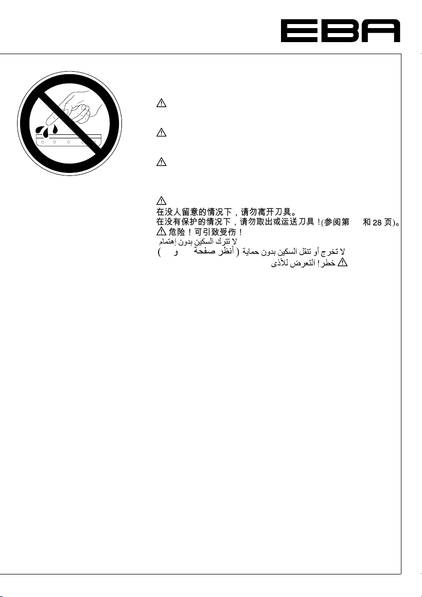
D Messer nie lose liegen lassen!
GB Never leave the blade unattended!
F Ne jamais laisser la lame sans protections!
NL Laat nooit de messen alleen achter.
E ¡No quitar la cuchilla sin prestar atención. No desmontar no
S Lämna aldrig maskinen obemannad. Ta inte ur eller
FIN Käsittele terää aina varoen. Älä siirrä tai kuljeta terää ilman
N La aldri kniven ligge ubeskyttet. Ta aldri ut kniven eller
PLNigdy nie pozostawiac nozy bez nadzoru.
RUSНе оставляйте открытое лезвие без присмотра! Не
HSoha ne hagyja a kést őrizetlenül! Ne vegye ki vagy ne szállítsa
TRBýçaðý hiçbir zaman gözetimsiz býrakmayýnýz!
Sicherheitshinweise • Safety precautions
•
Consignes de sécurité • Veiligheidsvoorschriften
•
Misure di Sicurezza • Normas de Seguridad
Säkerhetsföreskrifter •Turvallisuusohjeita • Sikkerhetsforskriftene
•
Środki bezpieczeństwa • Меры предосторожности
•
•
Messer nur mit Messerwechselvorrichtung oder im
Messertransportkasten befördern!
(Siehe Seite 26 und 28).
Warnung! Verletzungsgefahr!
Do not extract or transport the blade without protection!
(See page 26 and 28).
Danger! Risk of injury!
Elle ne doit être démontée qu’à l’ aide du dispositif de
changement de lame (cf. page 26 et 28), ou transportée dans
son étui en bois!
Danger! Risques de coupures!
Transporteer de messen niet zonder de houten bescherming
(zie pagina 26 en 28).
Waarschuwing! Opgelet voor ongevallen!
Non lasciare mai la lama incustodita. Non rimuovere o
trasportare la lama senza protezione. (Vedi pagina 26 e 28).
Attenzione! Rischio di infortunio!
transportar la cuchilla sin protección! (vérase pág. 26 y 28).
¡Advertencia! ¡Peligro de hacerse daño!
transportera kniven utan skydd. (se sid 26 och 28).
Skaderisk!
suojaa! (katso sivu 26 ja 28).
Loukkaantumisen vaara!
transporter den uten beskyttelse (Se side 26 og 28).
FARE! Muligheter for skade!
Nie wyciagac lub transportowac nozy bez oslon!
(zobacz strona 26 i 28).
Ryzyko skaleczenia sie!
пытайтесь извлечь или транспортировать лезвие без
специальных мер предосторожности!
(См. страницы 26 è 28).
Соблюдайте выше перечисленные правила для
избежания травм!
a kést védőtok nélkül!
(Lásd 26. és 2 8. oldal).
Veszély! Sérülésveszély!
Býçaðý muhafazasýz olarak yerinden çýkartmayýnýz veya
taþýmayýnýz! (Sayfa 26 ve 28’e bakýnýz).
Dikkat! Yaralanma riski!
- 4 -
•
•
•
•
•
Page 5
Sicherheitshinweise • Safety precautions
•
Consignes de sécurité • Veiligheidsvoorschriften
•
Misure di Sicurezza • Normas de Seguridad
•
Säkerhetsföreskrifter •Turvallisuusohjeita • Sikkerhetsforskriftene
•
Środki bezpieczeństwa • Меры предосторожности
•
•
•
•
•
DK Knivbladet må aldrig efterlades uden opsyn. Forsøg ikke at
afmontere eller transportere knivbladet uden beskyttelse!
(Se side 26 og 28).
FARE! Risiko for legemlig beskadigelse.
CZNikdy nenechávejte nůž bez krytu. Nikdy nevyjímejte nebo
neprepravujte nuz bez ochranného krytu (viz. strany 26 a 28).
Nebezpecí! Riskujete zranení.
P Deixar a faca sempre em local seguro! Não retirar ou
transportar a faca sem protecção! (Ver pág. 26 e 28).
Perigo! Risco de dano!
GR МЗН БЦЗНЕФЕ ФЗН ЛЕРЙДБ БНЕРЙФЗСЗФЗ! МЗН
БЛЛБЖЕФЕ ¹ МЕФБЦЕСЕФЕ ФЗН ЛЕРЙДБ ЧЩСЙУ
РСПЦХЛБОЗ (ДеЯфе учефйкЬ уфйт уелЯдет 26 & 28).
РСПУПЧЗ! КЙНДХНПУ ФСБХМБФЙУМПХ!
CHI
UAE
26
28
•
26
- 5 -
Page 6
23456789012345678
9
EBA 551-06 • EBA 551-06 LT
Sicherheitshinweise • Safety precautions
•
Consignes de sécurité • Veiligheidsvoorschriften
•
Misure di Sicurezza • Normas de Seguridad
Säkerhetsföreskrifter •Turvallisuusohjeita • Sikkerhetsforskriftene
•
Środki bezpieczeństwa • Меры предосторожности
•
•
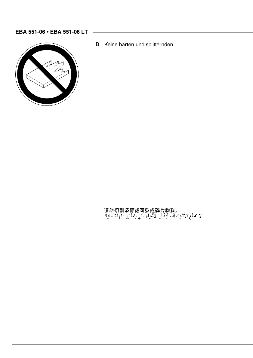
D Keine harten und splitternden Materialien schneiden!
GB Do not cut hard materials or materials which may splinter!
F La coupe de matériaux trop durs ou risquant des
projections est interdite!
NL Snij geen harde materialen of materiaal dat kan
splinteren!
I Utilizzare il tagliacarte esclusivamente per il taglio di
risme di carta o materiali analoghi!
E ¡No cortar materiales duros o materiales que puedan
astillarse!
S Förstör inte hârt material eller material som kan splittras!
FIN Asentakaa laite lasten ulottumattomiin!
N Ikke kutt hardt metall eller materiale som kan splintre!
PL Nie ciac twardych materialów lub materialów, które moga
ulec odprysnieciu!
RUS
Данный резак не предназначен для резки
твердых материалов или материалов, которые
могут расщепляться!
H Ne vágjon kemény vagy olyan anyagot, amely repedhet!
TR Sert veya parçalanabilecek malzemeleri kesmeyiniz!
DK Der må ikke skæres i hårde materialer eller i materialer,
der kan splintre!
CZ Neřežte tvrdý materiál, při kterém mohou ustřelovat ostré
úlomky!
P Não cortar materiais duros ou materiais que possam
lascar!
GR МЗН КПВЕФЕ УКЛЗСБ ХЛЙКБ ¹ ХЛЙКБ РПХ
ИСХММБФЙЖПНФБЙ!
CHI
UAE
•
•
•
•
•
- 6 -
Page 7
Safety precautions
•
•
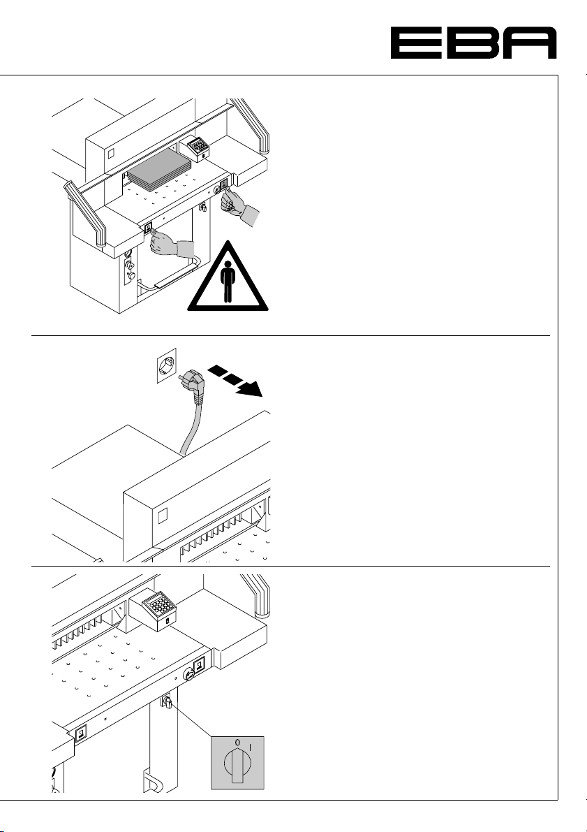
The machine is designed for cutting stacks of
paper to a specified size. This machine is
constructed for "one-man operation" only!
Disconnect from the mains before starting any
service work or before removing the panels!
Replacement of blade and cutting stick may
be performed only when the main switch is
switched off!
- 7 -
Page 8
2345678901234567
8
8
EBA 551-06 • EBA 551-06 LT
2345678901234567
Safety precautions
•
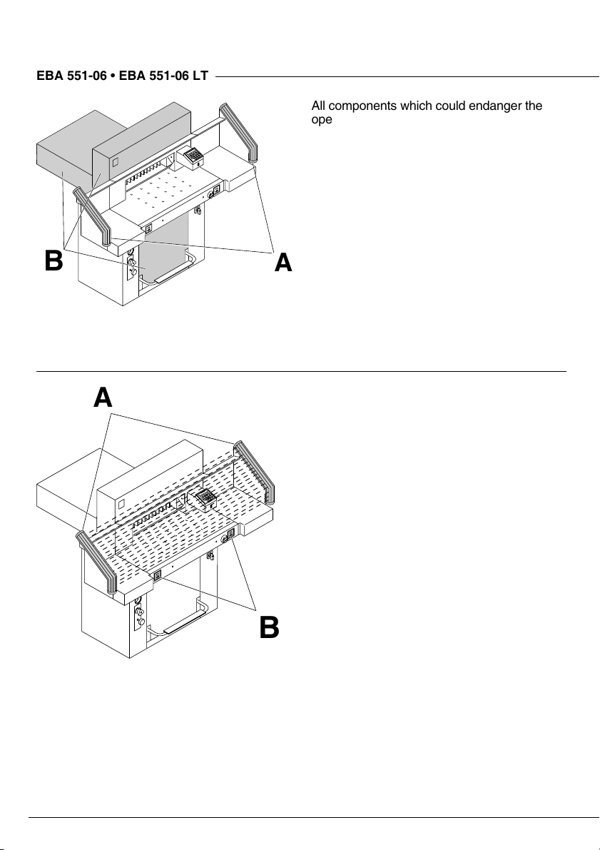
All components which could endanger the
operator are covered by a guard (B)!
Do not operate the machine without the
following safety devices:
Safety beam guard (A)
•
Panels, tightly screwed (B).
•
•
B
A
A
The cutting action, which is dangerous to the
operator, is protected by a two-handed control
system (C) and safety beam guard (D).
B
- 8 -
Page 9
Safety precautions
•
•
Protect mains cable against heat, oil and
sharp edges!
Standard machines are factory-set as follows:
Voltage 230 V (120 V) 1 phase
•
Frequency 50 Hz (60 Hz).
•
When not in use for a longer period switch off.
(Main switch to "0").
- 9 -
Page 10
2345678901234567
8
8
EBA 551-06 • EBA 551-06 LT
2345678901234567
B
A
C
B
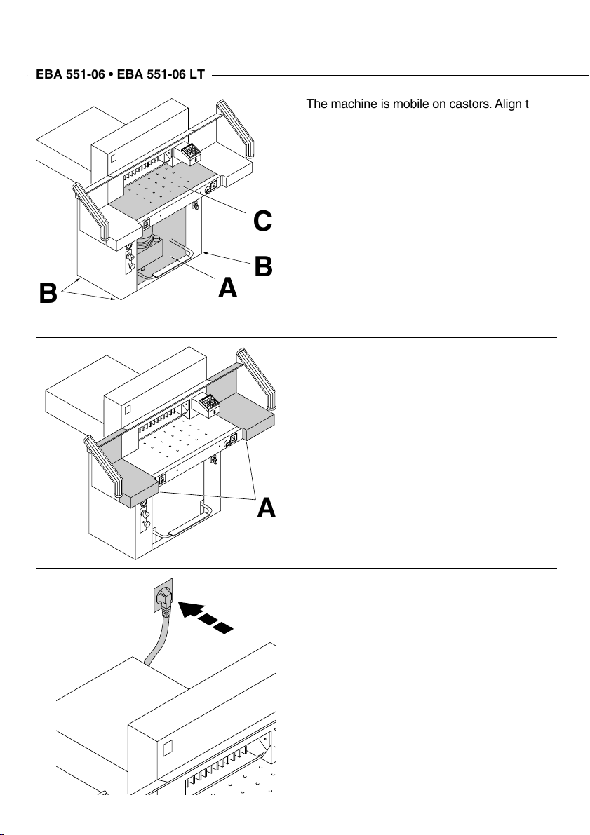
Installation
•
The machine is mobile on castors. Align the
machine as followes:
Remove cover (A).
•
Align machine with water level and adjust
•
accordingliy.
4 x screws size 19 4 x nuts (B)
Reference area machine table (C).
•
Replace cover (A).
•
The machine is delivered ready for operation.
Side tables (A), left and right are available as
an option. Assembly instructions are included.
•
A
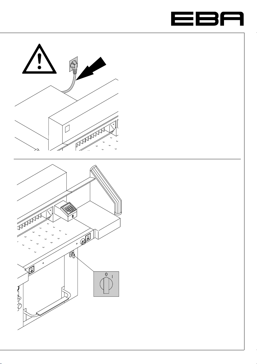
Plug into socket.
- 10 -
Page 11
Operation
•
A
•
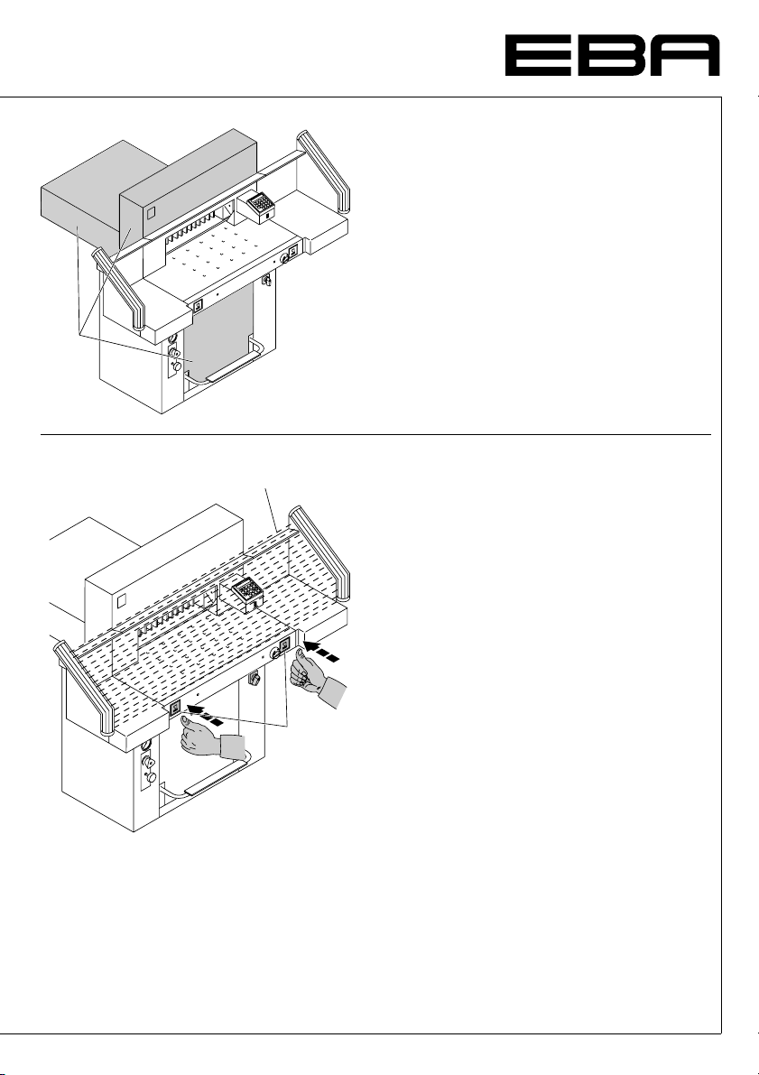
It is forbidden to operate the machine if the
operating and safety instructions have not
been understood. Please check the safety
devices are functioning and complete
before use.
All covers have to be mounted (A).
•
The release for cutting is allowed only if the
•
B
two-hand safety device is operated at the
same time (C).
The machine stops immediately if anyone
•
reaches into the cutting area (B).
We recommend you keep a record of your
test results.
C
- 11 -
Page 12
2345678901234567
8
8
EBA 551-06 • EBA 551-06 LT
2345678901234567
Operation
•
•
B
C
A
B
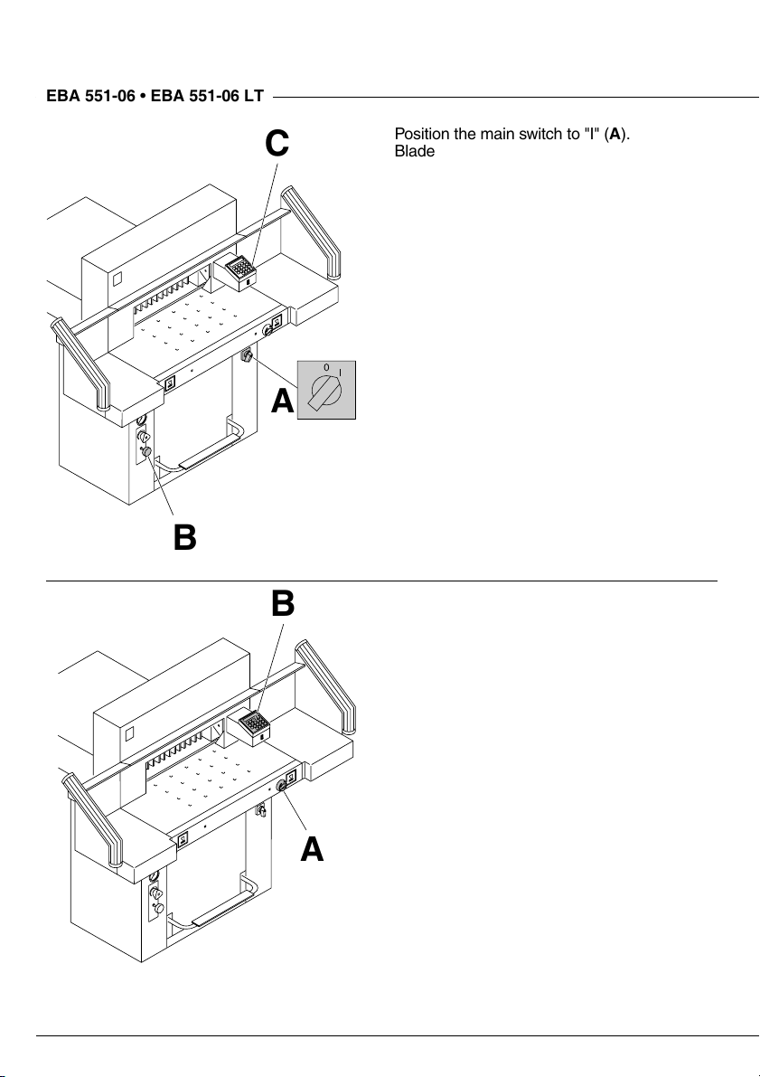
Position the main switch to "I" (A).
Blade locking facility (B) must be pulled out.
Press
automatically go to the start position.
The machine is now ready for use.
The measurement is set either with the
handwheel (A) or by programming (B) the
cutting measurements. Measurement is
shown on the display in inches or cm (B).
button (C). Machine will
S
A
- 12 -
Page 13
Operation
•
•
A
A
B
Optical cutting line indicator:
Optical cutting red line (A), indicates the
position of the cut. Blade cuts on the front
edge of the light beam.
Mechanical cutting line indicator:
The clamp (B) can be used as cutting line
indicator for cutting. Pre-clamping can be
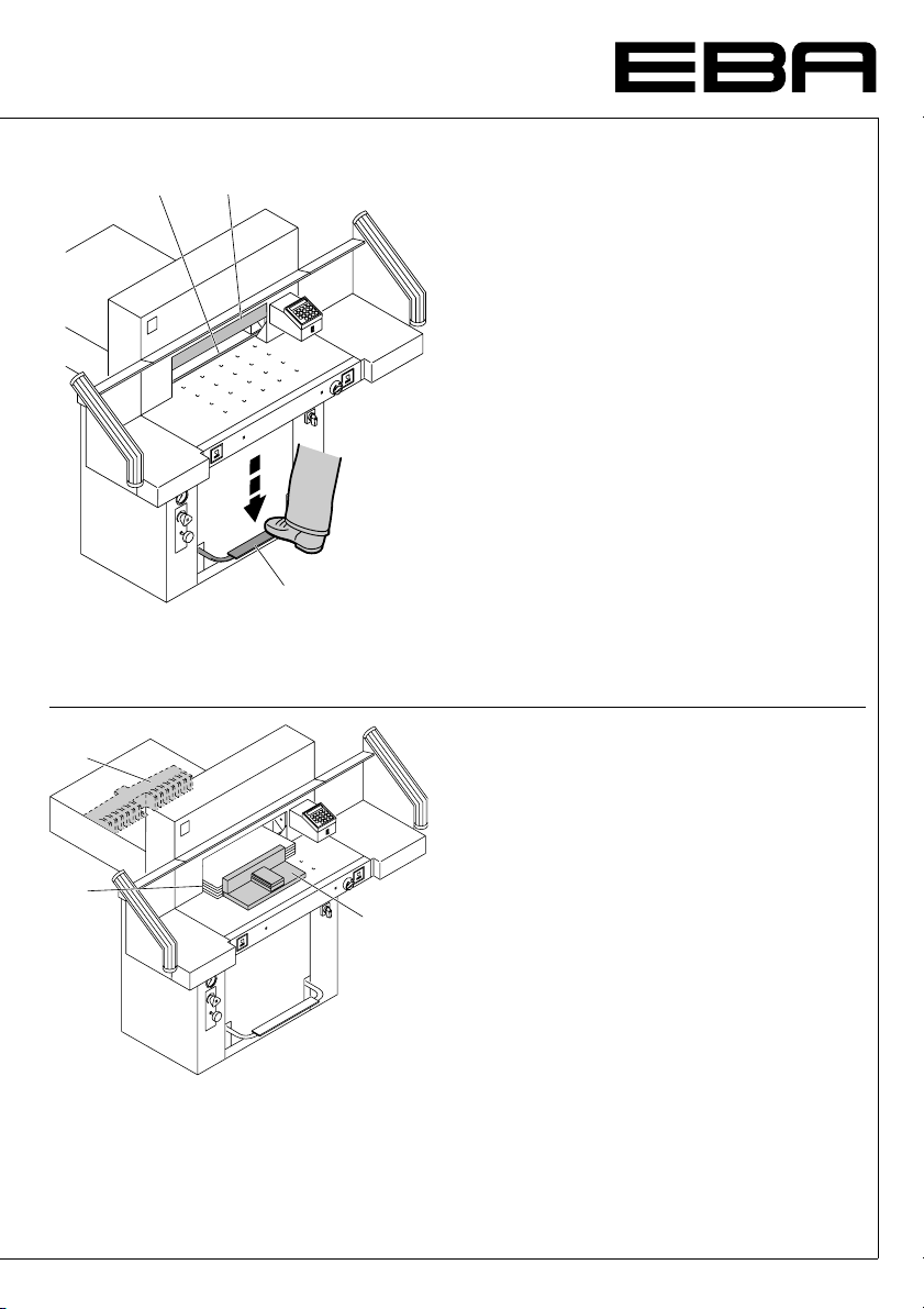
performed using the foot pedal (C).
Only use the optical cutting line indicator and
mechanical cutting line indicator when no
exact cut is required.
C
Position the paper on the backgauge (A) and
side lays left or right (B). To move paper
stacks, please use the paper knock-up block
(C) provided.
(Run backgauge to the front for turning the
paper stack).
B
C
- 13 -
Page 14
2345678901234567
8
8
A
B
EBA 551-06 • EBA 551-06 LT
2345678901234567
B
A
Operation
•
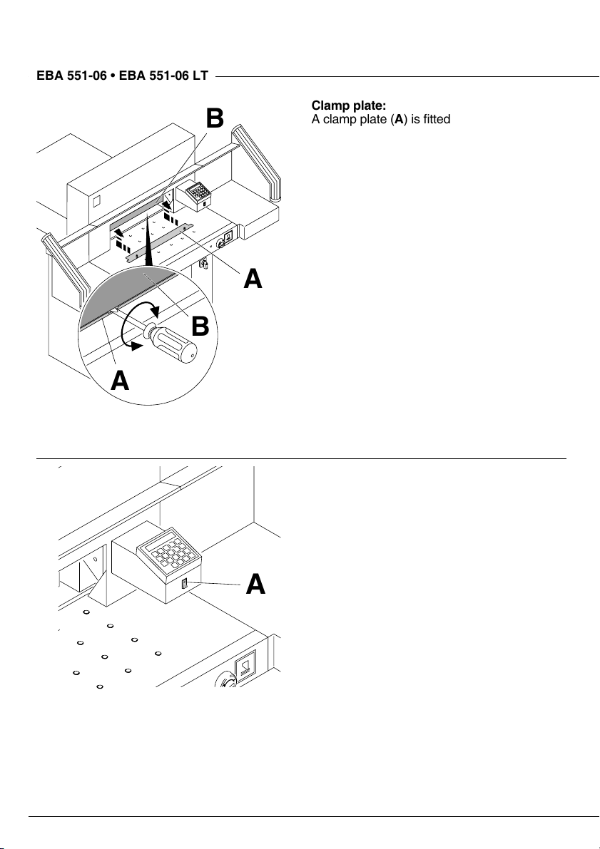
Clamp plate:
A clamp plate (A) is fitted to the machine to
prevent pressure marks on sensitive material.
To dismantle:
• Remove the clamp plate (A) by turning the
screwdriver (found in tool box) in the space
between the clamp and clamp plate.
© The remaining cut is 32 mm.
To mount:
• The clamp plate (A) is inserted to the top
into the clamp (B).
© The remaining cut is 60 mm.
•
Air table
It is easier to position large stacks of paper
when the airtable (A) is switched on.
A
- 14 -
Page 15

B
A
Operation
•
•
Setting clamping pressure
If necessary, set clamping pressure with
setting wheel (A). If a cutting process has
been activated, the oil pressure can be seen
on the oil pressure indicator (B).
A
The clamp moves automatically when cutting
is activated. The paper can be pressed in
advance, with the foot pedal (A). Cutting is
activated by pressing both buttons (B) on the
front table.
B
- 15 -
Page 16

2345678901234567
8
8
EBA 551-06 • EBA 551-06 LT
2345678901234567
A
B
Operation
•
Cutting activation
Do not reach into the cutting area when the
blade is in motion. A cut can only be activated
when the specified size is approached. The
LED "S" on the display must be deleted.
Release the photo-electric beam guard (A).
•
Press both buttons of the safety two-handed
•
control system (B) simultaneously and keep
them pressed until the paper is completely
cut.
•
Cutting stop or interruption:
Release both buttons of the two-hand
control (A).
A
- 16 -
Page 17

Operation
•
cm
inch
•
Operating elements
- Safety beam guard
A
- Safety two-handed control system
B
Pre-clamping and cutting
- Air table On-Off
C
- Backgauge control (EP)
D
- Foot pedal with clamp
E
- Main switch
F
- Hand-wheel for backgauge setting
G
- Blade locking
H
- Backgauge
I
- Side lay left and right
J
- Clamp pressure
K
- Clamp pressure adjustment
L
- Display cutting size (cm or inch)
M
- Select program step up
N
- Select program step down
O
- Stop and delete input
P
- Start
Q
- Memory multiple cut
R
- Keypad
S
T - Changeover cm - inch
- Clear program
U
- Select program
V
- Enter
W
- Program number
X
- Program step
Y
- Specified dimensions
Z
- Display multiple cut
a
- 17 -
Page 18

2345678901234567
8
8
cm
inch
EBA 551-06 • EBA 551-06 LT
2345678901234567
cm
inch
Operation
•
Start machine
• Main switch F to position "I", Pull out blade
locking key
• Press
to the rear and searches for the reference
position, wait until a measurement is shown
in the display
Warning!
Before storing or cutting a measurement
please check if the correct measurement
scale (cm or inch) see above is stored. For
information on how to store see picture
below left.
Cutting to specified dimensions
• Enter dimension on the numerical key pad
© LED "S" Z appears. (If a wrong
S
dimension is entered this can be corrected
by pressing the
• Press
approached, © LED "S" disappears.
Dimensions below 9 cm can only be
approached with the
held. (When the S button Q is released,
the backgauge
of 9 cm © measurement 9 cm appears,
keep the
moves to e.g. 7 cm).
• Insert paper and move by means of the
stacking angle to the backgauge
lay on the left
• Release the cut.
Cut according to markings
• Adjust the backgauge with the
hand-wheel
• Insert paper and move by means of the
stacking angle to the backgauge
side lay on the left
• Turn the hand-wheel G to the right until the
marking on the paper to be cut is below the
cutting line indicator.
• The further the hand-wheel
the right, the quicker the backgauge moves.
If the hand-wheel is turned to the left the
backgauge will return quicker.
• Release the cut.
.
H
button Q © backgauge I moves
S
(57 cm or 22,44 inches).
D
button).
s
button © dimension is
S
button pressed and
S
moves to a measurement
I
button pressed, backgauge
S
and side
.
J
to the back.
G
J
.
I
and
I
is turned to
G
I
•
- 18 -
Page 19

Operation
•
cm
inch
•
Eject function
If button r O is pressed instead of button
Q, after inserting the measurement, the
S
backgauge will advance forwards to
measurement 9 cm/3,54 inch (standard
setting of the machine) so that paper can be
removed. Finally the backgauge moves to the
last setting.
Adjust the eject-dimension
Press
•
© e on display.
Insert the desired dimension.
•
•
g
Multiple cut
Enter the multiple cut size on the display
•
Advance to the measurement with the
•
button.
Push the paper to the backgauge I.
•
Press
•
will be on.
Enter the multiple cut size.
•
After each cut the backgauge advances to
•
the next dimension automatically.
Pressing the
•
size.
, press T, Press p press
p
Store dimension.
button © the red LED "M " a light
T
button P shows the actual
s
T
S
S
.
Exiting program-mode
Press
•
on the display.
Cutting activation
Warning!
Run backgauge to the front for turning the
•
paper stack.
Do not interrupt the upward movement of
•
the blade by performing switching
procedures.
Release blade only when LED "S" has gone
•
out.
Blade must always be at the top and be
•
covered by the clamp. Do not touch the
blade.
- 19 -
button © LED "M " a is cleared
T
Risk of injury!
Page 20

2345678901234567
8
8
EBA 551-06 • EBA 551-06 LT
2345678901234567
cm
inch
A
Operation
•
Programming
This control system enables you to store 9
programs with 9 programmable steps. One
step represents one measurement. After
entering the program numbers you are able to
change between several program steps with
the button
First figure on display = program number.
Second figure = program step. Dimensions
below 9 cm can only be approached with the
button held pressed.
S
"
u" on the display © the entered dimension
is too low.
"
o" on the display © the entered dimension
is too high.
The indicated program step can be
overwritten at any time. These programs
remain stored when the machine is off.
Should you change to another dimension unit
all programmed measurements are converted
into the new unit (cm or inch).
Entering a program
Press
•
... 9 Enter program number 1...9.
•
1
(First figure on display = program number).
Enter dimension, or move the backgauge to
•
the desired measurement with the
hand-wheel (A).
Store the dimension © next program
•
g
step appears. If the hand-wheel (A) is used
to approach the cutting position press
button
Enter the next dimension.
•
(Should an ejection be desired before this
cut push the
simultaneously).
Should the entered program be required
•
immediately © press
closed).
Press
dimension of the first program).
Or:
+ S Escape the program mode.
•
p
and h.
r
© P appears on the display.
p
next program step appears.
h
button and r button
g
(program is
S
again (backgauge moves to the
S
•
- 20 -
Page 21

Operation
•
cm
inch
•
Eject function program
Set the measurement © push g button
•
and
simultaneously. e appears shortly
r
on the display. The backgauge will advance
and eject the paper and finally return to the
position shown on the display.
Programming of multiple cut dimension
Press © P appears on the display.
•
p
... 9 Enter program number 1 ... 9.
•
1
First figure on display = program number.
Second figure = program step.
Enter the cut size on the display
Store the dimension.
•
g
... 9 Enter multiple cut size.
•
1
© Press T button E and multiple cut size
appears on the display. Press
again
F and second
multiple cut size appears etc.
Store the dimension.
•
g
+ s Escape the program mode.
•
p
Maximum nine multiple cuts can be entered.
Entering the tenth multiple cut will delete the
multiple cut and the display will show the
actual program step.
Deleting a dimension when programming
Press
and overwrite the dimension.
s
T
.
S
button
Cancel a program
press © P appears on the display.
•
p
... 9 Enter program number 1...9.
•
1
Press button
•
Each program has to be cancelled separately.
Only single program steps can be overwritten.
Deleting the last program step
Enter
•
•
p
- 21 -
0
Press
g
+ s Escape the program mode.
twice.
c
.
.
Page 22

2345678901234567
8
8
cm
inch
EBA 551-06 • EBA 551-06 LT
2345678901234567
cm
inch
Operation
•
Working with programs
Press p © P appears on the display
•
... 9 Enter program number 1 ... 9.
•
1
With the button
change between several program steps. With
the backgauge moves to the indicated
S
dimension. With
General
LED "S" blinks © the basic position will
appear. LED "S" is off © the actual dimension
appears. In the program mode the ejection of
paper
paper has to be programmed.
After each cut the backgauge advances to the
next dimension automatically.
is not possible. The ejection of
r
and h you are able to
r
the backgauge stops.
s
•
Escape the program mode
Press
•
Press
•
Program buttons
Button
Button
Press p and simultaneously h (U appears
on the display) or Press
simultaneously
display)
Enter the desired dimension (For example:
•
29,7 cm x 42 cm can be entered for DIN A3)
•
g
Display in cm or inch
Press
inch (see picture left). Measurements (in cm
or inches) for the rear reference point of the
backgauge are shown on the top of page 18.
© P appears on the display.
p
© escape the program mode.
s
and r programs
= backgauge position rear
h
= backgauge position front
r
Store dimension.
© display changes between cm and
i
h
and
p
(D appears on the
r
- 22 -
Page 23

Blade and cutting stick replacement
•
•
If the cutting quality decreases:
• Check the cutting depth (see page 33).
• Check the cutting stick (see page 27).
• Replace or grind the blade
(see page 23 - 32).
The blade cannot be ground if the blade
height is less than 82 mm/3,23 inches.
A new blade must be used.
Blades may only be sharpened by
a specialist.
Danger! Risk of injury!
The blade is extremely sharp. Do not extract
or transport the blade without protection.
Changing the blade may only be performed
by trained staff.
- 23 -
Page 24

2345678901234567
8
8
A
EBA 551-06 • EBA 551-06 LT
2345678901234567
B
C
Blade and cutting stick replacement
•
Set mains switch (A) to position "I" .
•
Set clamping oil pressure (B) to min. 50 bar.
•
Press in blade locking key (C).
•
Activate cutting blade remains in lowest
•
position.
Set mains switch to position "0".
•
Remove the left screw (D), using the
extension.
•
D
Pull out blade locking key blade moves to
the top.
- 24 -
Page 25

Blade and cutting stick replacement
•
•
Remove both outer screws.
Mount blade changing tool (A).
A
B
Tighten screws (B).
- 25 -
Page 26

2345678901234567
8
8
EBA 551-06 • EBA 551-06 LT
2345678901234567
A
Blade and cutting stick replacement
•
Remove remaining two screws (A).
Simultaneously slightly loosen both screws
(B) and remove blade with blade
changing tool.
Weight of blade approx. 5 kg.
•
B
Place the blade into the blade carrier and
screw it into place.
- 26 -
Page 27

Blade and cutting stick replacement
•
B
A
•
Loosen screws (A) (SW4).
•
Remove cutting stick (B).
•
If needed the cutting stick can be turned or
•
exchanged.
Turn screw (C) as far as possible to the
•
right.
Slightly tighten screws (A).
•
The cutting stick can be used eight times.
Replacing the cutting stick (not the blade)
Loosen screws (A) (SW4).
•
Remove cutting stick (B).
•
Turn the cutting stick (the non-used side
•
must be near to the blade).
Turn screw (C) as far as possible to the right
•
(Otherwise the first cut will be too deep).
Slightly tighten screws (A).
•
Danger! Risk of injury!
C
Cutting test after replacing the cutting
stick (not the blade)
• Insert the paper and release the cut.
• If the last sheet of paper is not cut along the
entire length turn the blade adjusting
screw (C) 1/6 turn to the left.
• If the last sheet is still not completely cut
repeat this process until the last sheet is cut
along the entire length.
- 27 -
Page 28

2345678901234567
8
8
EBA 551-06 • EBA 551-06 LT
2345678901234567
AB
C
D
E
E
D
Blade and cutting stick replacement
•
Take the exchange blade carefully out of the
blade box and screw it to the blade changing
tool (D).
Check, if when using the upper threads (B),
•
the blade (E) is protected.
The blade is not protected Use the lower
•
thread (C) for fixing. The screws (A) may not
exceed at the rear side of the blade.
Danger!
Blade (E) must be protected.
Mount the blade with the blade changing
tool (A) ...
•
B
A
... and tighten with screws (B) in upper
position.
Blade must be in the upper position.
- 28 -
Page 29

Blade and cutting stick replacement
•
•
Screw in middle screws and tighten.
Remove the blade changing tool.
Slightly screw in outer screws.
- 29 -
Page 30

2345678901234567
8
8
1.
2.
EBA 551-06 • EBA 551-06 LT
2345678901234567
1.
2.
1.
Blade and cutting stick replacement
•
Press in blade locking key.
•
Set main switch to position "I".
•
Activate cutting blade remains in the
•
lowest position.
Set main switch to position "0".
•
•
Screw in slightly the left screw.
- 30 -
Page 31

Blade and cutting stick replacement
•
A
B
•
Loosen slightly screws (A) so that the blade
slides onto the cutting stick.
Push the blade and screw (B) as far as
possible to the left or right and then centralize
them. The blade must rest on the cutting
stick.
1.
Push in the first screw on the left side
and tighten.
- 31 -
Page 32

2345678901234567
8
8
EBA 551-06 • EBA 551-06 LT
2345678901234567
4.
3.
2.
Blade and cutting stick replacement
•
Tighten the remaining 3 screws beginning
from the left.
Pull out blade locking key blade moves to
the top.
•
5.
Tighten the screw which is visible at the right.
- 32 -
Page 33

Blade and cutting stick replacement
•
A
•
Turn main switch to position "I".
A
Paper cutting test. If the last sheet or several
sheets are not completely cut, gradually turn
the knob for blade depth adjustment (A)
1/6 turn to the left until the paper is cut along
the entire length. Do not set too low as blade
will soon become blunt.
- 33 -
Page 34

2345678901234567
8
8
EBA 551-06 • EBA 551-06 LT
2345678901234567
A
B
Maintenance and cleaning
•
Maintenance work may only be performed by
trained staff.
Danger!
Disconnect the mains before starting any
service work or before removing the
cover.
Grease and oil the machine according to the
lubrication diagram after 1000 operating
hours or once a year. If the machine is subject
to excessive load then twice a year.
The hydraulic oil must be changed every 2000
operating hours or every 2 years.
Type of oil:
Aral Vitam DE 46 to DIN 51562.
Volume: approximately 7 litres.
(A) Drain screw
(B) Oil stick
Check that the hydraulic pump and screws
•
are not leaking. If necessary tighten the
retaining nut.
Check pressure. Maximum pressure
•
is 150 bar.
•
- 34 -
Page 35

10
11
13
14
12
15
Maintenance and cleaning
•
•
11
16
1
Lubrication schedule
Lubricate (1) to (8).
Type of oil: SAE10 to SAE50 all types.
Grease (9) to (16)
(9+10) Blade guidance
9
10
(11-12) Clamp guidance
Type of grease:
Roller bearing grease - all types.
Oil hinges of the foot clamping device at the
front area of the machine room.
Type of oil: SAE10 to SAE50 all types.
4
3
2
1
5
6
7
8
12
15
14
2011
13
Safety test
The safety regulations are according to the
regulations of the country where the cutting
machine is operated. The manufacturer
recommends a safety check is made every
5 years by an authorised service team.
- 35 -
Page 36

2345678901234567
8
8
EBA 551-06 • EBA 551-06 LT
2345678901234567
Possible malfunctions
•
Machine does not function!
Is the machine plugged in?
•
Main switch to position "I"? (A)
•
Blade locking facility (B) must be pulled out.
•
Push in the fuses in the back of the machine
•
F1, F2, F3.
Check the units fuse and the on-site circuit
•
breaker.
A
B
- 36 -
Page 37

B
A
Possible malfunctions
•
cm
inch
•
Cut cannot be made.
• Measurement has not been reached
correctly. LED "S" does not turn off.
Push the
• Measurement below 9 cm.
Hold the
measurement is achieved.
Oil pressure set too low. Increase oil
•
pressure at rotary control (A).
Hydraulic oil shortage. Check hydraulic
•
oil level (B), if necessary, top up.
button again.
S
button until the
S
Backgauge not in the right position,
•
"
C" on display. Contact your dealer.
- 37 -
Page 38

2345678901234567
8
8
EBA 551-06 • EBA 551-06 LT
2345678901234567
A
Possible malfunctions
•
Does not cut through the last sheet.
Reset the cutting depth (A) ...
... or turn / replace the cutting stick (B). (See
page 27 "Blade and cutting stick
replacement").
A reduction in the cutting quality indicates that
the blade must be sharpened or a blade
change is necessary.
•
- 38 -
Page 39

Possible malfunctions
•
•
Sender Receiver
A
D
C
B
D
Trouble shooting-light beam
• During normal operation the LED (A) must
iluminate orange and LED (B) green.
• Display (C) is permanently on orange when
the sender and/or receiver require cleaning.
Clean the glass (D) from the sender and
receiver.
EBA
"Service"
None of the above mentioned methods
helped to solve the problem:
Contact Service Team under
www.eba.de © "Service"
•
service@krug-priester.com.
- 39 -
Page 40

2345678901234567
8
8
EBA 551-06 • EBA 551-06 LT
2345678901234567
Recommended accessories
HSS - Blade
4 244 4 036
•
6 Cutting sticks
4 244 1 209
•
Accessories
•
•
Blade changing tool
3 244 0 024
•
Paper knock-up block
9000 521
•
1
1
Side tables left and right
3 245 7 027
•
1
Included in delivery.
- 40 -
Page 41

Technical Data
•
A
•
Technical Data
Power supply: 230 V / 50 Hz / 8,5A / 1~
120 V / 60 Hz / 12A / 1~
Cutting length: 550 mm
Cutting height: 95 mm
Table depth: 570 mm
Sound level EN 13023: < 70 dB(A)
Minimum space requirement
(width x depth x height)
without side tables (mm) 1070 x 1400 x 1370
with side tables (mm) 1630 x 1400 x 1370
Clamping pressure 200 daN bis 1100 daN
Weight without side tables: 305 kg
Capacity of hydraulic oil: 7 l
Aral Vitam DE 46 to DIN 51562.
Used oil must be disposed of at the authorised
place.
Ambient operating temperature 10 °C - 60 °C
Air humidity (not condensating) 15 % - 95 %
The exact technical specifications can be found
on the technical specifications sticker (A) on the
machine. To claim under guarantee, the machine
must still carry its original identification label.
A wiring diagram is found in the electrical switch
box.
Safety beam guard
Total reaction time: 100 ms
•
Resolution 14 mm/minimum distance: 268 mm
•
Resolution 20 mm/minimum distance: 308 mm
•
Resolution 30 mm/minimum distance: 388 mm
•
Subject to alteration without notice.
- 41 -
Page 42

Übersetzungen siehe 550 2006-09
8
8
2345678901234567
EBA 551-06 • EBA 551-06 LT
2345678901234567
- 42 -
Page 43

D EG-KONFORMITÄTSERKLÄRUNG
GB EC-declaration of conformity
F Déclaration de conformité CE
NL EG-verklaring van overeenstemming
I Dichiarazione CE di conformità
E Declaración CE de conformidad
S EG-försäkran om överensstämmelse
- Hiermit erklären wir, daß die Bauart von
- Herewith we declare that
- Par la présente, nous déclarons que
- Hiermede verklaren wij, dat de in de handel gebrachte machine
- Si dichiara che il modello della
- Por la presente, declaramos que la
- Härmed förklarar vi att den av oss levererade typen av
551-06; 551-06 LT
- folgenden einschlägigen Bestimmungen entspricht
- complies with the following provisons applying to it
- sont conformes aux dispositions pertinentes suivantes
- voldoet aan de eisen van de in het vervolg genoemde bepalingen
- è conforme alle seguenti disposizioni pertinenti
- satisface las disposiciones pertinentes siguientes
- uppfyller följande tillämpliga bestämmelser
98/37/EG; 2006/95/EG; 2004/108/EG
- Angewendete harmonisierte Normen insbesondere
- Applied harmonised standards in particular
- Normes harmonisées utilisées, notamment
- Gebruikte geharmoniseerde normen, in het bijzondere
- Norme armonizzate applicate in particolare
- Normas armonizadas utilizadas particularmente
- Tillämpade standarder, speciellt
EN 60204-1; EN 1010-1; EN 1010-3; EN 55014-1; EN 55014-2;
EN 61000-3-2; EN 61000-3-3; EN 61496-1; prEN 61496-2;
EN ISO 12100-1; EN ISO 12100-2; EN 294; EN 954-1; EN 13023
Krug & Priester GmbH u. Co KG 23. 04 . 2007
72336 Balingen, Germany Datum Wolfgang Priester
- General Manager -
- 43 -
Page 44

23456789012
3
5
2345678901234
EBA • Made in Germany
EBA 5140 S/C/CC/CCC
Aktenvernichter
Document Shredders
Destructeurs de Documents
Papiervernietigers
Distruggidocumenti
Destructoras de Documentos
Dokumentförstörare
Dokumentförstörare
Schneidemaschinen
Guillotines
Massicots
Snijmachines
Tagliacarte
Guillotinas
SkärmaskinerSkärmaskiner
EBA Krug & Priester • 72336 Balingen • Germany • www.eba.de
•
- 24 -
Printed in Germany 09/2006
•
 Loading...