

Page 1

Trimmer
OPERATION
MANUAL
Trimmer
Page 2

Trimmer
CONTENTS
Introduction........................................................ 3
Specifications ..................................................... 3
Safety ................................................................. 4, 5
Installation .......................................................... 6-8
Setup .................................................................. 9
Control Panel ..................................................... 10
Operation ........................................................... 11, 12
Maintenance ....................................................... 13
Adjustments ....................................................... 14
Fuses Access ...................................................... 15
Preventive Maintenance ..................................... 15
Knife Removal & Installation ......................... 16-19
Clearing A Trimming Jam ............................... 19
Knife Care Tips ................................................. 20
Notes .................................................................. 21
Trouble Shooting ............................................... 22-25
2
Page 3

INTRODUCTION
MBM Corporation is proud to introduce another addition to its complete line of equipment for bookletmaking.
Now you have the ability to trim books in-line! This combination offers you reliability and versatility that
improves production and reduces downtime.
Trimmer Features:
In-line face trimming of booklets
Jam detection
Electrical interface for communication with StitchFold Bookletmaking System
Safety interlock
See-through top cover
TRIMMER SPECIFICATIONS
Unit Weight: 236 Pounds
Speed: Up to 2,400 booklets per hour (115Vac machine)
Capacity: Minimum
4.00" cut width x 4.13" to fold (trim length)
2 sheets 20# bond thickness
Maximum
12.71" cut width x 9.00" to fold (trim length)
50 sheets 20# bond thickness (0.20")
.625" maximum material trim
Booklets: 4.25" x 5.5", 5.5" x 8.5", 8.5" x 11", 4.75" x 4.75 "CD", & metric sizes
(All booklets with or without trim stock on one or three sides)
Output: Indexing conveyor
Footprint: 16.50" x 18.38"
Dimensions: Height 27.38" Width 26.42" Length without discharge table 25.90"
Length with fully extended discharge table 48.44"
Modes: Trim or No-trim
Electrical: Standard outlet - 115 Volts, 60 Hz, 6 Amps (1/4 HP)
Optional: 230Vac, 50 Hz, 3 Amps
3
Page 4

Trimmer
SAFETY PRECAUTIONS AND PROCEDURES
1. Make sure electrical power is turned off before performing any adjustment or maintenance.
2. Keep hands, hair, tools, and clothing clear of
trimming area.
SAFETY
5.
6.
NEVER REACH UNDER THE KNIFE Severe
lacerations or dismemberment could result.
NEVER OPERATE THE TRIMMER WITHOUT
THE B2000 BOOKLETMAKER AND SAFETY
INTERLOCK SYSTEM.
3. Become familiar with the moving components
of your machine. Keep fingers away from
areas that could pinch or cut.
BE EXTREMELY CAREFUL when changing
4.
the cutter knife. Severe lacerations or dismemberment could result from careless handling procedures.
6. A well maintained machine is a safer machine.
Clean and lubricate the machine at regular intervals. Check machine daily for broken or
worn parts. Replace as necessary. DO NOT
attempt to operate the machine if a part is broken.
7. See "SAFETY GUARDS" below! If you are
unsure how to safely operate your trimmer, contact
your Service Representative.
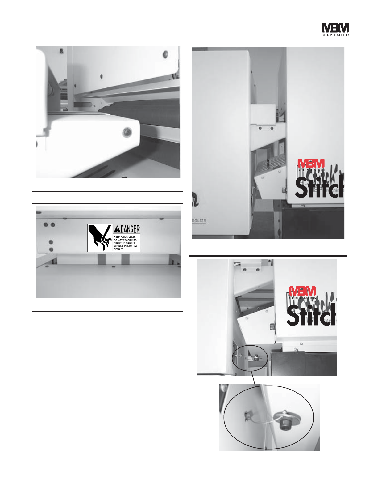
DANGER
KEEP HANDS CLEAR OF TRIMMING AREA AND ANY MOVING PARTS!
NEVER OPERATE MACHINE WITHOUT ALL GUARDS IN PLACE!
SAFETY GUARDS (figs 1 & 2)
A. Top Cover: Blocks access to mechanism that
drives the trimming knife and conveyor belts.
An electrical interlock keeps the machine
turned off unless this guard is closed. Do not
stick your fingers under the top guard!
B. Front Upper Cover: Blocks access to the trim-
ming knives and the mechanism that drives the
upper trimming knife.
C. Infeed Table Bottom Cover: Blocks access to
infeed conveyor belts.
D. Front Lower Cover: Blocks access to danger-
ous electric voltage and mechanisms that can
pinch or cut. Be sure to disconnect electrical
power before removing this cover.
4
E. Right Side Cover: Blocks access to low volt-
age connections and mechanisms that can pinch
or cut. Do not stick your fingers beyond this
cover!
F. Rear Upper Cover: Blocks access to danger-
ous electric voltage and control circuit connections. Be sure to disconnect electrical
power before removing this cover.
G. Rear Lower Cover: Blocks access to low volt-
age connections and mechanisms that can pinch
or cut. Do not stick your fingers beyond this
cover!
H. Left Side Cover: Blocks access to low volt-
age connections and mechanisms that can pinch
or cut. Do not stick your fingers beyond this
cover!
Page 5

A. Top Cover
B Front Upper
Cover
Infeed Table
C.
Bottom
Cover
D.
Front Lower
Cover
SAFETY GUARDS
E. Right Side
Cover
F. Rear Upper
Cover
G. Rear Lower
Cover
(Fig 1)
H. Left Side
Cover
(Fig 2)
5
Page 6

Trimmer
INSTALLATION
BEFORE UNCRATING:
Examine the crate for visible damage. If the crate
is damaged, the machine might be damaged. Notify
the carrier who delivered the machine.
UNCRATING THE MACHINE:
Carefully remove the machine from its container.
Lift the machine by grasping its strong framework.
Tugging on cables, covers, or other delicate components could cause damage.
Examine the machine for damages incurred during
shipping. Do not install a damaged machine.
Notify the carrier immediately, and be sure to get
a signed copy of the Carrier Inspector's Report of
the damage incurred. Your service representative
will assist you in determining the cost of repairs.
CB145A Nut
CB379 Screw
RTM1327A Key
Back Cover
of Bookletmaker
(Fig 3)
ELECTRICAL POWER:
The power cord can be plugged into any 115V, 60
Hz, 1 Phase, 15 Amp circuit. The machine draws
less than 6 amps.
SAFETY INTERLOCK SYSTEM:
WARNING
NEVER OPERATE THE TRIMMER
WITHOUT THE B2000
BOOKLETMAKER AND SAFETY
INTERLOCK SYSTEM CONNECTED.
Connect the safety interlock system as follows:
1. Remove the back cover (see fig 3) from the
Bookletmaker.
2. Put the bolt through the washer of the safety
key assembly and screw the bolt half way into
the back cover of the Bookletmaker (see fig 4).
3. Install and securely tighten the nut onto the end
of the bolt (see fig 5). The bolt must only be
removeable by removing the nut first.
4. Install the back cover onto the Bookletmaker
(see fig 5).
6
(Fig 4)
(Fig 5)
Page 7
(Fig 6)
(Fig 7)
TRIMMER TO BOOKLETMAKER CONNECTIONS:
1. Adjust the height of the trimmer so that the top
of the trimmer infeed table is about even with
the middle of the BookletMakers top discharge
roller (see fig 6).
2. Position the trimmer behind the BookletMaker
so that the trimmer's infeed table is centered
with the BookletMakers discharge, and slightly
away from the BookletMaker's top discharge
roller (see figs. 7&8).
3. Install the safety interlock key that is hanging
from the bottom of the back cover (see fig 9).
(Fig 8)
(Fig 9)
7
Page 8
Trimmer
(Fig 10) (Fig 11)
DISCHARGE CONVEYOR TABLE:
Install discharge conveyor table per illustrations
(figs 10, 11, & 12).
(Fig 12)
8
Page 9

SETUP
(Fig 13)
TRIMMER HEIGHT:
The height of the trimmer can be adjusted up or
down slightly by use of the threaded adjustable
casters and locking nuts on the bottom of the trimmer or trimmer stand (fig 13).
ward to the desired location. There is a pointer
on the side of the back stop assembly that points
to a trim length scale installed on the inside wall
of the trimmer. Once located in the desired
position tighten the two thumb screws.
(Fig 14)
TRIM LENGTH:
To set the back stop assembly for the desired trim
length, loosen the two thumb screws (fig 14) and
slide the back stop assembly forward or back-
(Fig 15)
DISCHARGE TABLE ROLLERS:
Set the discharge table rollers forward for small
booklets or backward for large booklets. To adjust
the rollers, loosen thumb screws (fig 15), move
roller brackets to desired location, then retighten
thumb screws.
9
Page 10

Trimmer
F E D C B A
CONTROL PANEL (figs. 16 & 17)
(Fig 16)
A. Power On/Off: Green rocker switch turns on
or off power to the machine. Pilot light in
switch glows when power is on.
B. Start/Reset: Black rocker switch energizes
control circuit, which turns on motor. In
addition, the discharge conveyor will run and
the work gate will be raised as long as the
switch is depressed.
Note: Opening the top guard shuts off the
machine. It must be restarted as above.
C. Emergency Stop: Cuts off power to the
machine's drive and control circuit when
depressed. The Emergency Stop botton locks
in the down (off) position until manually turned
allowing it to pop back up into the power on
position. Restart machine per B above.
D. Trimming On/Off: Selector switch chooses
mode of operation: "On" for trimming jobs or
"Off" to allow work to pass through without
trimming.
F. Paper Jam When Lit: Glows to indicate that
there is a paper jam.
G. Belt Drive: Rotary switch controls when the
work conveyor belts shut off after incoming
work is sensed. The choice range is 1 through
6. "1" for quick shut off to "6" for maximum
extended running of the work conveyor belts
after incoming work is sensed.
E. Knife Change: Black rocker cycles the
trimming knife up and down as long as it is
depressed.
10
G
(Fig 17)
(SK891C Scene 1)
Page 11

OPERATION
STARTUP:
1. The "BELT DRIVE" rotary switch should be
set to "1" position.
2. Depress "POWER ON" switch to turn on
power.
3. Depress "START/RESET" switch to energize
control cicuit. The electric motor will now
energize and begin the infeed and internal conveyors.
4. Select "TRIMMING ON". Run the
Bookletmaker so that a booklet is deposited on
the trimmer's infeed table. The booklet will be
transported into the trimmer, trimmed, and ejected
onto the output conveyor. The output conveyor
runs for a short duration each time a booklet is
sensed entering the trimmer. This ensures that
there is no gap between work on the discharge
table.
NORMAL OPERATION:
1. Work is deposited, from the Bookletmaker, onto
the trimmer's infeed conveyor table.
2. The infeed conveyor belts pull the work into
the trimmer.
3. As the work is pulled into the trimmer, the
work passes above photo sensor number one,
located at the end of the infeed conveyor table.
Number one photo sensor recognizes the work
and tells the control circuit that work is entering the machine.
4. The infeed conveyor throws the work over the
lower knife area and into the middle work
conveyor belts.
5. The middle work conveyour belts pull the work
over photo sensor number two, located near
the work back stop gate. Number two photo
sensor recognizes the work and tells the control circuit that work has entered the trimming
area.
6. The control circuit then lets the conveyor belts
continue to run, for a short period of time, to
allow the work to run into and square up
against the back stop gate. The conveyor belts
are then stopped.
7. At this time the control circuit energizes the
trimming clutch solenoid, which releases the
trimming clutch to begin the trimming cycle.
8. The knife bar assembly begins to cycle downward.
9. As the knife bar assembly cycles downward
the gate clamp begins to squeeze, flatten, and
hold the leading end (or fold) of the work.
The front clamp then begins to squeeze, flatten, and hold the trim end of the work.
10. As the knife bar assembly continues downward the knive begins to cut/trim the work.
11. The knife bar then begins cycling back up to
the top of it's stroke (starting position).
12. As the knife bar approaches the top of it's
stroke, it passes the knife bar proximity sensor. The proximity sensor tells the control
circuit that the knife bar has reached the top of
it's stroke.
13. The control circuit then denergizes the trimming clutch solenoid which stops/ends the trimming cyle.
14. The control cicuit then energizes the gate solenoid, which lifts up the gate, and energizes
the infeed and middle conveyor belts.
15. The trimmed work is then conveyed out of the
trimmer and deposited on the discharge table.
16. When the next work to be trimmed is sensed
by number one photo sensor (on infeed table)
the control circuit energizes the discharge table
clutch for a short time. While the discharge
clutch is energized it runs the discharge table
conveyor belts. The belts move the work on
the discharge table a short distance. The control circuit then cuts power to the discharge
table clutch. The discharge table conveyor
belts and work stop moving until the next piece
of work to be trimmed causes the discharge
table cycle to repeat.
JAM DETECTION:
If the work does not finish passing over number
one photo sensor, within normal operating time,
the control circuit recognizes this as a jam. The
trimmer drive shuts off. The "PAPER JAM
WHEN LIT" indicator light becomes lit. A normally closed relay in the control panel (used as
the jam output to another machine or device)
closes.
11
Page 12

Trimmer
DANGER
NEVER REACH UNDER THE
KNIFE! SEVERE LACERATIONS
OR DISMEMBERMENT COULD
RESULT!
JAM CLEARING & RESTART:
1. Turn off power to the trimmer.
2. Remove work jam. DO NOT REACH UN-
DER THE KNIFE! SEVERE LACERATIONS OR DISMEMBERMENT COULD
RESULT.
3. Close all safety covers.
4. Depress "POWER ON" switch to turn on
power.
3. Depress "START/RESET" switch to energize
control cicuit. The electric motor and conveyor clutches will energize so trimming may
resume.
JAM OUTPUT:
(SK891C Scene 1)
(Fig 19)
BELT DRIVE:
The purpose of the "BELT DRIVE" rotary switch
(fig 19) is to make sure the work will square up
against the back stop to provide a good square cut
booklet.
When a jam occurs a normally closed relay in the
control panel closes. This relay is connected to
a .141" diameter female phone jack outlet (fig 18)
located on the power cord bracket. Any device
plugged into the phone jack will receive a closed
circuit signal, which that device can use to shut
down any upstream machines feeding work to the
trimmer.
(Fig 18)
12
The "1" setting means that the internal conveyor
belts will shut off quickly after the work is sensed
allowing time for the work to square up against
the back stop.
If the work does not square up fully against the
back stop before being trimmed, rotate the switch
to postition "2". This position allows the internal
conveyor belts to run for an additional short period of time (after the work is sensed) so that the
work will square up before being trimmed.
Positions "3" through "6" allow for progressively
longer conveyor belt running time for unusual work,
such as work that may slip on the conveyor belts,
to square up against the back stop.
Page 13

MAINTENANCE
The instructions on the following
pages are for the use of trained
personnel only!
Attempting to perform repair and
replacement procedures without
proper training may cause
machine damage or operator
injury!
13
Page 14

Trimmer
ADJUSTMENTS
(Fig 21)
(Fig 20)
KNIFE BAR SENSOR ADJUSTMENT:
The knife bar must always stop at the top of it's
stroke in order for work to enter the trimmer. If
the knife bar stops too low work will not be able
to get past the front clamp and/or knife, and work
jams will result.
The function of the knife bar sensor is to signal the
control circuit when the knife bar has reached the
top of it's stroke so that the control circuit can
denergize the trimming clutch causing the knife
bar to stop at the top of it's stroke.
1. With power on and drive motor running, use
the knife change toggle switch to jog the knife
bar to the top of it's stroke. If you can not
stop the knife bar at exactly the top of it's
stroke, it is better to stop it slightly before top
of stroke rather than after top of stroke.
2. Turn off and unplug power.
3. Remove the left cover.
4. Loosen the screws of the knife bar sensor,
move the sensor so that the top of the sensor
is even with the top of the knife bar (fig 20).
5. Reinstall the left cover.
BACK STOP GATE ADJUSTMENT:
The function of the back stop gate is to provide a
surface for the work to square up against so that
the knife will cut the work squarely. The back
stop gate must be parallel to the bottom knife.
1. Run several pieces of work through the trim
cycle.
2. By looking at the work, determine how much
one side or the other of the back stop gate
must be moved forward or backward.
3. Turn off and unplug power.
4. Remove rear discharge table.
5. Remove rear upper cover.
6. Open top cover.
7. Slide backgage carriage to front of machine.
8. Using a 3/8" box wrench and a 1/8" hex
wrench loosen and shift one of the shoulder
screws (fig 21) locating the back stop gate
(which will also shift the back stop gate)
forward or backward the amount needed to
square up the trim. Note: It may be necessary
to first move one shoulder screw and then the
other in order to obtain the maximum amount
of adjustment.
9. Reinstall lower cover and discharge table.
14
Page 15

(Fig 22)
FUSE ACCESS
Turn power off and unplug the machine. Remove
the rear upper cover (removal of four screws
required) above the work discharge area of the
machine. There are two fuse holders mounted on
the din rail. To access the fuses, pull out the fuse
compartment (fig 22) of each fuse holder and remove the fuses.
A. Motor Fuse: Fuse protects the motor input lines
of the machine. If this fuse fails, the motor
will not run. Replace with 6 amp fuse
#RTM1303F for 115Vac machine or 3 amp fuse
#RTM1330F for 230Vac machine.
B. Control Circuit Fuse: Fuse protects transformer.
If this fuse fails, none of the 24VDC components will operate. Replace with 1 amp fuse
#RTM1302F for 115Vac machine or 0.5 amp
fuse #RTM1329F for 230Vac machine.
PREVENTATIVE MAINTENANCE
LUBRICATION:
Disconnect electrical power. Next, remove the
front cover and both side covers.
Use SAE-20 oil to lubricate porous bronze bearings, plastic bearings, chains, shafts, and cutter
bar linkages.
CLEANING:
Use alcohol to clean the belts.
HARDWARE:
Remove the covers to check all nuts and bolts for
tightness. Loose hardware is the cause of most
component wear and in the electrical area could
cause short circuits and/or shock.
15
Page 16

Trimmer
KNIFE REMOVAL & INSTALLATION
(Fig 24)
(Fig 23)
UPPER KNIFE REMOVAL & INSTALLATION:
CAUTION: Changing knives can be very dangerous unless safety precautions are observed
and extreme care is taken when handling
knives
Keep handling of unprotected knives to
an absolute minimum.
Warn people of any unprotected knife.
Knife changing is a ONE PERSON OPERATION. Having more than one person trying to change knives invites accidents.
1. Use the "Knife Change" rocker switch to move
the knife bar to the bottom of it's stroke.
2. Turn off power and unplug power cord.
3. Remove bottom cover of infeed table.
4. Remove front upper cover and the lower bar
that the front upper cover attaches to.
5. Remove the left and right side covers.
6. Remove the four screws and nuts holding the
top infeed table's conveyor bracket to the infeed
table.
16
(Fig 25)
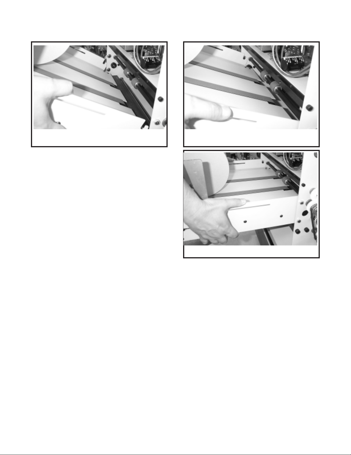
7. Carefully lift the right side of the upper infeed
conveyor bracket off the infeed table. Swing
it out and lay it on the infeed table (fig 23).
NOTE: Be sure the round belt does not come
off pulleys and be sure the separating finger
stays between belts where they cross or the
infeed table conveyors wil not operate properly when reassembled.
8. Loosen, BUT DO NOT REMOVE, all upper
knife screws so that the upper knife can be
slid away from the knife bar on the screws
about 1/8 inch (fig 24).
9. Remove only the four middle knife screws so
that the two end screws remaining are holding
the knife about 1/8 inch away from the knife
bar (fig 25).
Page 17

(Fig 26)
10. Insert a strong length of wire through the top
right screw hole in the knife. Pull the wire
through and securely tie the wire ends to make
a strong secure handle that will be used to lift
that end of the knife when the right screw is
removed (fig 26).
(Fig 27)
DANGER
NEVER PUT HAND OR FINGERS
BELOW KNIFE WHEN REMOVING
OR INSTALLING. SEVERE LAC-
ERATIONS OR DISMEMBERMENT
COULD RESULT.
11. Hold securely onto the wire handle and remove the right knife screw.
12. Use both hands to swing knife up, while pivoting on remaining lower left hand knife screw.
13. While holding knife securely with one hand,
remove last knife screw, and remove knife
from trimmer (fig 27).
14. Put blade in the scabbard immediately and
secure the knife retaining screws.
15. Reverse this procedure to install upper knife.
LOWER KNIFE REMOVAL:
THE UPPER KNIFE MUST BE REMOVED (per
steps 1-13 of Upper Knife Removal page 16 & 17)
BEFORE THE LOWER KNIFE IS REMOVED.
CAUTION: Changing knives can be very dangerous unless safety precautions are observed
and extreme care is taken when handling
knives
Keep handling of unprotected knives to
an absolute minimum.
Warn people of any unprotected knife.
Knife changing is a ONE PERSON OPERATION. Having more than one person trying to change knives invites accidents.
1. Once the upper knife is removed, cycle the knife
bar back up to the top of it's stroke by manually
releasing the trim clutch and turning the large
pulley on the clutch clockwise (fig 28) until the
knife bar is all the way up.
2. Loosen the five screws securing the lower
knife (fig 29).
3. Remove the lower knife.
17
Page 18

Trimmer
(Fig 28)
LOWER KNIFE INSTALLATION &
ADUSTMENT:
THE UPPER KNIFE MUST BE REMOVED (per
steps 1-13 of Upper Knife Removal pages 16-17)
BEFORE THE LOWER KNIFE IS INSTALLED.
1. Once the upper knife is removed, cycle the
knife bar back up to the top of it's stroke by
manually releasing the trim clutch and turning
the large pulley on the clutch clockwise (fig 28)
until the knife bar is all the way up.
WARNING
TURNING THE CLUTCH PULLEY
COUNTER CLOCKWISE AND/OR THE
KNIFE PULL DOWN DRIVE SHAFT IN
REVERSE WILL DAMAGE THE CLUTCH.
2. If installing a new or different lower knife, the set
screws which push the lower knife forward
against the upper knife, must be turned out so
that the lower knife will not be in the way of the
upper knife cycling down.
3. Install the five lower knife flat washers and
screws, but do not fully tighten because the
lower knife must be free to move during the
next steps of installation/adjustments.
4. Manually cycle the knife bar (similar to step
one ) to the bottom of it's stroke. Install and
secure the upper knife per upper knife removal & installation procedure page 16 & 17
5. Push lower knife firmly against the upper knife.
Turn the lower knife adjustment set screws
gently against the lower knife and secure with
the nuts. Manually release the trim clutch
and turn pulley until knife bar is at top of
stroke.
6. Tighten the lower knife securing screws. DO
NOT PLACE FINGERS OR HAND BELOW
UPPER KNIVE.
18
(Fig 29)
Lower Knife Securing Screws
Page 19

Lower Knife
Adjustment Screws
(Fig 30)
7. Manually release the trim clutch and cycle the
knife bar through one cycle to check that the
upper knife blade passes the lower knife
smoothly without obstruction.
8. Place a single sheet of paper (large size) between the upper and lower knives, manually
release the trim clutch and cycle the knife bar
through one cycle. KEEP HANDS CLEAR!
9. Check that a clean cut is obtained across the
full width of the knive blades.
10. If necessary loosen the lower knive securing
screws at the point where adjustment is
needed. Loosen the lower knife bar adjustment screws/nuts, move the lower knife closer
to the upper knife by turning the appropriate
adjustment screw (fig 30) (1/6 turn at a time),
retighten lower knife securing screws and nuts
of adjustment screws.
11. Perform another test cut and make further adjustments if necessary.
CLEARING A TRIMMING JAM:
If the maximum capacity of the trimmer is exceeded (50 sheets of 20# stock or 0.20" work
thickness) the trimming knife will stall near the
bottom of the trim cycle and not finish cutting the
work. If this happens the jam should be cleared
by removing the upper knife (follow steps 2 through
15 of UPPER KNIFE REMOVAL & INSTALLATION procedure page 16) and finishing the trim
cycle by hand (follow step 1 of LOWER KNIFE
INSTALLATION & ADJUSTMENT procedure
page 18).
WARNING
DO NOT TRY TO CLEAR THE TRIMMING
JAM BY TURNING THE CLUTCH PULLEY
COUNTER CLOCKWISE AND/OR BY
TURNING THE KNIFE PULL DOWN DRIVE
SHAFT IN REVERSE OR THE CLUTCH
WILL BE DAMAGED.
19
Page 20

Trimmer
KNIFE CARE TIPS
CAUTION: KNIFE SAFETY! Knives are
DANGEROUS!!! They are heavy and very
sharp, even after use. Keep the edge away
from your body and keep the area clear of
other people when handling knives. Never
touch the cutting edge! To prevent personal
injury and damage to the knife, always keep
knives in their holders with screws tightened. Others entering the area may not be
aware of the dangers. Never attempt to
hone, polish, or service the knife in any way.
Failure to follow safety procedures may result in severe lacerations or dismemberment.
Nicks are visible on the cutting edge of upper or lower knife.
Store knives in a dry environment to prevent corrosion.
Never attempt to service a knife in any way without proprer training. It is recommended to maintain a spare set of knives as a back up.
Knife blade life, or the time between sharpenings,
can be affected by many factors. One important
factor is the type of paper being cut. Abrasive
paper, such as recycled paper, soft paper such as
newsprint paper, and bound books can all significantly shorten knife blade life. Cutting pure
paper, such as bond paper with no recyled content
will cause less wear on the cutting blade. In all
cases the operator should continually check the
quality of the cut to determine when the knife
needs to be sharpened. Some characteristics that
indicate a blade needs sharpening are:
The knife hesitates or stalls while making a
cut.
The top sheets are not all cut to the same
length (usually the top few sheets are longer
than the rest of the sheets - this is sometimes
called "draw")
20
Cut marks appear on the cut face of the paper.
The knife and/or drive makes a "rough" sound
as the knife passes through the paper.
Page 21

NOTES:
21
Page 22

Trimmer
TROUBLE SHOOTING
PROBLEM:
1. The trimmer will not turn on.
2. Work is conveyed through trimmer
without being trimmed.
SOLUTION:
1. Plug unit into appropriate power supply.
2. Depress the "Power On/Off" switch.
3. If there is no green light:
a. Check for proper line voltage. (115V or 220V)
b. Make sure the top guard is closed.
c. Check the 1 amp control circuit fuse.
4. The green light is on, but the motor does not run.
a. Depress the "Start/Reset" toggle switch.
b. Check the 6A (115V) or 3A (220V) motor fuse.
1. Depress the "Trimming On/Off" switch to the "On"
position.
3. Trim is not square to book.
4. Work is not trimmed clean.
5. The upper knife does not go up far
enough to allow the work to pass below.
1. The work does not stop flat against the back stop gate.
a. Check that knife bar begins cycle at top of
stroke.
b. Make sure all lower and upper conveyor belts
on the infeed table and middle conveyor area
are clean and operating properly.
c. Switch the "Belt Drive" rotary switch to the
next higher number postion.
2. Backstop gate is not square to lower knife.
1. Dull and/or damaged upper and/or lower knife.
1. The proximity switch that senses the knife bar needs to
be adjusted upward.
22
Page 23

6. Knife stalls near bottom of trim cycle and
does not cut through work.
1. Maximum work thickness has been exceeded. Call MBM
dealer for service.
23
Page 24

Trimmer
Circuit Board: Light Layout
L10 L20 L19 L18 L17 L16 L15 L14 L13 L9 L8 L7 L6 L5 L4 L3 L2 L1
INPUTS L1-L9 (Yellow)
LIGHT APPLICATION
L1 Trim/No Trim Switch
L2 Knife Change Switch
L3 Knife Proximity Sensor
L4 Belt Drive Selector Switch
L5 Belt Drive Selector Switch
L6 Infeed Photosensor
L7 Gate Photosensor
L8 Start/Reset Switch
L9 Belt Drive Selector Switch
24
(RTM1172A-Layout1)
OUTPUTS L10-L20 (Red)
LIGHT APPLICATION
L10 Motor Power Relay
L13 Jam Light
L14 N/A
L15 N/A
L16 Discharge Clutch
L17 Conveyor Clutch
L18 Jam Detector Relay
L19 Gate Solenoid
L20 Cut Clutch
Page 25

Circuit Board: Normal Operation Light Sequences
PROCESS PERFORMED
1) Power Switch (on)
2) Start/Reset Button
3) Emergency Stop
4) Trimming Switch
5) Knife Change Switch
ILLUMINATED LIGHTS
L3, L6, L7,
L13, L18
L3, L6, L7,
L10, L17
NONE
See Side Note
*L3, L6, *L7,
L13, L18
SIDE NOTE
Have the belt drive position switch (fig. 19) in the zero
position, and also have the trimming switch on, this will
produce the desired light configuration. When the switch is
turned off there are no lights lit.
If holding the reset button down, L8, L16, and L19 will also
be lit. If only pushed and released, the previously mentioned
lights will only momentarily light. Both of these previously
mentioned conditions remain true for any subsequent start/
reset thereafter.
If the emergency stop button is twisted back into the nominal
position, the lights will display as in process number 1.
If the trimming switch is on, the lights will look the same as
in process 2. If the switch is off, the same is true but L1 is
also lit.
If holding the button down, the knife will cycle up and down
and the following lights will light. L2, L3, L6, L7, L10, L13,
L16, L17, L18, and L20 (L3 and L7 will flash on and off
simultaneously).
6) Belt Drive Knob
7) Open Lid
8) Passing Work
Through Trimmer
9) Infeed Photosensor
10) Gate Photosensor
See Side Note
NONE
L10, See Side Note
See Side Note
See Side Note
Starting at position 1: L4, L5, and L9 will be off. At position
2 L4 will turn on. At position 3 L4 will turn off and L5 will
turn on. At position 4 both L4 and L5 will be on. At position
5 L4 and L5 will be off and L9 will turn on. At position 6 L4
and L9 will be on.
If the lid is returned to the closed position, the lights will
display as in process 1.
Inputs: L6 first turns off and then relights. This is closely
followed by L7 turning off, and then L3 turning off. Outputs:
L17 turns off immediately followed by L20 turning on then off.
This is followed by L16, L17, and L19 turning on and then
L16 and L19 quickly turn off together. When done the light
pattern should be that of process 2.
Covering the front infeed photosensor will turn off L6. If L6
is covered for approximately 5 seconds, the machine
perceives a jam and L3, L7, L13, and L18 turn on.
Covering the gate photosensor will turn off L7. The
operational light sequence will follow that of process 8, but L6
will not relight before L7 turns off. Therefore if L6 and L7
are out together, all lights turn off except L3, L13, and L18.
A jam occurs when both the gate and infeed photosensors
are covered at the same time.
11) Auto Shut-Down
* Denotes that the light
may or may not be lit.
L3, L6, L7, See Side
Note
If the machine is on and running but not being used for
about 2 minutes, it will auto shutdown. L10 and L17 will turn
off, and L13 and L18 go on.
25
Page 26

3134 Industry Dr. N. Charleston, SC 29418
1-800-223-2508 1-843-552-2700
Fax: 1-843-552-2974
www.mbmcorp.com
FORM QF110 5-20-04
 Loading...