

Page 1

Due to possible damage in shipping, the vertical stop assembly has been
removed from this machine.
To assemble, insert the threaded rod through the shroud opening in the top of
the machine. Start the four pronged lock knob onto the threaded rod and scr ew
this assembly into the top of the upright.
Depress the machine handle until the drill bit is slightly above the table and
screw the vertical stop assembly until it stops or moves the handle.
Adjust as instructed in the instruction book under “Operating Instructions,”
Section 3.
Page 2
2
MODEL 200 BENCH MODEL DRILL
1. Remove the machine from the carton and inspect for any shipping damage. If any damage is present,
report the damage to the carrier immediately. Failure to do so may void any warranties.
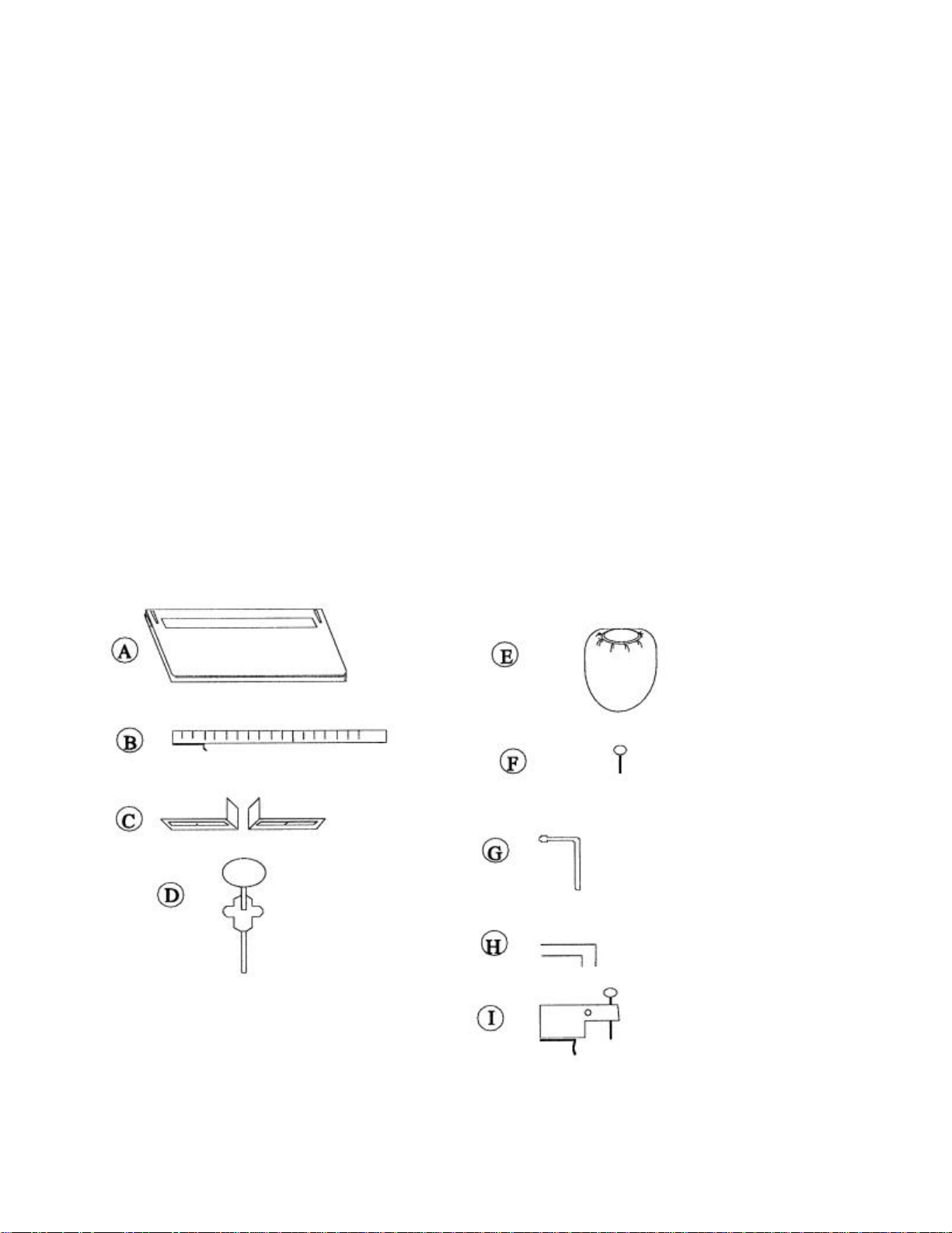
2. Remove and inspect the following items:
A. (1) Table Assembly (Illustration No.3)
B. (1) Back Gauge Angle and Scale (Illustration No. 1)
C. (2) Paper Side Stops (Illustration No. 3)
D. (1) Vertical Table Stop Assembly (Illustration No.4)
E. (l) Chip Bag
F. (4) Paper Side Stop Knob with Studs (Illustration No. 3)
G. (1) Chuck Release Key
H. (2) Hex Keys
I. (2) Stop Collar Set Screw
J. (1) Motor Warranty
K. (1) Back Gauge Clamp (Illustration No. 1)
L. (1) Operations Manual
Page 3
3
MODEL 200 BENCH MODEL DRILL
STARTUP PROCEDURES
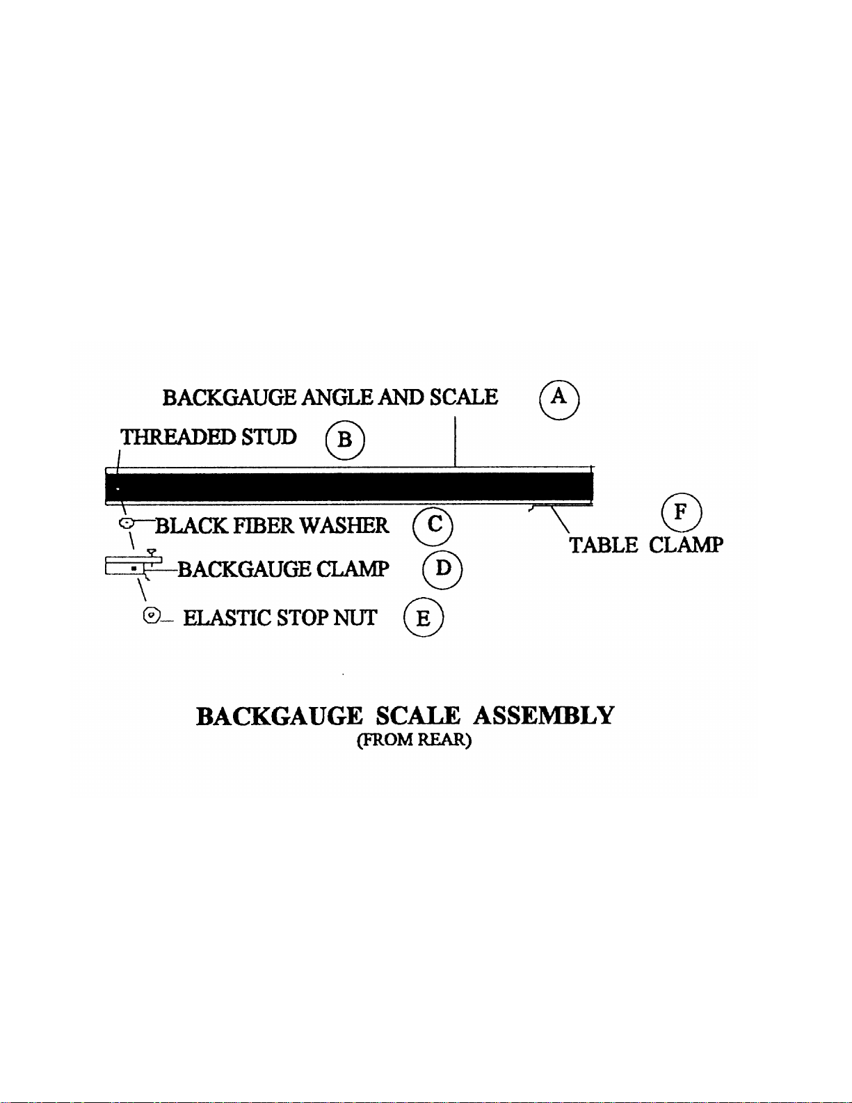
1. Refer to Back Gauge Scale Assembly (Illustration No. 1) and assemble back gauge assembly by
placing the black fiber washer (C) over the threaded stud (B). Place the back gauge clamp (D) on the
stud with the knob end toward the center of the assembly. Tighten the elastic stop nut (B) on the stud
until the nut is snug, allowing the clamp to move with only slight resistance.
ILLUSTRATION #1
Page 4

4
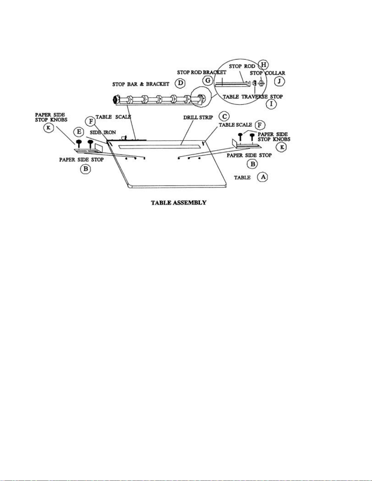
2. Using Illustration No.2, install the Table Assembly (Illustration No. 3) to the body of the
machine by sliding the table from left to right so as to place the metal table channel (H)
located on the bottom of the table assembly astraddle the four (4) traverse bearings (I)
located on the traverse rails (J) of the machine.
ILLUSTRATION #2
Loosen the setscrew in the end stop collar (J) (Illustration No. 3) on the stop bar and rotate the table
traverse stops (I), located on both ends of the stop bar, to the operating position. Using hand pressure,
squeeze the end stop collar and the next stop collar inside the stop collar rod bracket and retighten the
setscrew in the end stop collar. The stop bar should be unable to move in the bracket.
Page 5
5
ILLUSTRATION #3
3. Install the Back Gauge Scale Assembly (Illustration No. 1) on the Table Assembly (Illustra tion No.
3). Grasp the Back Gauge Assembly by holding both ends with the scale facing you. Tilt the
assembly and slide the Back Gauge Scale Assembly under the Pressure Foot Assembly (Illustration
No. 2-F). Both the table clamp and back gauge clamp extend outside of the table and contact the table
side irons (B) (Illustration No. 3). Adjust to the position desired using the table scales (F) embedded
in the rear corners of the table to aid alignment. “0” is the center of the hollow drill.
4. Install the Table Stop Assembly (Illustration No. 4) by inserting the stop rod (C) through the hole in
the top of the Shroud Assembly and attach the lock knob (E). Screw the stop rod through the lock
knob and into the threaded hole in the center top of the Upright Assembly (F). To adjust the table
height, loosen the lock knob (B), depress the handle until the correct table height is achieved
(explained later under Drill Bit Adjustments) and screw knob (B) into the Upright Assembly until the
stop rod meets resistance. Tighten the lock knob (E) against the Upright Assembly (F) to lock the
adjustment in place.
Page 6

6
ILLUSTRATION #4
5. As in Illustration No. 3, install the paper side stops (B) to the table by inserting two paper side stop
knobs through the slots of the paper side stops and screwing them into two of the three holes in the
table located in front of the drill strip (C). The location will depend on the size of the product being
drilled.
6. Attach the chip bag to the machine by stretching the mouth of the bag over the Chip Chute Assembly
(H) (Illustration No.4) and hooking it over the chip bag bracket (G).
7. Making sure nothing is interfering with the drill bit, plug the cord set into a grounded 1l0v outlet. To
turn the machine on, press the rectangular switch on the front of the shroud. When the machine is
operating, this switch will be lit.
Your Model 200 Paper Drill is now ready for use. With proper operation and maintenance, it will
give you trouble free operation for years.
Page 7

7
MODEL 200 BENCH MODEL DRILL
REMOVAL, INSTALLATION, AND ADJUSTMENT OF DRILL BITS
A. To remove a drill bit from the machine:
1. Remove the release hole guard from the chuck (C) (Illustration No.2) by lifting the small end of
the guard and unwinding from the chuck.
2. Insert the chuck release key in the hole in the chuck with the flat end downward and rotate the
handle until the drill bit is free.
B. To install a drill bit in the machine:
1. Grasp the drill bit and insert the large end into the chuck with upward pressure.
2. Place a non-metallic object (block of wood, etc.) und er the drill bit and secure it by depressing
the handle using adequate pressure to “seat” the drill bit.
3. Check the concentricity of the drill bit by momentarily turning on the machine. If the
concentricity is not satisfactory, remove the drill bit, rotate slightly and repeat the above steps.
C. To adjust the drill bit and table height:
1. Loosen the lock knob (B) (Illustration No. 4).
2. Depress the handle until maximum table height is achieved.
3. Turn the knob (B) until the desired table height is ac hieved. Counterclockwise rotation of the
knob will increase table height and decrease the distance between table and drill bit.
4. Once the desired table height is achieved, hold knob (B) and tighten the lock knob (B) against
the Upright Assembly to secure the adjustment.
NOTE: It is recommended that a piece of chipboard or similar material be placed on the table under the
material being drilled and the drill bit adjusted to drill partially through this material. This will
prevent scarring of the drill strip and dulling and flaring of the drill bit.
Page 8

8
TABLE SETUP AND DRILLING
Following are two methods for setting up the table to drill a particular hole pattern in the material.
The first is by the use of a template such as a piece from a previous job and the second is by
measurement.
ILLUSTRATION #5
METHOD NO. 1
1. Place a template of the material on the table such that the drill bit enters the hole furthest to the left
and the paper is centered on the table.
2. Adjust the paper side stops to trap and not allow lateral movement of the material on the table.
3. Loosen the knob of the back gauge scale and adjust the position of the back gauge scale to the correct
margin or back edge of the template.
Page 9

9
ILLUSTRATION #6
4. Using the hex key provided, loosen the setscrews in the stop collars on the stop bar. Loosen only the
stop collars interior of the stop bar bracket.
5. With the longest end of the pedestal pin taper to the left (Illustration No. 6) locate a stop collar tight
against the left side of the pedestal pin and tighten the setscrew.
6. Move the table laterally to the next hole, align the drill bit, repeat step 5, and repeat until all holes are
aligned.
7. To drill, li ft the pedestal pin and move the table to the original position, lower the pedestal pin
making sure it does not rotate, turn on the machine and depress the handle. To drill the next hole,
move the table to the left until the pedestal pin “clicks” over the next stop collar. Assert slight
pressure against the left side of the table to assure contact between the stop collar and pedestal pin.
Depress the handle, release and repeat this operation until all holes are drilled.
Page 10

10
METHOD NO. 2
1. Loosen the knob on the back gauge and set the margin you desire using the two scales embedded in
the rear corners of the table. Zero (“0”) on these scales indicates the center of the drill bit. Tighten the
back gauge scale knob to maintain its position.
2. Locate the product to be drilled against the back gauge scale. Center on the scale using the scale
graduations. Adjust the paper side stops to trap the material as in Method No. 1.
3. Move the table to align the “0” on the back gauge scale with the center of the drill bit.
4. With the pedestal pin in the same position as in Method No. 1, move a stop collar against the left side
of the pedestal pin and retighten the setscrew. The center of the material to be drilled has now been
established.
5. On the stop bar, move another stop collar to the distance required to equal the distance from the
center of the paper to the center of the first hole to be drilled. Make sure the measurement is from the
same sides of the stop collars. Other stop collar positions are determined and located in the same
manner.
6. The method of drilling is the same as in Method No. 1. Raise the pedestal pin and move the table to
the right. Lower the pedestal pin and move the table to the left until the pin “clicks” over the first
stop collar. With a gentle pressure against the left side of the table, depress the handle and release
slowly to drill the hole. Move the table until it “clicks” over the next stop collar and repeat until all
holes are drilled.
Page 11

11
ILLUSTRATION #7
FOR STATIONARY TABLE DRILLING
1. Remove the setscrews from two adjacent stop collars and replace them with the longer setscrews that
come with the accessories.
2. Move the table to the desired position.
3. Tighten the longer setscrews in the stop collars so that a setscrew rests against both sides of the
pedestal preventing movement of the table.
Page 12

12
MODEL 200 BENCH MODEL DRILL
MAINTENANCE SCHEDULE
LUBRICATION AND INSPECTION
1. Every two weeks:
a. Remove the table by lo osening the left end collar on stop bar assembly and rotating the table travel
stop down to clear the pedestal. Pull the table to the right until the table clears roller bearings.
Inspect the four traverse bearings for build-up on the outer race and lubricate the inner race with a
drop of light machine oil. Rotate the bearings to check for free rotation.
Replace the table in the same manner as removed and check the table traverse for free travel.
b. Stop pin - Lubricate the stop pin with light machine oil, working the pin up and down and rotating
a few times for proper lubricant distribution.
2. Every 30 days:
a. Pivot Assembly - Remove the back panel and work the handle up and down to determine all pivot
points in back portion of machine. Lubricate these points with light machine oil.
3. Every 12 months:
Remove back panel and lubricate the lift pin with a good grade of light oil.
CAUTION: KEEP FINGERS FROM BETWEEN LIFT COMPONENTS.
NOTE: Refer to your Trouble Shooting Guide for problem solving.
OBSERVE ALL SAFETY PRECAUTIONS DURING PREVENTATIVE MAINTENANCE
OF THIS MACHINE MODEL 200 BENCH MODEL DRILL
Page 13

13
TROUBLE SHOOTING GUIDE
PROBLEM: Drill bit not concentric.
CAUSE Foreign material in chuck or on drill-plug.
CORRECTION: Inspect and clean.
CAUSE: Drill bit bent.
CORRECTION: Replace.
CAUSE: Drill bit not inserted and/ or in chuck properly. Reinsert drill bit
CORRECTIONS: Correctly.
CAUSE: Chuck not tight to spindle.
CORRECTION: Tighten set screw.
PROBLEM: Drill bit not drilling.
CAUSE: Drill bit plugged.
CORRECTION: Remove and clear chips. Check for other foreign matter.
CAUSE: Drill bit dull.
CORRECTION: Sharpen. (Follow factory cutting angle.)
NOTE: In extreme conditions, drill chuck and/or chip chute may be plugged. Remove
drill, loosen chip chute, pull down, and clean. See Operation Manual.
PROBLEM: Traverse table drags or skips during operation.
CAUSE: Roller bearings dry or damaged.
CORRECTION: Remove table, lubricate.
CAUSE: Table guides out of adjustment.
CORRECTION: Adjust.
CAUSE: Table damaged.
CORRECTION: Check table for damage. Repair or replace.
NOTE: In order to maintain a smooth table operation, DO NOT sit on, lean on, or
force table out of alignment.
Page 14

1
4
ILLUSTRATION #6
A. Vertical Stop Knob
B. Shroud Assembly
C. Vertical Stop Lock Knob
D. Motor
E. Handle Assembly
F. Pivot Arm Set Assembly
0. Draw Bars
H. Chip Chute Assembly
I. Lift Pin
J. Ball Bushing
K. Fork Assembly
L. Upright Assembly
M. Base
N. Wood Grip
0. Pivot Hub
P. Pressure Foot Assembly
Q. Stop Collar Assembly
 Loading...