

MBM 1800S Service Manual

Sales • Service • Repair
Professional Service – Fast Nationwide Shipping
1-866-455-9900
www.OnlineSkyline.com
CustomerService@onlineskyline.com
SERVICE MANUAL
MBM Air Suction Folder
Model 1800S
MBM Corporation
Ver. 03 160939 NW

2
CONTENTS
1. Safety Instructions …………………………….……………………... 4
2. Caution during Maintenance Service ………………………………. 7
3. P
arts Names ………………………………………………………….. 8
4. Designation and Functions of Operati
on Panel ……………..……. 10
5. Operations …………………………………………...……………… 1
1
6. St
ructure of the sections
6-1 Layout Drawing of Overall Machine ............................................................. 12
6-2 Covers ............................................................................................................. 13
6-3 Layout of Motor and Solenoid ....................................................................... 14
6-4 Layout of Sensors, Switch (SW) and Solenoids ............................................ 15
6-5 Wiring Diagram .............................................................................................. 16
6-6 Suction Section ............................................................................................... 17
6-7 Paper Height Detection Section ..................................................................... 17
6-8 Drive Section .................................................................................................. 18
6-9 Separating Air Section .................................................................................... 18
6-10 Paper Transport Section .................................................................................. 19
6-11 Paper Feed Table ............................................................................................ 19
6-12 Control Section ............................................................................................... 20
6-13 Option ............................................................................................................. 20
7. Skew Adjustment ………………………………………..…………...21
8. Dis
assembling Suction Belt Assembly (Exchanging Suction Belt)...23
9. E
xchanging Clutch Unit……………………………...………………27
10. E
xchanging Solenoid Unit ……………………...…………………..28
11
. Replacing Separator
Rubber …………...………………………… 28
12. Repl
acing Timing Belt …………………………………………….. 29

3
13. Replacing Interceptor ……………………………………….......... 31
14. Rem
oving Paper Guide at Transport Section (Replacing
Feed Sensor and/or Ultrasonic Double Feed Sensor) ………...…. 31
15. Rem
oving Paper Feed Table (Replacing Paper
Empty
Sensor and/or Paper Sensor for inch size paper) ………...………32
16. Replacin
g Other Sensors (
Paper Floating Height Sensor, Top Cover
Switch, Paper Ejection Sensor and Others
) …………...…………….… 33
17. Repl
acing Paper Ejection Belt and Replacing Ejection Roller
Home Position Switch ………………………...………………..…. 34
18. Zer
o Setting of Folding Tables 1 and 2 ………….. ……………… 35
19. T
est Mode ………………………………………………...………... 36
20. Check Lamps, Err
or Codes and Troubles ……………………….. 37
21. T
roubleshooting ……………………………………………...……. 39
22. E
rror Codes …………………………………………….
………….. 42
23. Other
Troubleshooting and Cleaning ……………...………………43
24. Other
Adjustable Functions (Weight Arm an
d
T
able 2 Base Plate) ………………………………………………… 44

4
1. Safety Instructions
Definition of Symbols and Notes
The following names and signs stand for possible dangers.
Danger
This symbol stands for immediate danger. Disregarding these instructions may cause severe injury.
Caution
This symbol stands for a potentially dangerous situation. Disregarding these instructions may lead to
injuries or damage to property.
Danger
Make sure that the machine is electrically grounded to prevent electrical shock.
Operate the machinery within reasonable voltage range. There is a risk of electrical shock or fire if a higher or
lower voltage is used, or if an electric current is utilized with a frequency not within the range stated above.
Do not place any object on top of this machine. There is a risk of electrical shock or fire if water or any
foreign object enters the machine.
Handle the power cord with care. There is a risk of electrical shock or fire if the cord is damaged, broken,
or placed under a heavy object.
Do not insert or remove the power plug when water is present.
Do not remove the cover of this machine. There is a risk of an electrical shock.
Do not reconfigure the electronics of this machine. There is a risk of an electrical shock or fire.
Do not operate the machine if it is emitting smoke or a strange odor. Turn off the machine, unplug it from
the outlet and contact your dealer.
Do not operate the machine if the power cord is generating heat or emits a strange smell. Turn off the
machine, unplug it from the outlet and contact your dealer.
If a foreign object enters into the machine, turn off the power switch and unplug the power plug, then
consult your dealer.
In the event of a thunderstorm, unplug the machine.
Caution
Keep hair, clothing, and jewelry away from the machine while operating. Serious injury may result.
Do not put the machine on an unstable or slanted surface. Doing so may cause the machine to drop or fall
over, causing damage and possible injury.
Store and operate the machine in a clean, dust-free environment with low humidity. Avoid areas with high
moisture, extreme temperatures and excessive dust, as these conditions may cause machine failure or
electrical shock.
Operate the machine at the temperature of 5 degrees to 35 degrees C.
Be sure to grasp the power cord by the plug when unplugging it from the electrical outlet. Not doing so may
cause damage to the cord and possible electrical shock or fire.
Be sure to pull the power plug out of the electric outlet before moving the machine. Not doing so may cause
damage to the cord and possible electrical shock or fire.
Unplug the power plug from the electrical outlet when this machine is not in use.
The socket-outlet shall be installed near the equipment and shall be easily accessible.
5
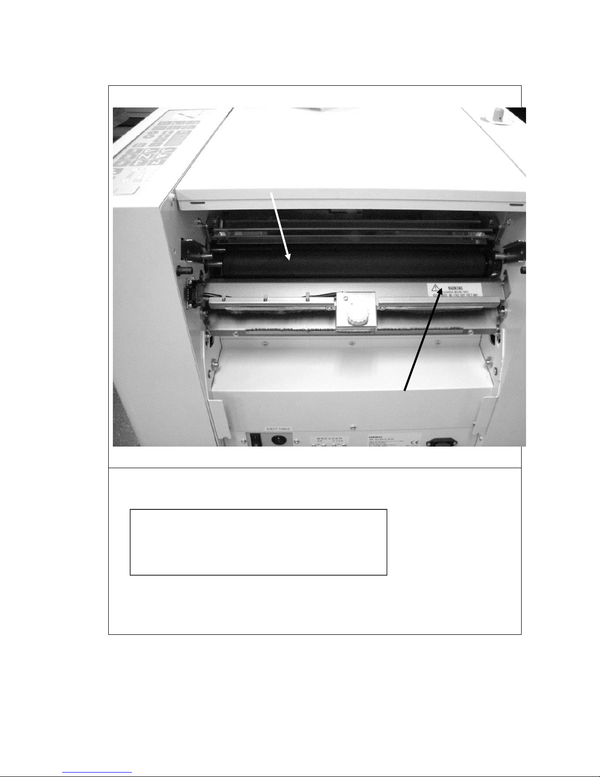
WARNING 1
①:Moving Parts
②:Warning Label
WARNING
HAZARDOUS MOVING PARTS
KEEP FINGERS AND OTHER BODY PARTS AWAY.
①
②
6
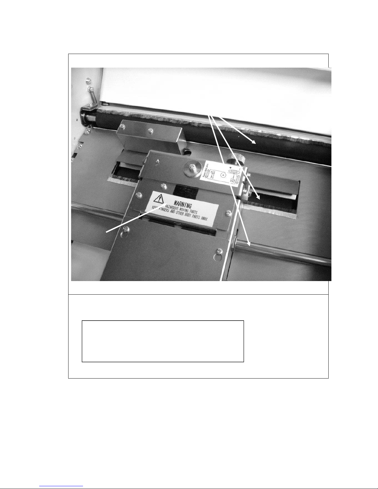
WARNING 2
①:Moving Parts
②:Warning Label
WARNING
HAZARDOUS MOVING PARTS
KEEP FINGERS AND OTHER BODY PARTS AWAY.
②
①

7
2. Caution during Maintenance Service
Turn off the machine and unplug the power plug to avoid electrical shock.
(1) Hold the connector to avoid damaging cables when plugging or unplugging the connector.
(2) When wiring, pay attention on over-tension or over-slack of wire harness to avoid touching to
movable or rotary part.
(3) Clean the photo sensor to avoid the machine error.
(4) Clean the belts, rollers and other related area to avoid paper feed error.
(5) When cleaning, use a towel after wringing out water.
(6) Do not use an organic solvent to avoid machine trouble.
(7) After cleaning, operate the machine only in the status that machine is not dry.
8
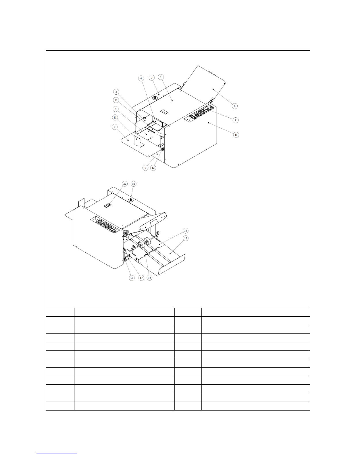
3. Part Names
Name Number Name
① Top cover ⑫ Skew Adjustment Knob
② Left side cover ⑬ Paper Ejection Table
③ Paper Guide(Left & Right ) ⑭ Paper Ejection Roller
④ Paper Height Detection Sensor ⑮ Auxiliary Paper Ejection Table
⑤ Auxiliary Feed Table ⑯ Power Switch
⑥ Table 1 ⑰ Paper Ejection Table Socket
⑦ Operation Panel ⑱ Air Adjustment Knob
⑧ Paper Feed Table ⑲ Weight Arm
⑨ Door for Table 2 ⑳ Top cover Knob
⑩ Right side cover
Table 2
⑪ L Stopper guide
Table 2 is set under the Paper Feed Table in the machine, which you find when opening the door ⑨ for the table 2.

9
Upper Cover is open to adjust
belt feeder assembly.
Belt Feeder Assy
Paper Floating Height Adjuster
Suction Air Adjuster
Error Code Chart
Feed Angle Adjustment Dial
10
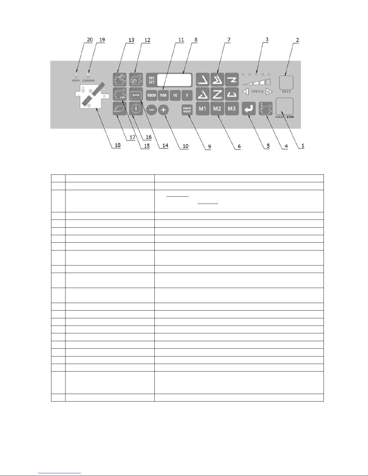
4. Designation and Functions of Operations Panel
No.
Designation/Indication Function
①
STAR T/STOP key
Starts and stops machine.
②
TEST key
1)Test folds two sheets without counting.
2) Also used fo r test bl ow wit hout fol ding (presse d more th an 2
seconds until buzzer sounds.)
③
Speed adjustment key Select 5 speed.
④
Paper feed table up/down key Moves up and down the Paper Feed Table
⑤
Store key Memorize fold position after adjustment is done.
⑥
Memory 1/2/3 key
Memorize three special fold types.
⑦
Fold type key Select 6 fold types and store job routine.
⑧
Counter
Shows the number of sheets, position of the stopper of Table 1 and 2,
and paper size.
⑨
Clear/Reset key
Clears the counter / resets after an error.
⑩
+/- key
Use for adjusting position of the stopper of Table 1 and 2, the position
of paper ejection roller, and inputting paper length
⑪
Numerical key
Use for inputting the number of sheets to be folded, length of nonstandard size paper, factors of interval function and others.
⑫
Table 2 stopper move mode key Use to adjust Table 2 Stopper position.
⑬
Table 1 stopper move mode key Use to adjust Table 1 Stopper position.
⑭
Paper length input mode key Use to input paper length for non standard norm paper.
⑮
Paper ejection roller move key Use to adjust position of Paper Ejection Roller.
⑯
Interval key Sets time and number of interval function during folding work.
⑰
Double Feed Error Detection key Sets double feed error detection ON/OFF.
⑱
Trouble Locating Map
①②③④
⑤ Indicates location of trouble.
In case
of Double Feed ①④⑤ lamps flash at the same time. Display indicates E-13.
⑲
Cleaning lamp
Indicates when cleaning of the FEED section (belt, roller) is necessary.
It lights every 10,000 sheets of folding.
Can disable this function. Refer detailed section.
⑳
Perforation mode lamp Indicates when the optional perforating unit is installed.

11
5. Operations
1) Turn power switch on.
2) Set papers
3) Folding T est
3-1) Press one of the fold type keys to test.*
3-2) Set speed.
3-3) Press the TEST key.
3-4) Stoppers of Table 1 and Table 2 moves to home position once.
Then, stoppers of the Tables move to appropriate folding positions.
3-5) After folding two pieces of papers, machine stops. Examine 2nd folded paper.
*: If fold type key is not pushed, machine operates based on previously set folding pattern and
speed.
4) Fold by Adding Counter
4-1) Clear the numbers of counter and set it to zero.
4-2) Press START key.
4-3) Folding continues until out of paper in the Feed Table.
5) Fold by Subtracting Counter
5-1) Set desired number of fold.
5-2) Press START key.
5-3) The folding stops at the time when reached to the setting numbers.
6) The machine can be stopped anytime by pressing STOP key or when error occurred.
Refer operation manual for details.
12
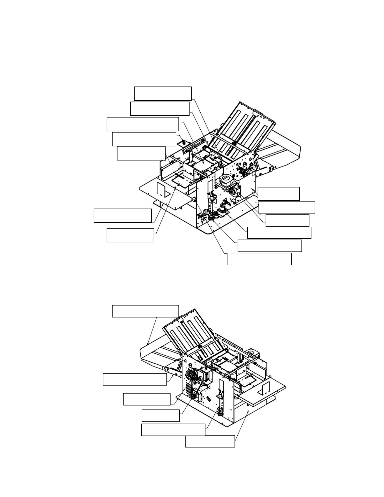
6. Structure of the sections
1) Layout Drawing of Overall Machine
Suction Belt Feeder Assy.
Air Adjustment Knob
Paper Guide
Double Feed Sensor
Feed Angle Adj. Dial
Table Up/Down Drive
Skew Adjustment Knob
Paper Feed Table
Auxiliary Feed Table
Control PCB
Separation Blower
Suction Blower
Drive Section
Paper Ejection Table
Aux. Paper Ejection Table
Door for Table 2
Table Up/Down Screw
Main Moto
r
13
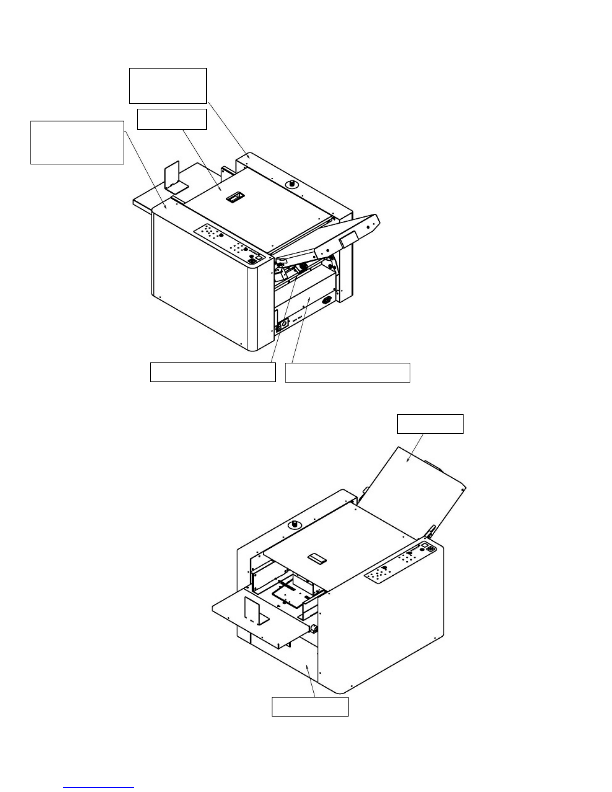
2) Covers
Paper Ejection Lower Cove
r
Left Side Cover
Door for Table 2
Table 1 Cover
Top Cover
Right Side Cover
(Front Cover)
Paper Ejection Upper Cover

14
3) Layout of Motor and Solenoid
Separation Blowe
r
Table Up/Down Moto
r
Suction Section Solenoi
d
Suction Blower
Paper Ejection Belt Driving Motor
Paper Ejection Roller Positioning Moto
r
Table 1 Drive Motor
Main Motor
Table 2 Drive Motor
 Loading...