

MBL 6010 D Owner's Manual
mbl 6010 D
1
Important Information!
Attention! Keep the preamplifi er away from high humidity, vibration, excessive
dust and direct sunlight. Excessive heat or cold will a ect the preamplifi er´s
functionality. The permitted operating temperature is 10°C up to 40 °C (50°F
up to 104°F). Avoid extreme variations in temperature. Do not operate the pre-
amplifi er near other electric appliances (for instance neon light and motors).
The preamplifi er should not be opened without the assistance of a qualifi ed
technician!
WARNING: Do not connect any musical instruments (e.g. electric guitar etc.) to
the pre-amplifi er. This use for a purpose for which it is not designed – i.e. for a
purpose other than playback - can result in irreparable damage to the equip-
ment.
Do not operate the device under condensation! Allow the preamplifi er to warm
up at least three hours to room temperature after it has been exposed to low
temperatures.
Make sure that no fl uid-fi lled vessels (glasses,vases…) are put on the device to
prevent water from ingressing the device, and the device is never exposed to
splash water.
Please discard used batteries in accordance to your country´s laws.
KETI, CE-Marking
This product conforms to the requirements of the EMC directive and low-volt-
age directive. Your MBL component complies with the household power and
safety requirements in your area.
Warranty
Please pay attention to the details given in the warranty card which accompa-
nies the unit. Warranty is only issued, if you send back the warranty card.

mbl 6010 D
2
Page
3 Scope of Delivery
4 mbl 6010 D Views
4 mbl 6010 D Front view
5 mbl 6010 D Rear view
6 1. Installation
6 1.1 General Precautions
6 1.2 Connection to the outlet
7 2. Connecting Other Components
7 2.1 Outputs
7 2.2 Inputs
8 3. Front Panel Controls
8 3.1 Input Selector
9 3.2 Input Section
10 3.3 Volume Control
10 3.4 Digital Volume Display
10 4. Processor / Bypass
10 5. Output Groups
11 5.1 Output on /o switches
11 5.2 Output Level Unit
11 6. Remote control
12 7. Options (modules)
12 7.1 Balanced-In
12 7.2 Phono
13 8. Maintenance
14 9. mbl 6010 D Construction
14 9.1 mbl 6010 D - Base Unit
14 9.2 mbl 6010 D - Options
15 10. Troubleshooting
17 Specifi cations
mbl 6010 D
3
Scope of Delivery
mbl 6010 D Preamplifi er
A/C Power Cord
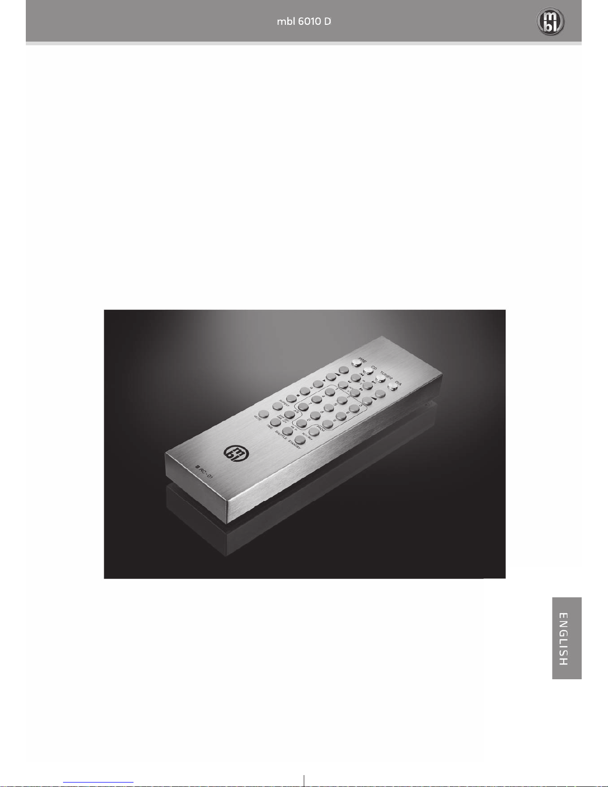
mbl System Remote Control SFBG3
(batteries included)
mbl System Remote Control SFBG3
mbl 6010 D
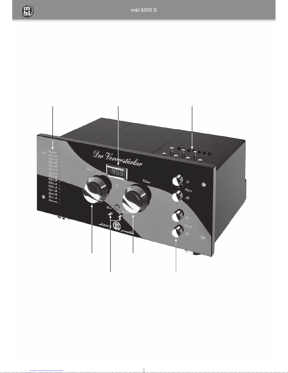
4
indicator LEDs display
input selector
input level unit
with record selector
volume control
output selector switches output level unit
mbl 6010 D
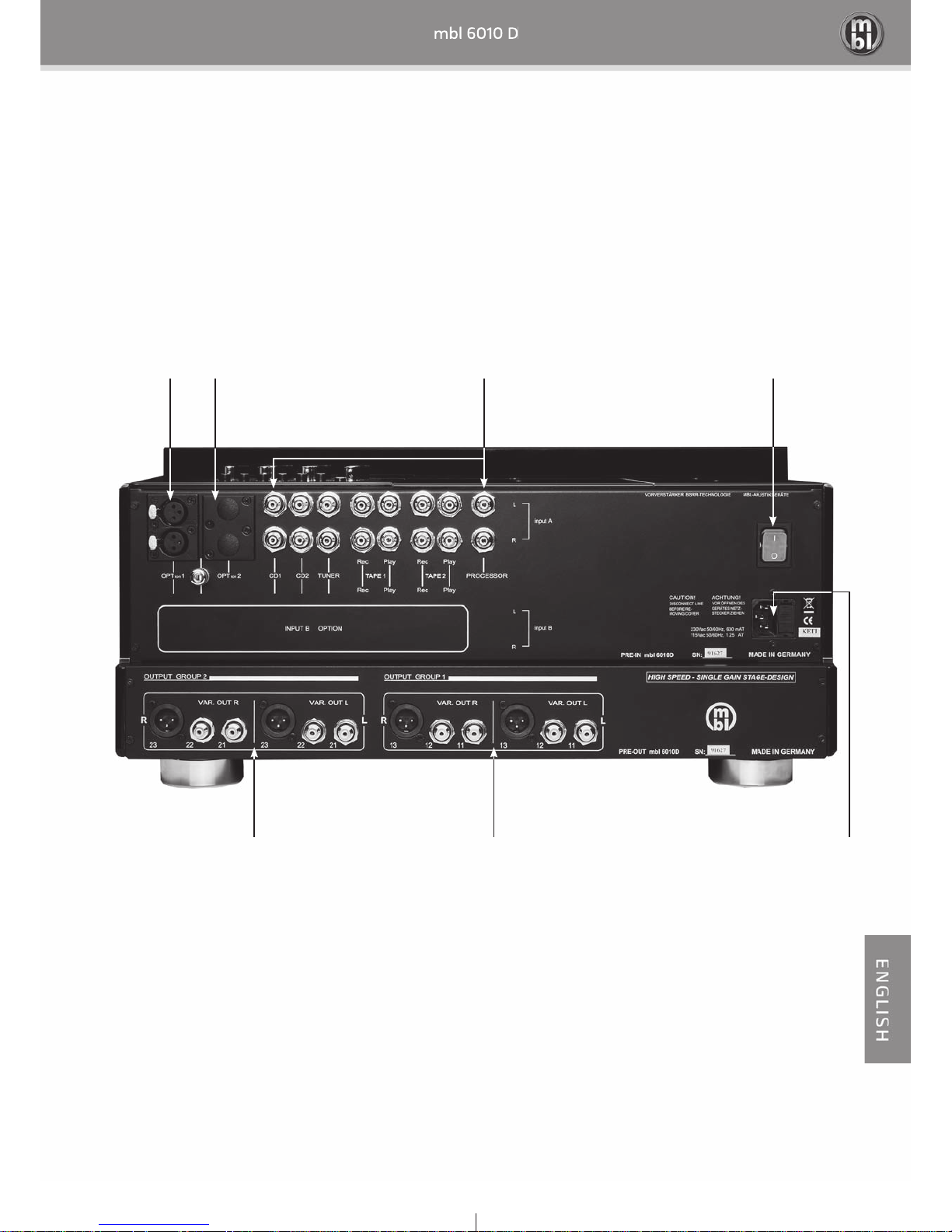
5
balanced-in optional input RCA inputs power switch
variable output group 2 variable output group 1 connector for power cord
and fuse holder

mbl 6010 D
6
1. Installation
1.1 General Precautions
Keep your preamplifi er away from humid places. For example, do not operate the device near air dampeners or in
bathrooms. The relative humidity may be between 10% up to 90% in operation, as long as condensation does not
occur. As with any other electrical device, direct contact with water will not only damage the preamplifi er but will
lead to a hazardous situation that will result in death or serious injury!
Excessive heat or cold will a ect the unit’s functionality. Therefore, do not operate the unit near a heat source
such as a radiator and do not expose it to direct sunlight. The permitted operating temperature is 10°C up to 40 °C
(50°F up to 104°F), the storage temperature is between -10°C and 50°C (14°F and 122°F).
Condensation may emerge inside the device, if temperature changes excessively within a short time. In this case,
do not connect the device to the mains as this may result in a short-circuit, leading to malfunctions or damage.
If you, for example, transfer the unit from outside into a heated room in winter, wait at least three hours before
connecting and operating it. Store the device only in a place where the temperature and humidity are constant
as frequent condensation will harm the device. The environment should be free from dust or sources of electric
interference such as fl uorescent tubes or engines.
Do not expose the device to heavy vibrations as this may lead to malfunctions or damages. Install the device in a
level and stable place. Please consider the heavy weight of MBL products!
1.2 Connection to the Outlet
Your preamplifi er features two high-quality toroidal transformers for power supply. Depending on the setting, it
is proposed for the connection to the outlet providing either 230 V/50 Hz or 115 V/50/60 Hz. The device is shipped
with the voltage setting appropriate for the country where it is sold.
If you want to operate the device in a country with a di erent mains voltage, please contact a qualifi ed technician
to have the operating voltage altered accordingly. For safety reasons, this can be achieved only after opening the
enclosure of the device. Further, the fuse must be replaced: A 0.63 amps sb fuse is required for an operating volt-
age of 230 V, a 1.25 amps sb fuse for 115 V.
Note: If you connect your preamplifi er to the outlet with an inadequate voltage setting, it will result in heavy dam-
age. MBL assumes no responsibility for accidents and damages caused by improper settings. Further, changes
made to the voltage setting by a technician will not be covered by the warranty either.
Caution! Whoever opens an electric device without previously disconnecting it from the outlet puts his life at risk
carelessly and irresponsibly. Unplug the unit before opening!
mbl 6010 D
7
2. Connecting Other Components
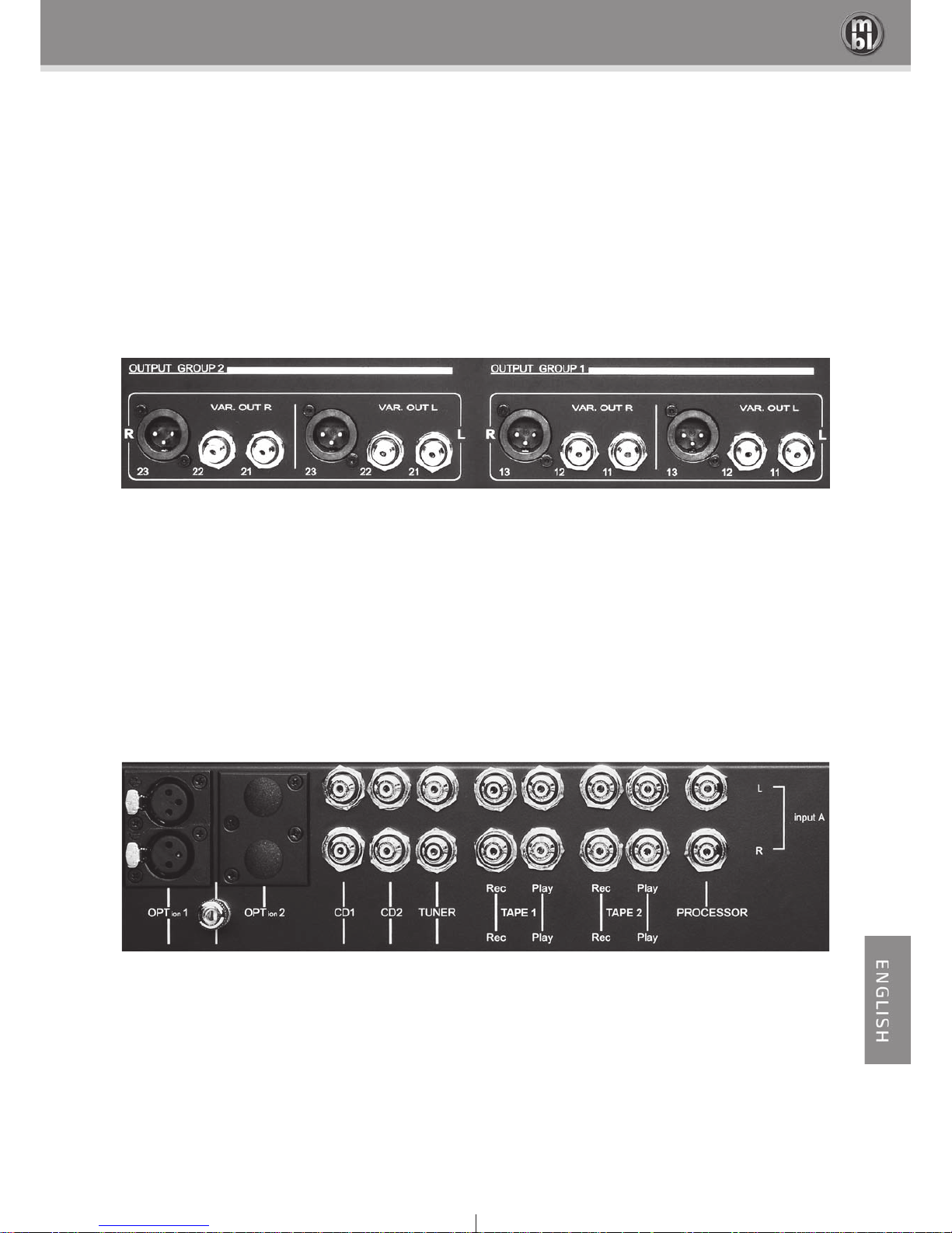
2.1 Outputs
The mbl 6010 D is designed for connecting one or more power amplifi ers. It provides the following analog outputs
for power amplifi er connection:
OUTPUT GROUP 2 OUTPUT GROUP 1
2 x RCA outputs (21 and 22) per channel 2 x RCA outputs (11 and 12) per channel
1 x balanced XLR output (23) per channel 1 x balanced XLR output (13) per channel
2.2 Inputs
Up to 7 source devices can be connected to your mbl 6010 D. For this purpose, it provides the following analog
inputs:
OPTION 1 | OPTION 2 CD 1 | CD 2 | TUNER TAPE 1 TAPE 2 PROCESSOR
The inputs OPT 1 and OPT 2 are optional inputs reserved for additional modules such as Phono MC or balanced
input. OPT 1 is already equipped with a balanced input.
mbl 6010 D
8
3. Front Panel Controls
3.1 Input Selector
With the input selector switch you can select one of the various sources connected to the preamplifi er. The pro-
cessor enables the connection of an extern surround-decoder. Choosing this input will engage a signal to the con-
nected amplifi er (Bypass). This gives the possibility to switch between audio (music replay) and video (DVD). Use
buttons Opt 1A / Opt 1B / Opt 2 and to select plugged in Phono MC or Balanced-In modules.
Input selector settings:
Input Input selector Input section* Function
TUNER
Tuner A
tuner input
TAPE 1
Tape 1 A
tape machine at TAPE 1 input
TAPE 2
Tape 2 A
tape machine at TAPE 2 input
CD 1
CD 1 A
CD player at CD 1 input
CD 2
CD 2 A
CD player at CD 2 input
OPT 1
Opt 1 A
Phono MC or Balanced-In module at OPT 1 input
OPT 2
Opt 2 A
Phono MC or Balanced-In module at OPT 1 input
PROCESSOR
Processor A
bypassing the signal of an external surround processor
* Input section B is an optional expansion.
mbl 6010 D
9
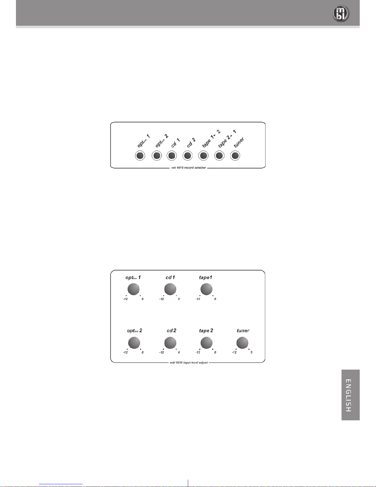
3.2 Input Section
The input section is composed of level encoders and record buttons.
Record selector
With the record select buttons the signal source for a connected tape machine can be controlled. The recording
procedure can be performed independently of playback; for example, the tuner can be routed to the output using
the input control while a tape recording is being performed from CD. The recording quality can be checked im-
mediately during the recording process; for this purpose, set the Input control to Tape 1 or Tape 2. (Tape 1 refers
to the machine connected to the TAPE 1 connector and Tape 2 to the device connected to the TAPE 2 connector).
Input level unit
The precision potentiometers are associated with the respective inputs and provide input-signal attenuation by up
to 12 dB in order to prevent volume peaks when changing between sources.

mbl 6010 D
10
3.3. Volume Control
The volume control is a “MSP” special metal potentiometer with a channel alignment of better than 0.8 dB. This
MSP is shielded against magnetic and electrostatic fi elds. Rotating the Volume control clockwise will increase the
volume, rotating it counter clockwise will lower the volume.
3.4 Digital Volume Display
The digital display indicates the total-volume rotary angle as a percentage. The rotary angle is set by a separate
potentiometer and is then displayed. The displayed values provide a volume reproduction of: 00.0…100.0%.
Note: It is possible that the last digit jumps between two numbers. This is not a malfunction, it proves that here is
a high grade analog potentiometer build in and not a digital component.
4. Processor / Bypass
To the processor / bypass input you can connect an external surround decoder to the power amplifi er. When you
select this input, any signal presented here will be switched to the output directly (bypass function). This allows an
easy switching between audio (music replay) and video (DVD, etc.).
Note: Volume can not be controled by the preamplifi er.
Attention! BYPASS/Processor: never use this input for unregulated high level signals (e.g. CD player). High levels
may cause defects on connected amplifi ers and speakers.
5. Output Groups
The output stage is subdivided into two groups for connecting multiple power amplifi ers. Each group features two
balanced XLR connectors and four RCA connectors.
mbl 6010 D
11
6. Remote Control
Using the remote control will overwrite the unit´s adjustment. The LED “Remote” indicates that the settings of the
switches (Input selector and Out1 and Out2) do not correspond to the current status of the amplifi er.
However the LEDs indicate the correct status of the unit.
Controlling the unit without remote control will reset the device to the adjustment former made directly on the
unit.
If the position of the switches conforms to the unit´s current status, the “Remote” LED does not light.
Adjustment referring to the volume control is not a ected.
Note: The amplifi er saves the adjustment, even if you turn it o . For saving adjustment the amplifi er needs at least
2 seconds before you turn it o .
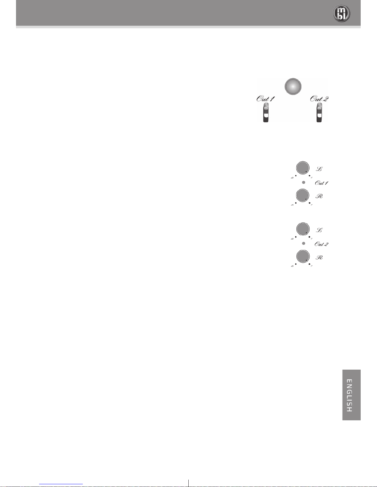
5.1 Output on/o Switches
Out 1 and Out 2 are used for switching on and o GROUP 1 and/or GROUP 2
output sections. Sliding a switch upward the respective outputs are on, sliding it
downward they are o . The LED between output level potentiometer indicates
the selected status. If the LED light is lit, the outputs are on, otherwise they are
o . With the Remote control you can also switch the outputs on / o .
5.2 Output Level Unit
The output level unit allows precise adaptation of the stereo-signal balance to
the environmental acoustics. Discrete attenuation by up to 12 dB is provided for
each channel of the output modules.

mbl 6010 D
12
7. Options (modules)
All installations must be performed exclusively by your MBL dealer.
7.1 Balanced-In
The Balanced-In module contains an active balancing stage for connecting a balanced signal to the preamplifi er
inputs.
Balanced:
2 = + In Phase
3 = - Out of Phase
1 = Ground, 0 V
7.2 Phono
An absolute must for the analog record enthusiast - the Phono-MC-Module. The Phono-MC-Module features a
separate RIAA equalizer for optimum adjustment and the RIAA poles are distributed to multiple amplifi ers, thus
increasing the amplifi cation headroom of each amplifi er and reducing distortion to almost zero. At a gain reserve
of 12 dB it still results in an incredible overload resistance of 24 dB! The deviation from the RIAA curve is less than
0.2 dB.
The Phono-MC-Module can optionally be installed at one of the provided spaces of the Input group A.
 Loading...